EP1130672A2 - Indicateur de charge de pile - Google Patents
Indicateur de charge de pile Download PDFInfo
- Publication number
- EP1130672A2 EP1130672A2 EP01104860A EP01104860A EP1130672A2 EP 1130672 A2 EP1130672 A2 EP 1130672A2 EP 01104860 A EP01104860 A EP 01104860A EP 01104860 A EP01104860 A EP 01104860A EP 1130672 A2 EP1130672 A2 EP 1130672A2
- Authority
- EP
- European Patent Office
- Prior art keywords
- battery
- state
- cell
- sensing
- voltage
- Prior art date
- Legal status (The legal status is an assumption and is not a legal conclusion. Google has not performed a legal analysis and makes no representation as to the accuracy of the status listed.)
- Withdrawn
Links
Images


Classifications
-
- H—ELECTRICITY
- H01—ELECTRIC ELEMENTS
- H01M—PROCESSES OR MEANS, e.g. BATTERIES, FOR THE DIRECT CONVERSION OF CHEMICAL ENERGY INTO ELECTRICAL ENERGY
- H01M10/00—Secondary cells; Manufacture thereof
- H01M10/42—Methods or arrangements for servicing or maintenance of secondary cells or secondary half-cells
- H01M10/48—Accumulators combined with arrangements for measuring, testing or indicating the condition of cells, e.g. the level or density of the electrolyte
- H01M10/488—Cells or batteries combined with indicating means for external visualization of the condition, e.g. by change of colour or of light density
-
- H—ELECTRICITY
- H01—ELECTRIC ELEMENTS
- H01M—PROCESSES OR MEANS, e.g. BATTERIES, FOR THE DIRECT CONVERSION OF CHEMICAL ENERGY INTO ELECTRICAL ENERGY
- H01M10/00—Secondary cells; Manufacture thereof
- H01M10/05—Accumulators with non-aqueous electrolyte
- H01M10/052—Li-accumulators
- H01M10/0525—Rocking-chair batteries, i.e. batteries with lithium insertion or intercalation in both electrodes; Lithium-ion batteries
-
- Y—GENERAL TAGGING OF NEW TECHNOLOGICAL DEVELOPMENTS; GENERAL TAGGING OF CROSS-SECTIONAL TECHNOLOGIES SPANNING OVER SEVERAL SECTIONS OF THE IPC; TECHNICAL SUBJECTS COVERED BY FORMER USPC CROSS-REFERENCE ART COLLECTIONS [XRACs] AND DIGESTS
- Y02—TECHNOLOGIES OR APPLICATIONS FOR MITIGATION OR ADAPTATION AGAINST CLIMATE CHANGE
- Y02E—REDUCTION OF GREENHOUSE GAS [GHG] EMISSIONS, RELATED TO ENERGY GENERATION, TRANSMISSION OR DISTRIBUTION
- Y02E60/00—Enabling technologies; Technologies with a potential or indirect contribution to GHG emissions mitigation
- Y02E60/10—Energy storage using batteries
Definitions
- the present invention relates to an apparatus for sensing a state of a battery such as charge and/or discharge state of the battery such as a lithium ion secondary battery.
- the battery in an excessive charge/discharge state of the battery e.g., the lithium ion secondary battery causes a deterioration of the battery so that a battery performance cannot be secured.
- a conventional cell controller requires a wide installation area with a large circuitry even if circuit parts are installed on electrodes of cell after the cell is manufactured.
- a complicated wiring is needed to connect each cell to the cell controller and each cell has a mutually different potential. Hence, its circuit complexity is increased. In addition, it is difficult to install the circuit on laminated electrodes of such a bipolar cell or so forth.
- the conventional cell controller consumes relatively largely a current in a sensing operation of, for example, discharge quantity.
- an object of the present invention to provide an apparatus for sensing a state of a battery in which a voltage-responsive optical sensing device such as a light emitting device, luminascent semiconductor micro-crystals and/or liquid crystal device to sense an excessive charge/discharge state of the battery can integrally and simply be installed into an inside of the battery without unnecessary wiring and the performance of battery can sufficiently be secured with less consumption of current.
- a voltage-responsive optical sensing device such as a light emitting device, luminascent semiconductor micro-crystals and/or liquid crystal device to sense an excessive charge/discharge state of the battery
- an apparatus for sensing a state of a battery comprising: a voltage-responsive optical sensing device having an optical characteristic that changes in response to a variation in a voltage across positive and negative electrodes of a cell constituting the battery; and a state sensing system that senses a change in the optical characteristic of the voltage-responsive optical sensing device to sense the state of the battery.
- Fig. 1 is a schematic cross sectional view of a cell of a lithium ion secondary battery to which a battery state sensing apparatus in a first preferred embodiment according to the present invention is applicable.
- Fig. 2 is a schematic cross sectional view of a cell of a lithium ion secondary battery to which a battery state sensing apparatus in a second preferred embodiment according to the present invention is applicable.
- Fig. 3 is a schematic cross sectional view of a cell of a lithium ion secondary battery to which a battery state sensing apparatus in a third preferred embodiment according to the present invention is applicable.
- Figs. 4A and 4B are schematic cross sectional view and perspective view of a laminated multi-cell secondary battery to which the battery state sensing apparatus in a fourth preferred embodiment according to the present invention is applicable.
- Figs. 5A, 5B, 6A, and 6B are explanatory views of the battery state sensing apparatus in a fifth preferred embodiment for explaining an operation of the battery state sensing apparatus of the fifth preferred embodiment.
- Fig. 7 is a characteristic graph representing a discharge curve of the cell to which the battery state sensing apparatus according to the present invention is applicable.
- Fig. 8 is an explanatory connection diagram of a cell group of the cells connected in series with each other to which the battery state sensing apparatus in a sixth preferred embodiment according to the present invention is applicable.
- Fig. 9A is an explanatory connection diagram of the cell group of the cells connected in series with each other to which the battery state sensing apparatus in a seventh preferred embodiment according to the present invention is applicable.
- Fig. 9B is an explanatory connection diagram of the cell group of the cells connected in parallel to each other to which an alternative of the battery state sensing apparatus in the seventh preferred embodiment shown in Figs. 9A and 10 is applicable.
- Fig. 10 is an explanatory cross sectional view of the cell of the cell group to which same components of the battery state sensing apparatus shown in Fig. 9A is applied.
- Fig. 1 shows a first preferred embodiment of a battery state sensing apparatus according to the present invention.
- the battery is constituted by a positive electrode 2, a negative electrode 3, and a separator 5.
- the light emitting device 1 is so structured as to emit a light beam when a full charge potential is reached which is prescribed in the battery system.
- a small hole (so-called, a defect portion) is formed ion part of the separator 5 and the semiconductor light emitting device 1 is installed in an inner part of the separator 5, lead wires to connect the device 1 to the positive and negative electrodes 2 and 3 the lead wires to be connected to fixing portions of both electrodes of the battery, and a semiconductor device installation portion can be omitted.
- the voltage-responsive optical sensing device can integrally be installed in the separator 5 between the positive and negative electrodes 2 and 3, a volumetric efficiency can remarkably be improved and a manufacturing cost can be reduced as compared with such a comparative example in which a sensor to sense the full charge of the battery is installed at an outside of the battery and connected in parallel to the battery. It is noted that, in Fig. 1, a photo sensor 4 to sense the light beam emitted from the light emitting device 1 is installed to face toward an end of the separator 5.
- Fig. 2 shows a second preferred embodiment of the apparatus for sensing the state of the battery according to the present invention.
- the battery is constituted by the positive electrode 2, the negative electrode 3, and the separator 5.
- the semiconductor micro-crystals 6 emits the light beams when a certain prescribed voltage is applied across the micro-crystals 6.
- the light emitting start voltage is dependent upon a physical property of a semiconductor material.
- the selections of a luminescent semiconductor material and battery are made so that the micro-crystals 6 emit the light beams when the battery voltage has reached to the full charge potential prescribed in the battery system.
- the battery is constituted by the separator containing the semiconductor luminescent material.
- a battery system with a sensing function can integrally be constituted in an extremely simple manner.
- each of the luminescent semiconductor micro-crystals 6 is made of a nitride selected from a group consisting of GaN, AlN, and SiN.
- a nitride selected from a group consisting of GaN, AlN, and SiN.
- One of these nitride materials is used which exhibit a miniature light emitting device with the high solvent-resistant characteristic.
- Fig. 3 is a third preferred embodiment of the state sensing system of the battery including the positive electrode 2, the negative electrode 3, and the separator 5.
- both insulative minute particles 7 and luminescent semiconductor micro-crystals 6 are blended.
- a solid-state or gel ion conductor such as a highly molecular ion conductor may be used in place of a solvent electrolyte.
- the semiconductor micro-crystals 6 emit the light beams as in the same way as described in the second embodiment in a case where a certain prescribed voltage is applied to the micro-crystals 6.
- the light emitting start voltage is dependent upon the semiconductor material physical property.
- the selections of the luminescent semiconductor material and cell are made to emit the light beams when the applied voltage has reached to the full charge potential prescribed in the battery system.
- Figs. 4A and 4B show a fourth preferred embodiment of the state sensing apparatus for a multi-cell battery, the battery including the positive electrode 2, the negative electrode 3, and the separator 5.
- each unit cell is laminated as the multi-cell structure.
- a solid-state or gel ion conductor such as a highly molecular ion conductor may be used in place of a solvent electrolyte.
- the light emitting device 1 for each unit cell emits the light beams as in the same way as described in the second embodiment in a case where a certain prescribed voltage is applied to each light emitting device 1.
- the battery state sensing apparatus in each of the first, second, third, and fourth preferred embodiments according to the present invention, the light emitting device or the luminascent element such as the luminascent semiconductor micro-crystals is installed or buried into the inner part of the separator of each cell or of the battery, a battery system with a state sensing function can be integrated with the battery in a single body.
- the fourth embodiment in which a multiple number of cells are laminated or a bipolar battery is structured, it is difficult to install the lead wires to be connected to the semiconductor device, the fixing portions of the electrodes to which the lead wires are connected, and the semiconductor device concentratedly at a narrow space.
- the battery state sensing apparatus in each of the first through fourth embodiments can solve inherently the above-described problem.
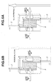
- Figs. 5A, 5B, 6A, and 6C show a fifth preferred embodiment of the state sensing apparatus according to the present invention.
- a liquid crystal cell As typically shown in Fig. 5A, a liquid crystal cell (or liquid crystal device 8) is provided with electrodes, a liquid crystal material, a light introducing window (light inlet) 8A, and a light outlet window 8B (light outlet).
- the electrodes of the liquid crystal device are connected in parallel to the lithium ion battery as typically shown in Fig. 5A.
- Fig. 7 shows a discharge curve of the battery used in the fifth embodiment.
- a longitudinal axis denotes a battery terminal voltage and a lateral axis denotes a discharge quantity.
- a voltage Ve shown in Fig. 7 denotes a prescribed discharge terminating voltage in an operation mode presumed in the battery system shown in Fig. 5A through 6B.
- the discharge terminating voltage means a voltage prescribed that the discharge of the battery is stopped at a time point at which the applied voltage has arrived.
- the voltage Va is a voltage at which the liquid crystal composition is oriented (or twisted) to change a light-transmissive (or light transparent) characteristic.
- the voltage Va is usually set to be lower than the voltage Ve.
- the above-described voltage Va at which the orientation of the liquid crystal is varied is set to be higher than the voltage Vd.
- the orientation of the liquid crystal composition of the liquid crystal device 8 is changed so that the introduced light cannot be transmitted through the liquid crystal device 8.
- the battery state sensing apparatus can prevent such a phenomenon that the discharge of the battery is continued with time so that the battery falls in an excessive discharge region such as to cause, for example, a deterioration of the battery.
- Fig. 8 shows a sixth preferred embodiment of the battery state sensing apparatus according to the present invention applicable to a cell group system.
- a couple of light source 10 and photo sensor 4 are prepared by connecting light tranmitting portions of respective liquid crystal devices 11 via such an optical wave guide 12 as an optical fiber, the respective liquid crystal devices 11 being connected in parallel to corresponding batteries (,i.e., connected across positive and negative electrodes of the corresponding battery).
- the state sensing apparatus can sense its excessive discharge state, can maintain its insulating characteristic, and can provide a simple system configuration.
- any cell 9 is charged with the prescribed voltage Va or higher, the light from the light source 10 becomes incident on the photo sensor 4 optically connected to one end of the optical fiber (optical wave guide) 12 without interruption (or shutter) by any liquid crystal device 11 connected in parallel to the corresponding cell 9.
- any cell 9 would be reduced at a discharge terminating period of the cell group.
- the corresponding liquid crystal device 11 connected in parallel thereto does not transmit the light but interrupt the light source 10 cannot arrive at the end terminal of the optical fiber 12 at which the photo sensor 4 is installed.
- the battery state sensing apparatus in the sixth embodiment described above can assuredly sense the voltage of any cell 9 which becomes equal to or lower than the prescribed voltage Va.
- the battery state sensing apparatus can be carried out without large consumption of battery energy.
- the state of the battery is the excessive discharge state of the battery (the multi-cell structure) without consumption of the residual energy in each cell 9.
- Figs. 9A and 10 show a seventh preferred embodiment of the battery state sensing apparatus according to the present invention.
- a photo shutter section 23, viz., the liquid crystal device 8, e.g., described in the fifth embodiment is connected in parallel to each cell 9 in such a manner that one electrode thereof is coupled to the positive electrode 2 of each cell and the other electrode thereof is coupled to the negative electrode 3 of each cell, the light inlet window 8A and light outlet window 8B being provided.
- a condensing foil 21 is adhered onto part of an upper surface except the light inlet window.
- Another condensing foil 22 is adhered onto part of a lower surface except the light outlet window 8B of the liquid crystal device, viz., the light shutter section 23.
- the internal structure of each cell of the cell group is the same as that of the second embodiment shown in Fig. 3.
- the seventh embodiment is a combination of the sixth embodiment with the second embodiment. Therefore, both of the excessive charge and the excessive discharge states of the cell group, viz., the battery (multi-cell structure) can be sensed, as appreciated from Fig. 9A.
- each cell 9 is connected in series with one another to form the battery in the case of Fig. 9A.
- Fig. 9B shows an alternative of the seventh preferred embodiment of the battery state sensing apparatus.
- each cell 9 is connected in parallel to one another to form the cell group.
- both excessive charge and discharge states of the cell group can be sensed as in the same way as in the seventh embodiment.
- a light superposing section 40 to superpose the light from the respective liquid crystal devices (LQD) 11 is needed in the optical wave guide 12 before the photo sensor 4.
- the cell is a solid-state cell whose ion conductive portion (layer) is made of either a high molecular conductive material or inorganic ion conductor (conductive material), the battery is a lithium ion secondary battery in which a lithium ion is used as medium transporting positive charges, the positive electrode of the cell is made of LiMnO 2 (Lithium Manganese Dioxide), and the negative electrode of the cell is made of hard carbon.
- the ion conductive portion layer
- the battery is a lithium ion secondary battery in which a lithium ion is used as medium transporting positive charges
- the positive electrode of the cell is made of LiMnO 2 (Lithium Manganese Dioxide)
- the negative electrode of the cell is made of hard carbon.
- the light emitting device specifically includes the light emitting diode and the voltage-responsive optical sensing device means, so-called, an electro-optical device such as the light emitting device and the liquid crystal device.
Landscapes
- Engineering & Computer Science (AREA)
- Manufacturing & Machinery (AREA)
- Chemical & Material Sciences (AREA)
- Chemical Kinetics & Catalysis (AREA)
- Electrochemistry (AREA)
- General Chemical & Material Sciences (AREA)
- Secondary Cells (AREA)
Applications Claiming Priority (4)
| Application Number | Priority Date | Filing Date | Title |
|---|---|---|---|
| JP2000058077A JP2001250591A (ja) | 2000-03-03 | 2000-03-03 | 電池状態検知素子構成 |
| JP2000058078 | 2000-03-03 | ||
| JP2000058077 | 2000-03-03 | ||
| JP2000058078A JP2001250592A (ja) | 2000-03-03 | 2000-03-03 | 低消費電力型電池状態検知システム |
Publications (1)
| Publication Number | Publication Date |
|---|---|
| EP1130672A2 true EP1130672A2 (fr) | 2001-09-05 |
Family
ID=26586683
Family Applications (1)
| Application Number | Title | Priority Date | Filing Date |
|---|---|---|---|
| EP01104860A Withdrawn EP1130672A2 (fr) | 2000-03-03 | 2001-02-28 | Indicateur de charge de pile |
Country Status (2)
| Country | Link |
|---|---|
| US (1) | US6384607B2 (fr) |
| EP (1) | EP1130672A2 (fr) |
Cited By (6)
| Publication number | Priority date | Publication date | Assignee | Title |
|---|---|---|---|---|
| FR2873460A1 (fr) * | 2004-07-21 | 2006-01-27 | Saint Gobain | Systeme electrochimique a electrolyte non oxyde |
| WO2006048732A1 (fr) * | 2004-11-02 | 2006-05-11 | Nissan Motor Co., Ltd. | Element d'accumulateur bipolaire et ensemble accumulateur pour vehicules |
| WO2007033690A1 (fr) * | 2005-09-20 | 2007-03-29 | Metabowerke Gmbh | Accumulateur et outil electrique a main |
| EP1833107A1 (fr) | 2006-03-09 | 2007-09-12 | Nissan Motor Co., Ltd. | Améliorations de ou associées aux batteries |
| EP2260534A1 (fr) * | 2008-03-05 | 2010-12-15 | Opalux Incorporated | Indicateur de propriété électrique à cristaux photoniques |
| CN107505573A (zh) * | 2017-07-28 | 2017-12-22 | 郑州比克电池有限公司 | 一种判别锂电池内部负极片掉料的方法 |
Families Citing this family (16)
| Publication number | Priority date | Publication date | Assignee | Title |
|---|---|---|---|---|
| US6822456B2 (en) | 2002-07-26 | 2004-11-23 | David M. Allen | Bi-metallic test switch |
| US8222868B2 (en) * | 2008-04-02 | 2012-07-17 | Techtronic Power Tools Technology Limited | Battery tester for rechargeable power tool batteries |
| JPWO2010035369A1 (ja) * | 2008-09-25 | 2012-02-16 | パナソニック株式会社 | 発光素子及び表示装置 |
| US10074879B2 (en) * | 2009-07-29 | 2018-09-11 | Deep Science, Llc | Instrumented fluid-surfaced electrode |
| US9054397B2 (en) * | 2009-08-11 | 2015-06-09 | Amphenol Thermometrics, Inc. | Battery cell with integrated sensing platform |
| JP4580037B1 (ja) * | 2010-03-29 | 2010-11-10 | エンパイア テクノロジー ディベロップメント エルエルシー | 電池システム、及び電池の安全警報システム |
| JP4580038B1 (ja) | 2010-04-27 | 2010-11-10 | エンパイア テクノロジー ディベロップメント エルエルシー | 電池システム、及び電池の安全警報システム |
| WO2012057787A1 (fr) * | 2010-10-29 | 2012-05-03 | Empire Technology Development Llc | Appareil de stockage d'énergie |
| DE102011083167A1 (de) * | 2011-09-22 | 2013-03-28 | Robert Bosch Gmbh | Energiespeichersystem und Zustandserkennungssystem umfassend das Energiespeichersystem |
| US9570781B2 (en) * | 2012-08-10 | 2017-02-14 | Battelle Memorial Institute | Optical waveguide methods for detecting internal faults in operating batteries |
| US10211489B2 (en) | 2012-08-10 | 2019-02-19 | Battelle Memorial Institute | Integral light sources and detectors for an optical sensor to detect battery faults |
| CN104541387A (zh) | 2012-08-10 | 2015-04-22 | 巴特勒纪念研究院 | 电池健康的光学监测 |
| JP6112094B2 (ja) * | 2014-10-22 | 2017-04-12 | トヨタ自動車株式会社 | 全固体電池システム |
| US10177421B2 (en) * | 2015-02-12 | 2019-01-08 | Battelle Memorial Institute | Battery cell structure with limited cell penetrations |
| DE102018212837A1 (de) * | 2018-08-01 | 2020-02-06 | Audi Ag | Vorrichtung und Verfahren zur optischen Spannungsdetektion bei Brennstoffzellen |
| TW202337732A (zh) * | 2022-02-16 | 2023-10-01 | 義大利商馬普斯公司 | 用於監測電能儲存裝置之健康狀態的系統和方法、以及包括該系統的電能儲存裝置 |
Family Cites Families (2)
| Publication number | Priority date | Publication date | Assignee | Title |
|---|---|---|---|---|
| JP3223824B2 (ja) | 1996-12-26 | 2001-10-29 | 三菱電機株式会社 | リチウムイオン二次電池 |
| JP3716618B2 (ja) | 1998-05-14 | 2005-11-16 | 日産自動車株式会社 | 組電池の制御装置 |
-
2001
- 2001-02-28 EP EP01104860A patent/EP1130672A2/fr not_active Withdrawn
- 2001-03-02 US US09/796,555 patent/US6384607B2/en not_active Expired - Fee Related
Cited By (15)
| Publication number | Priority date | Publication date | Assignee | Title |
|---|---|---|---|---|
| WO2006018568A2 (fr) * | 2004-07-21 | 2006-02-23 | Saint-Gobain Glass France | Systeme electrochimique a electrolyte non oxyde |
| FR2873460A1 (fr) * | 2004-07-21 | 2006-01-27 | Saint Gobain | Systeme electrochimique a electrolyte non oxyde |
| WO2006018568A3 (fr) * | 2004-07-21 | 2007-04-05 | Saint Gobain | Systeme electrochimique a electrolyte non oxyde |
| CN1950967B (zh) * | 2004-11-02 | 2010-05-12 | 日产自动车株式会社 | 双极电池单元、组合电池、车辆和双极电池单元制作方法 |
| WO2006048732A1 (fr) * | 2004-11-02 | 2006-05-11 | Nissan Motor Co., Ltd. | Element d'accumulateur bipolaire et ensemble accumulateur pour vehicules |
| US7989106B2 (en) | 2004-11-02 | 2011-08-02 | Nissan Motor Co., Ltd. | Bipolar battery cell and assembled battery for a vehicle |
| WO2007033690A1 (fr) * | 2005-09-20 | 2007-03-29 | Metabowerke Gmbh | Accumulateur et outil electrique a main |
| US8211560B2 (en) | 2005-09-20 | 2012-07-03 | Metabowerke Gmbh | Battery pack and hand-held power tool |
| US7609029B2 (en) | 2006-03-09 | 2009-10-27 | Nissan Motor Co., Ltd. | Battery, assembled battery unit, vehicle equipped with battery, and battery voltage adjusting method |
| EP1833107A1 (fr) | 2006-03-09 | 2007-09-12 | Nissan Motor Co., Ltd. | Améliorations de ou associées aux batteries |
| EP2913878A1 (fr) * | 2006-03-09 | 2015-09-02 | Nissan Motor Co., Ltd. | Améliorations de ou associées aux batteries |
| EP2260534A1 (fr) * | 2008-03-05 | 2010-12-15 | Opalux Incorporated | Indicateur de propriété électrique à cristaux photoniques |
| EP2260534A4 (fr) * | 2008-03-05 | 2014-04-09 | Opalux Inc | Indicateur de propriété électrique à cristaux photoniques |
| US9130227B2 (en) | 2008-03-05 | 2015-09-08 | Opalux Incorporated | Photonic crystal electrical property indicator |
| CN107505573A (zh) * | 2017-07-28 | 2017-12-22 | 郑州比克电池有限公司 | 一种判别锂电池内部负极片掉料的方法 |
Also Published As
| Publication number | Publication date |
|---|---|
| US6384607B2 (en) | 2002-05-07 |
| US20010019794A1 (en) | 2001-09-06 |
Similar Documents
| Publication | Publication Date | Title |
|---|---|---|
| US6384607B2 (en) | Battery state sensing apparatus | |
| US6410185B1 (en) | Battery device for loading on moving body | |
| US20040095093A1 (en) | Battery pack | |
| US9515309B2 (en) | Cylindrical secondary battery pack | |
| KR101984314B1 (ko) | 이차전지 | |
| US8785021B2 (en) | Battery pack | |
| KR102260834B1 (ko) | 이차전지 | |
| US9190646B2 (en) | Rechargeable battery | |
| KR102046005B1 (ko) | 듀얼 셀 보호 ic 및 이를 포함하는 배터리 모듈 | |
| KR20160109428A (ko) | 배터리 팩 | |
| CN107996006B (zh) | 包括导线固定肋的电池模块 | |
| CN1391109A (zh) | 电池状态检测电路 | |
| US8013573B2 (en) | Battery pack that provides precise voltage measurements of batteries when safety switch is present | |
| KR20200086933A (ko) | 이차전지 및 그 제조방법 | |
| KR100904375B1 (ko) | 퓨즈 장착 전지 카트리지와 그것을 포함하는 전지 모듈 | |
| JP2007294281A (ja) | 電池パック | |
| US20070037052A1 (en) | Battery module and method of making the same | |
| JP2004265722A (ja) | 二次電池 | |
| US20210098793A1 (en) | Power storage element, power storage cell, and power storage and discharge system | |
| JP2009231060A (ja) | 電池パック | |
| US20240030571A1 (en) | Electrolyte Reinjection Method and Electrolyte-Reinjectable Secondary Battery | |
| US20220166234A1 (en) | Protective circuit, energy storage apparatus, and control method for protective circuit | |
| KR20200072458A (ko) | 파우치형 이차전지 | |
| JP3045291B2 (ja) | 情報処理装置 | |
| KR100731415B1 (ko) | 캡 조립체 및 이를 채용한 각형 이차전지 |
Legal Events
| Date | Code | Title | Description |
|---|---|---|---|
| PUAI | Public reference made under article 153(3) epc to a published international application that has entered the european phase |
Free format text: ORIGINAL CODE: 0009012 |
|
| 17P | Request for examination filed |
Effective date: 20010228 |
|
| AK | Designated contracting states |
Kind code of ref document: A2 Designated state(s): AT BE CH CY DE DK ES FI FR GB GR IE IT LI LU MC NL PT SE TR |
|
| AX | Request for extension of the european patent |
Free format text: AL;LT;LV;MK;RO;SI |
|
| STAA | Information on the status of an ep patent application or granted ep patent |
Free format text: STATUS: THE APPLICATION HAS BEEN WITHDRAWN |
|
| 18W | Application withdrawn |
Effective date: 20041007 |