EP1130167A2 - Bollard - Google Patents
Bollard Download PDFInfo
- Publication number
- EP1130167A2 EP1130167A2 EP01105289A EP01105289A EP1130167A2 EP 1130167 A2 EP1130167 A2 EP 1130167A2 EP 01105289 A EP01105289 A EP 01105289A EP 01105289 A EP01105289 A EP 01105289A EP 1130167 A2 EP1130167 A2 EP 1130167A2
- Authority
- EP
- European Patent Office
- Prior art keywords
- bollard
- embedding sleeve
- sleeve
- conical
- connecting piece
- Prior art date
- Legal status (The legal status is an assumption and is not a legal conclusion. Google has not performed a legal analysis and makes no representation as to the accuracy of the status listed.)
- Granted
Links
Images


Classifications
-
- E—FIXED CONSTRUCTIONS
- E01—CONSTRUCTION OF ROADS, RAILWAYS, OR BRIDGES
- E01F—ADDITIONAL WORK, SUCH AS EQUIPPING ROADS OR THE CONSTRUCTION OF PLATFORMS, HELICOPTER LANDING STAGES, SIGNS, SNOW FENCES, OR THE LIKE
- E01F15/00—Safety arrangements for slowing, redirecting or stopping errant vehicles, e.g. guard posts or bollards; Arrangements for reducing damage to roadside structures due to vehicular impact
- E01F15/003—Individual devices arranged in spaced relationship, e.g. buffer bollards
-
- E—FIXED CONSTRUCTIONS
- E01—CONSTRUCTION OF ROADS, RAILWAYS, OR BRIDGES
- E01F—ADDITIONAL WORK, SUCH AS EQUIPPING ROADS OR THE CONSTRUCTION OF PLATFORMS, HELICOPTER LANDING STAGES, SIGNS, SNOW FENCES, OR THE LIKE
- E01F9/00—Arrangement of road signs or traffic signals; Arrangements for enforcing caution
- E01F9/60—Upright bodies, e.g. marker posts or bollards; Supports for road signs
- E01F9/623—Upright bodies, e.g. marker posts or bollards; Supports for road signs characterised by form or by structural features, e.g. for enabling displacement or deflection
- E01F9/631—Upright bodies, e.g. marker posts or bollards; Supports for road signs characterised by form or by structural features, e.g. for enabling displacement or deflection specially adapted for breaking, disengaging, collapsing or permanently deforming when deflected or displaced, e.g. by vehicle impact
- E01F9/638—Upright bodies, e.g. marker posts or bollards; Supports for road signs characterised by form or by structural features, e.g. for enabling displacement or deflection specially adapted for breaking, disengaging, collapsing or permanently deforming when deflected or displaced, e.g. by vehicle impact by connection of stud-and-socket type, e.g. spring-loaded
-
- E—FIXED CONSTRUCTIONS
- E01—CONSTRUCTION OF ROADS, RAILWAYS, OR BRIDGES
- E01F—ADDITIONAL WORK, SUCH AS EQUIPPING ROADS OR THE CONSTRUCTION OF PLATFORMS, HELICOPTER LANDING STAGES, SIGNS, SNOW FENCES, OR THE LIKE
- E01F9/00—Arrangement of road signs or traffic signals; Arrangements for enforcing caution
- E01F9/60—Upright bodies, e.g. marker posts or bollards; Supports for road signs
- E01F9/658—Upright bodies, e.g. marker posts or bollards; Supports for road signs characterised by means for fixing
- E01F9/673—Upright bodies, e.g. marker posts or bollards; Supports for road signs characterised by means for fixing for holding sign posts or the like
- E01F9/685—Subsoil means, e.g. foundations
Definitions
- the invention relates to a bollard in Preamble of claim 1 specified genus.
- Such bollards are used as safety posts in places. e.g. Parking lots or in pedestrian zones or as a fence around Buildings or monuments.
- the external form of such Bollards generally match the architectural style of the area customized. Newer constructions are sometimes with the help of a Hydrant key or the like. detachably anchored.
- the invention has for its object a simple Anchored and interchangeable, but not easily to create removable bollard.
- This mounting system for bollards can also be used for Signs, benches, trash cans, etc. can be used.
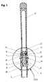
- the bollard shown in Fig. 1 consists of the following Individual parts: an embedding sleeve 1 to be embedded in concrete, a connector 2, a bollard top 3, two Clamping cones 4 and 5, a screw 6 and a nut (not shown), which in the one clamping cone, here e.g. 5, is used.
- the connecting piece 2 After anchoring the embedding sleeve 1, advantageously in concrete (not shown) shown individually in Figs. 5 and 6 is the connecting piece 2 via longitudinal grooves 7 (see Fig. 9 and 10) inserted in the embedding sleeve 1 and by rotation coupled by 90 ° like a bayonet. Cams 8 engage Connector 2 in a corresponding inner circumferential groove 9 of the Embedding sleeve 1.
- the configuration of the clamping cones 4, 5 is shown in FIGS. 3 and 4 shown.
- the screw-side clamping cone 4 has one Through hole 13 for the screw 6, during the nut-side clamping cone 5 in the described Embodiment a somewhat conical hexagon 14 for non-positive clamping of the nut matching screw 6 (not shown).
- the mother becomes so deep in that Hexagon socket 14 of the clamping cone 5 added that a Hexagon wrench of conventional type (not shown) yet be inserted into the hexagon socket 14 above the nut can counter to if the screw 6, the one Polygonal head, e.g. Triangular or square, with one appropriate special key (not shown) tightened becomes.
- a cover 16 can also be provided for the bollard is shown in Fig. 13 in side view and instead of Connector 2 and the bollard top 3 bayonet in the embedding sleeve 1 is locked when the bollard is not is needed and after loosening the screw 6 Bollard top 3 together with the connector 2 after turning back has been removed from the embedding sleeve 1 by 90 °.
- the lid 16 also has cams 17 for the bayonet catch in contrast to the cams 8 of the connector 2 in the Inner circumferential groove 9 of the embedding sleeve 1 hardly has any axial play to have.
- rainwater infiltration Embedding sleeve 1 is hollow and towards the connecting piece 2 Has axial bore 18.
- the connector 2 can also have a circumferential groove 19 as a predetermined breaking point.
Landscapes
- Architecture (AREA)
- Civil Engineering (AREA)
- Structural Engineering (AREA)
- Engineering & Computer Science (AREA)
- Refuge Islands, Traffic Blockers, Or Guard Fence (AREA)
- Thin Film Transistor (AREA)
- Rod-Shaped Construction Members (AREA)
- Recrystallisation Techniques (AREA)
- Building Environments (AREA)
- Forms Removed On Construction Sites Or Auxiliary Members Thereof (AREA)
- Medicines Containing Material From Animals Or Micro-Organisms (AREA)
- Pharmaceuticals Containing Other Organic And Inorganic Compounds (AREA)
- Led Devices (AREA)
- Amplifiers (AREA)
- Light Receiving Elements (AREA)
- Road Signs Or Road Markings (AREA)
Abstract
Description
Die Erfindung bezieht sich auf einen Poller der im
Oberbegriff des Patentanspruchs 1 angegebenen Gattung.The invention relates to a bollard in
Preamble of
Solche Poller werden als Sicherungspfosten auf Plätzen. z.B. Parkplätzen oder in Fußgängerzonen oder als Umzäunung von Gebäuden oder Denkmälern verwendet. Die äußere Form solcher Poller wird im allgemeinen dem jeweiligen Baustil der Umgebung angepaßt. Neuere Konstruktionen sind zuweilen mit Hilfe eines Hydrantenschlüssels o.dgl. lösbar verankert.Such bollards are used as safety posts in places. e.g. Parking lots or in pedestrian zones or as a fence around Buildings or monuments. The external form of such Bollards generally match the architectural style of the area customized. Newer constructions are sometimes with the help of a Hydrant key or the like. detachably anchored.
Der Erfindung liegt die Aufgabe zugrunde, einen auf einfache Weise verankerbaren und austauschbaren, aber nicht ohne weiteres lösbaren Poller zu schaffen.The invention has for its object a simple Anchored and interchangeable, but not easily to create removable bollard.
Diese Aufgabe wird erfindungsgemäß durch die
Kennzeichnungsmerkmale des Patentanspruchs 1 gelöst.This object is achieved by the
Characteristic features of
Zweckmäßige Weiterbildungen der Erfindung sind Gegenstand der Unteransprüche.Appropriate developments of the invention are the subject of subclaims.
Dieses Befestigungssystem für Poller kann ebenfalls für Schilder, Bänke, Abfalleimer, etc. verwendet werden.This mounting system for bollards can also be used for Signs, benches, trash cans, etc. can be used.
Ein Ausführungsbeispiel des erfindungsgemäßen Pollers ist in den Zeichnungen dargestellt. Dabei zeigt
- Fig. 1
- im Längsschnitt den fertig montierten Poller,
- Fig. 2
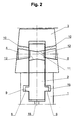
- in schematischer Einzeldarstellung das Verbindungsstück im Zusammenwirken mit dem Polleroberteil und der Einbetthülse vor dem Anziehen der Klemmkegel,
- Fig. 3
- perspektivisch den schraubenseitigen Klemmkegel,
- Fig. 4
- perspektivisch den mutterseitigen Klemmkegel,
- Fig. 5
- perspektivisch das Verbindungsstück,
- Fig. 6
- einen Längsschnitt des Verbindungsstücks,
- Fig. 7
- perspektivisch die Einbetthülse,
- Fig. 8
- einen Längsschnitt der Einbetthülse,
- Fig. 9
- einen weiteren Längsschnitt der Einbetthülse,
- Fig. 10
- einen Schnitt nach der Linie X-X in Fig. 11,
- Fig. 11
- perspektivisch das Polleroberteil,
- Fig. 12
- einen Längsschnitt des Polleroberteils nach Fig. 9,
- Fig. 13
- in Seitenansicht einen zugehörigen Deckel,
- Fig. 14
- einen Ausschnitt XIV aus Fig. 1 nach dem Anziehen der Klemmkegel und
- Fig. 15
- einen Schnitt nach der Linie XV-XV in Fig. 14.
- Fig. 1
- in longitudinal section the fully assembled bollard,
- Fig. 2
- in a schematic individual illustration, the connecting piece in cooperation with the bollard top and the embedding sleeve before tightening the clamping cone,
- Fig. 3
- perspective the screw-side clamping cone,
- Fig. 4
- perspective the nut-side clamping cone,
- Fig. 5
- perspective the connector,
- Fig. 6
- a longitudinal section of the connector,
- Fig. 7
- perspective the embedding sleeve,
- Fig. 8
- a longitudinal section of the embedding sleeve,
- Fig. 9
- another longitudinal section of the embedding sleeve,
- Fig. 10
- 11 shows a section along the line XX in FIG. 11,
- Fig. 11
- perspective the bollard top,
- Fig. 12
- 9 shows a longitudinal section of the bollard top according to FIG. 9,
- Fig. 13
- in side view an associated lid,
- Fig. 14
- a section XIV of Fig. 1 after tightening the clamping cone and
- Fig. 15
- a section along the line XV-XV in Fig. 14th
Der in Fig. 1 dargestellte Poller besteht aus folgenden
Einzelteilen: einer in Beton einzubettenden Einbetthülse 1,
einem Verbindungsstück 2, einem Polleroberteil 3, zwei
Klemmkegeln 4 und 5, einer Schraube 6 und einer Mutter (nicht
dargestellt), die in den einen Klemmkegel, hier z.B. 5,
eingesetzt wird.The bollard shown in Fig. 1 consists of the following
Individual parts: an embedding
Nach dem Verankern der Einbetthülse 1, vorteilhaft in Beton
(nicht dargestellt), die in den Fig. 5 und 6 einzeln dargestellt
ist, wird das Verbindungsstück 2 über Längsnuten 7 (siehe Fig. 9
und 10) in die Einbetthülse 1 eingesteckt und durch eine Drehung
um 90° bajonettartig gekuppelt. Dabei greifen Nocken 8 des
Verbindungsstücks 2 in eine entsprechende Innenumfangsnut 9 der
Einbetthülse 1 ein.After anchoring the embedding
Danach wird das Polleroberteil 3 auf das Verbindungsstück 2
so aufgesetzt, daß konische Querbohrungen 10 des Polleroberteils
3 (siehe Fig. 11 und 12) mit einer Querbohrung 11 des
Verbindungsstücks 2 fluchten, die an beiden Enden jeweils eine
konische Erweiterung 12 aufweist.Then the
Daraufhin werden die beiden Klemmkegel 4 und 5 von beiden
Seiten des Polleroberteils 3 in die konischen Querbohrungen 10
desselben so eingesetzt, daß die Klemmkegel 4, 5 bereits ein
Stück in die konischen Erweiterungen 12 der Querbohrung 11 des
Verbindungsstücks 2 eingreifen.Then the two
Die Ausbildung der Klemmkegel 4, 5 ist in den Fig. 3 und 4
dargestellt. Der schraubenseitige Klemmkegel 4 weist eine
Durchgangsbohrung 13 für die Schraube 6 auf, während der
mutterseitige Klemmkegel 5 in dem beschriebenen
Ausführungsbeispiel einen etwas konischen Innensechskant 14 zum
kraftschlüssigen Einklemmen der zur Schraube 6 passenden Mutter
(nicht dargestellt) aufweist. Die Mutter wird so tief in dem
Innensechskant 14 des Klemmkegels 5 aufgenommen, daß ein
Sechskantschlüssel herkömmlichen Typs (nicht dargestellt) noch
über der Mutter in den Innensechskant 14 eingesteckt werden
kann, um gegenzuhalten, wenn die Schraube 6, die einen
Mehrkantkopf, z.B. Dreikant oder Vierkant, aufweist, mit einem
entsprechenden Spezialschlüssel (nicht dargestellt) angezogen
wird.The configuration of the clamping
Beim Anziehen der Schraube 6 werden die Klemmkegel 4, 5, die
zunächst mit Spiel in der jeweiligen konischen Querbohrung 10
des Polleroberteils 3 und in den konischen Erweiterungen 12 der
Querbohrung 11 des Verbindungsstücks 2 sitzen (siehe Fig. 2),
nach innen gezogen, um durch eine Art Keilwirkung das
Verbindungsstück 2 nach oben zu ziehen und gleichzeitig das
Polleroberteil 3 nach unten auf die Einbetthülse 1 zu drücken.
Dieser Vorgang wird begrenzt durch den Anschlag der Nocken 8 des
Verbindungsstücks 2 an der oberen Wand 15 der Innenumfangsnut 9
der Einbetthülse 1 und wird durch die schematische Darstellung
in Fig. 2 verständlich. In den Fig. 14 und 15, die einen
Ausschnitt XIV aus Fig. 1 zeigen, sind die Klemmkeile 4, 5 durch
die Schraube und Mutter (hier nicht dargestellt) festgezogen.When tightening the
Zu dem Poller kann noch ein Deckel 16 vorgesehen sein, der
in Fig. 13 in Seitenansicht dargestellt ist und anstelle des
Verbindungsstücks 2 und des Polleroberteils 3 bajonettartig in
der Einbetthülse 1 verriegelt wird, wenn der Poller nicht
benötigt wird und nachdem nach Lockern der Schraube 6 das
Polleroberteil 3 mitsamt dem Verbindungsstück 2 nach Rückdrehung
um 90° aus der Einbetthülse 1 herausgenommen wurde. Der Deckel
16 weist für den Bajonettverschluß ebenfalls Nocken 17 auf, die
im Gegensatz zu den Nocken 8 des Verbindungsstücks 2 in der
Innenumfangsnut 9 der Einbetthülse 1 kaum ein axiales Spiel
haben.A
Zu erwähnen wäre noch, daß zum Absickern von Regenwasser die
Einbetthülse 1 hohl ist und zum Verbindungsstück 2 hin eine
Axialbohrung 18 aufweist. Das Verbindungsstück 2 kann ferner
einen Umfangseinstich 19 als Sollbruchstelle aufweisen.It should also be mentioned that for rainwater
Claims (5)
Priority Applications (1)
| Application Number | Priority Date | Filing Date | Title |
|---|---|---|---|
| SI200130624T SI1130167T1 (en) | 2000-03-03 | 2001-03-05 | Bollard |
Applications Claiming Priority (2)
| Application Number | Priority Date | Filing Date | Title |
|---|---|---|---|
| DE10010449A DE10010449C1 (en) | 2000-03-03 | 2000-03-03 | Bollard for car parks, fences, etc. has connector part between anchoring sleeve and upper part, locked in place by clamping cones tightened by special tool |
| DE10010449 | 2000-03-03 |
Publications (3)
| Publication Number | Publication Date |
|---|---|
| EP1130167A2 true EP1130167A2 (en) | 2001-09-05 |
| EP1130167A3 EP1130167A3 (en) | 2003-10-22 |
| EP1130167B1 EP1130167B1 (en) | 2006-06-21 |
Family
ID=7633414
Family Applications (1)
| Application Number | Title | Priority Date | Filing Date |
|---|---|---|---|
| EP01105289A Expired - Lifetime EP1130167B1 (en) | 2000-03-03 | 2001-03-05 | Bollard |
Country Status (7)
| Country | Link |
|---|---|
| EP (1) | EP1130167B1 (en) |
| AT (1) | ATE331085T1 (en) |
| DE (1) | DE10010449C1 (en) |
| DK (1) | DK1130167T3 (en) |
| ES (1) | ES2265368T3 (en) |
| PT (1) | PT1130167E (en) |
| SI (1) | SI1130167T1 (en) |
Families Citing this family (6)
| Publication number | Priority date | Publication date | Assignee | Title |
|---|---|---|---|---|
| FR2825740B1 (en) * | 2001-06-08 | 2006-09-29 | Caravagna Jean Luc | DEMONABLE PROTECTION BARRIER |
| ATE363008T1 (en) * | 2001-10-09 | 2007-06-15 | Wemas Gmbh | DEVICE FOR FIXING A BAKEAON TO A FOOTPLATE |
| DE10326680B4 (en) * | 2003-06-13 | 2006-01-19 | Lutz Barich | Flood protection wall |
| EP2039834B1 (en) | 2007-09-18 | 2012-11-14 | Lutz Barich | Fixing element for connecting urban objects such as bollards with and without lighting, street furniture, street signs, playground devices and similar with an embedded anchoring sleeve in the ground |
| DE102008045788A1 (en) | 2007-09-18 | 2009-03-26 | Lutz Barich | Fastening element for connecting official goods, has embedding sleeve inserted in ground, and two-part connection piece contains insertion part projecting in opening of object |
| DE102021102067B4 (en) | 2021-01-29 | 2023-07-13 | Lutz Barich | Arrangement of a device on a surface or a floor to form a demarcation or separation of surfaces, paths or the like. |
Citations (3)
| Publication number | Priority date | Publication date | Assignee | Title |
|---|---|---|---|---|
| DE1845138U (en) * | 1961-10-24 | 1962-01-18 | Vdo Schindling | HOLDING DEVICE FOR PARKING TIMERS. |
| US3802135A (en) * | 1970-08-27 | 1974-04-09 | E Weichenrieder | Hollow plastic break-away post |
| EP0176973A2 (en) * | 1984-10-02 | 1986-04-09 | Ingeborg Jöckel | Bollard mount |
Family Cites Families (1)
| Publication number | Priority date | Publication date | Assignee | Title |
|---|---|---|---|---|
| DE9210725U1 (en) * | 1992-08-11 | 1992-10-29 | Kuo, Mao-Te, Taipeh / T'ai-Pei, Tw |
-
2000
- 2000-03-03 DE DE10010449A patent/DE10010449C1/en not_active Expired - Lifetime
-
2001
- 2001-03-05 AT AT01105289T patent/ATE331085T1/en active
- 2001-03-05 SI SI200130624T patent/SI1130167T1/en unknown
- 2001-03-05 ES ES01105289T patent/ES2265368T3/en not_active Expired - Lifetime
- 2001-03-05 DK DK01105289T patent/DK1130167T3/en active
- 2001-03-05 EP EP01105289A patent/EP1130167B1/en not_active Expired - Lifetime
- 2001-03-05 PT PT01105289T patent/PT1130167E/en unknown
Patent Citations (3)
| Publication number | Priority date | Publication date | Assignee | Title |
|---|---|---|---|---|
| DE1845138U (en) * | 1961-10-24 | 1962-01-18 | Vdo Schindling | HOLDING DEVICE FOR PARKING TIMERS. |
| US3802135A (en) * | 1970-08-27 | 1974-04-09 | E Weichenrieder | Hollow plastic break-away post |
| EP0176973A2 (en) * | 1984-10-02 | 1986-04-09 | Ingeborg Jöckel | Bollard mount |
Also Published As
| Publication number | Publication date |
|---|---|
| ES2265368T3 (en) | 2007-02-16 |
| SI1130167T1 (en) | 2007-02-28 |
| DK1130167T3 (en) | 2006-10-30 |
| EP1130167B1 (en) | 2006-06-21 |
| EP1130167A3 (en) | 2003-10-22 |
| DE10010449C1 (en) | 2001-05-23 |
| ATE331085T1 (en) | 2006-07-15 |
| PT1130167E (en) | 2006-10-31 |
Similar Documents
| Publication | Publication Date | Title |
|---|---|---|
| EP2085521B1 (en) | Soil or rock anchor with an anchor pull made of one or more individual elements with corrosion protected anchor head design | |
| DE867909C (en) | Bolts for fastening objects in stone, concrete or the like. | |
| WO1997014371A1 (en) | Connector between an implant and an abutment | |
| EP0748422A1 (en) | Connecting element threaded on both sides | |
| DE60017433T2 (en) | CONNECTION DEVICE | |
| DE60031159T2 (en) | IMPRESSION CAP SYSTEM FOR THE USE IN DENTAL IMPLANTOLOGY | |
| EP2060703B1 (en) | Tie for shuttering | |
| DE10010449C1 (en) | Bollard for car parks, fences, etc. has connector part between anchoring sleeve and upper part, locked in place by clamping cones tightened by special tool | |
| DE4200096C2 (en) | Device for closing an opening in a panel | |
| DE102005022335A1 (en) | Formwork anchors and method for anchoring formwork elements and method for releasing a scaling anchor | |
| DE3339125C2 (en) | ||
| DE4336796C2 (en) | Device for connecting two adjacent wooden parts | |
| EP2455563A2 (en) | Headpiece for attachment to the front of a construction support and method | |
| EP1847666A1 (en) | Anchor device for tying of shuttering plates | |
| DE10326680B4 (en) | Flood protection wall | |
| AT407546B (en) | SPINDLE UNIT, ESPECIALLY FOR SHUTTERING | |
| DE3401426C2 (en) | Component set with a fastening device | |
| DE3910204A1 (en) | Railing | |
| EP2039834B1 (en) | Fixing element for connecting urban objects such as bollards with and without lighting, street furniture, street signs, playground devices and similar with an embedded anchoring sleeve in the ground | |
| EP3283694B1 (en) | Foundation anchoring for a working machine | |
| DE3403873A1 (en) | Apparatus for fastening a sleeve-shaped fixture on a formwork mould | |
| EP3913142A1 (en) | Urban furniture | |
| DE917189C (en) | Line connector for high and medium voltage lines as well as for local network and telephone lines | |
| EP1388628A2 (en) | Hinge with a lifting/lowering device for doors and windows, and whereby the height and the angle of the device are adjustable | |
| CH703046A2 (en) | Posts for use as part of e.g. temporary fence, during occasional event in cities, have thorn including non-thickened region that corresponds to post interior dimension and reciprocally provided with screwing head |
Legal Events
| Date | Code | Title | Description |
|---|---|---|---|
| PUAI | Public reference made under article 153(3) epc to a published international application that has entered the european phase |
Free format text: ORIGINAL CODE: 0009012 |
|
| AK | Designated contracting states |
Kind code of ref document: A2 Designated state(s): AT BE CH CY DE DK ES FI FR GB GR IE IT LI LU MC NL PT SE TR |
|
| AX | Request for extension of the european patent |
Free format text: AL;LT;LV;MK;RO;SI |
|
| PUAL | Search report despatched |
Free format text: ORIGINAL CODE: 0009013 |
|
| AK | Designated contracting states |
Kind code of ref document: A3 Designated state(s): AT BE CH CY DE DK ES FI FR GB GR IE IT LI LU MC NL PT SE TR |
|
| AX | Request for extension of the european patent |
Extension state: AL LT LV MK RO SI |
|
| 17P | Request for examination filed |
Effective date: 20040413 |
|
| AKX | Designation fees paid |
Designated state(s): AT BE CH DK ES FI FR GB GR IE IT LI LU NL PT SE TR |
|
| AXX | Extension fees paid |
Extension state: SI Payment date: 20040413 |
|
| REG | Reference to a national code |
Ref country code: DE Ref legal event code: 8566 |
|
| 17Q | First examination report despatched |
Effective date: 20040618 |
|
| GRAP | Despatch of communication of intention to grant a patent |
Free format text: ORIGINAL CODE: EPIDOSNIGR1 |
|
| GRAS | Grant fee paid |
Free format text: ORIGINAL CODE: EPIDOSNIGR3 |
|
| GRAA | (expected) grant |
Free format text: ORIGINAL CODE: 0009210 |
|
| AK | Designated contracting states |
Kind code of ref document: B1 Designated state(s): AT BE CH DK ES FI FR GB GR IE IT LI LU NL PT SE TR |
|
| AX | Request for extension of the european patent |
Extension state: SI |
|
| PG25 | Lapsed in a contracting state [announced via postgrant information from national office to epo] |
Ref country code: IT Free format text: LAPSE BECAUSE OF FAILURE TO SUBMIT A TRANSLATION OF THE DESCRIPTION OR TO PAY THE FEE WITHIN THE PRESCRIBED TIME-LIMIT;WARNING: LAPSES OF ITALIAN PATENTS WITH EFFECTIVE DATE BEFORE 2007 MAY HAVE OCCURRED AT ANY TIME BEFORE 2007. THE CORRECT EFFECTIVE DATE MAY BE DIFFERENT FROM THE ONE RECORDED. Effective date: 20060621 |
|
| REG | Reference to a national code |
Ref country code: GB Ref legal event code: FG4D Free format text: NOT ENGLISH |
|
| REG | Reference to a national code |
Ref country code: CH Ref legal event code: EP |
|
| REG | Reference to a national code |
Ref country code: IE Ref legal event code: FG4D Free format text: LANGUAGE OF EP DOCUMENT: GERMAN |
|
| REG | Reference to a national code |
Ref country code: CH Ref legal event code: NV Representative=s name: PA ALDO ROEMPLER |
|
| GBT | Gb: translation of ep patent filed (gb section 77(6)(a)/1977) |
Effective date: 20060912 |
|
| REG | Reference to a national code |
Ref country code: SE Ref legal event code: TRGR |
|
| REG | Reference to a national code |
Ref country code: DK Ref legal event code: T3 |
|
| REG | Reference to a national code |
Ref country code: PT Ref legal event code: SC4A Effective date: 20060810 |
|
| REG | Reference to a national code |
Ref country code: GR Ref legal event code: EP Ref document number: 20060403147 Country of ref document: GR |
|
| ET | Fr: translation filed | ||
| REG | Reference to a national code |
Ref country code: ES Ref legal event code: FG2A Ref document number: 2265368 Country of ref document: ES Kind code of ref document: T3 |
|
| PLBE | No opposition filed within time limit |
Free format text: ORIGINAL CODE: 0009261 |
|
| STAA | Information on the status of an ep patent application or granted ep patent |
Free format text: STATUS: NO OPPOSITION FILED WITHIN TIME LIMIT |
|
| 26N | No opposition filed |
Effective date: 20070322 |
|
| REG | Reference to a national code |
Ref country code: CH Ref legal event code: PCAR Free format text: ALDO ROEMPLER PATENTANWALT;BRENDENWEG 11 POSTFACH 154;9424 RHEINECK (CH) |
|
| PG25 | Lapsed in a contracting state [announced via postgrant information from national office to epo] |
Ref country code: TR Free format text: LAPSE BECAUSE OF FAILURE TO SUBMIT A TRANSLATION OF THE DESCRIPTION OR TO PAY THE FEE WITHIN THE PRESCRIBED TIME-LIMIT Effective date: 20060621 |
|
| REG | Reference to a national code |
Ref country code: FR Ref legal event code: PLFP Year of fee payment: 16 |
|
| REG | Reference to a national code |
Ref country code: FR Ref legal event code: PLFP Year of fee payment: 17 |
|
| REG | Reference to a national code |
Ref country code: FR Ref legal event code: PLFP Year of fee payment: 18 |
|
| PGFP | Annual fee paid to national office [announced via postgrant information from national office to epo] |
Ref country code: FI Payment date: 20190319 Year of fee payment: 19 Ref country code: FR Payment date: 20190326 Year of fee payment: 19 Ref country code: LU Payment date: 20190321 Year of fee payment: 19 Ref country code: GB Payment date: 20190325 Year of fee payment: 19 Ref country code: CH Payment date: 20190325 Year of fee payment: 19 Ref country code: IT Payment date: 20190321 Year of fee payment: 19 Ref country code: IE Payment date: 20190326 Year of fee payment: 19 |
|
| PGFP | Annual fee paid to national office [announced via postgrant information from national office to epo] |
Ref country code: NL Payment date: 20190321 Year of fee payment: 19 Ref country code: BE Payment date: 20190321 Year of fee payment: 19 Ref country code: SE Payment date: 20190325 Year of fee payment: 19 Ref country code: AT Payment date: 20190319 Year of fee payment: 19 Ref country code: DK Payment date: 20190325 Year of fee payment: 19 Ref country code: GR Payment date: 20190319 Year of fee payment: 19 |
|
| PGFP | Annual fee paid to national office [announced via postgrant information from national office to epo] |
Ref country code: ES Payment date: 20190424 Year of fee payment: 19 |
|
| PGFP | Annual fee paid to national office [announced via postgrant information from national office to epo] |
Ref country code: PT Payment date: 20200228 Year of fee payment: 20 |
|
| REG | Reference to a national code |
Ref country code: FI Ref legal event code: MAE |
|
| PG25 | Lapsed in a contracting state [announced via postgrant information from national office to epo] |
Ref country code: FI Free format text: LAPSE BECAUSE OF NON-PAYMENT OF DUE FEES Effective date: 20200305 |
|
| REG | Reference to a national code |
Ref country code: CH Ref legal event code: PL |
|
| REG | Reference to a national code |
Ref country code: DK Ref legal event code: EBP Effective date: 20200331 |
|
| REG | Reference to a national code |
Ref country code: NL Ref legal event code: MM Effective date: 20200401 |
|
| REG | Reference to a national code |
Ref country code: AT Ref legal event code: MM01 Ref document number: 331085 Country of ref document: AT Kind code of ref document: T Effective date: 20200305 |
|
| REG | Reference to a national code |
Ref country code: BE Ref legal event code: MM Effective date: 20200331 |
|
| PG25 | Lapsed in a contracting state [announced via postgrant information from national office to epo] |
Ref country code: NL Free format text: LAPSE BECAUSE OF NON-PAYMENT OF DUE FEES Effective date: 20200401 Ref country code: LU Free format text: LAPSE BECAUSE OF NON-PAYMENT OF DUE FEES Effective date: 20200305 |
|
| PG25 | Lapsed in a contracting state [announced via postgrant information from national office to epo] |
Ref country code: LI Free format text: LAPSE BECAUSE OF NON-PAYMENT OF DUE FEES Effective date: 20200331 Ref country code: GR Free format text: LAPSE BECAUSE OF NON-PAYMENT OF DUE FEES Effective date: 20201008 Ref country code: AT Free format text: LAPSE BECAUSE OF NON-PAYMENT OF DUE FEES Effective date: 20200305 Ref country code: IE Free format text: LAPSE BECAUSE OF NON-PAYMENT OF DUE FEES Effective date: 20200305 Ref country code: FR Free format text: LAPSE BECAUSE OF NON-PAYMENT OF DUE FEES Effective date: 20200331 Ref country code: SE Free format text: LAPSE BECAUSE OF NON-PAYMENT OF DUE FEES Effective date: 20200306 Ref country code: CH Free format text: LAPSE BECAUSE OF NON-PAYMENT OF DUE FEES Effective date: 20200331 |
|
| PG25 | Lapsed in a contracting state [announced via postgrant information from national office to epo] |
Ref country code: BE Free format text: LAPSE BECAUSE OF NON-PAYMENT OF DUE FEES Effective date: 20200331 |
|
| GBPC | Gb: european patent ceased through non-payment of renewal fee |
Effective date: 20200305 |
|
| PG25 | Lapsed in a contracting state [announced via postgrant information from national office to epo] |
Ref country code: GB Free format text: LAPSE BECAUSE OF NON-PAYMENT OF DUE FEES Effective date: 20200305 Ref country code: PT Free format text: LAPSE BECAUSE OF EXPIRATION OF PROTECTION Effective date: 20210315 Ref country code: DK Free format text: LAPSE BECAUSE OF NON-PAYMENT OF DUE FEES Effective date: 20200331 |
|
| REG | Reference to a national code |
Ref country code: ES Ref legal event code: FD2A Effective date: 20210726 |
|
| PG25 | Lapsed in a contracting state [announced via postgrant information from national office to epo] |
Ref country code: IT Free format text: LAPSE BECAUSE OF NON-PAYMENT OF DUE FEES Effective date: 20200305 |
|
| PG25 | Lapsed in a contracting state [announced via postgrant information from national office to epo] |
Ref country code: ES Free format text: LAPSE BECAUSE OF NON-PAYMENT OF DUE FEES Effective date: 20200306 |