EP1129930A2 - Stromversorgung für Fahrrad - Google Patents
Stromversorgung für Fahrrad Download PDFInfo
- Publication number
- EP1129930A2 EP1129930A2 EP01301580A EP01301580A EP1129930A2 EP 1129930 A2 EP1129930 A2 EP 1129930A2 EP 01301580 A EP01301580 A EP 01301580A EP 01301580 A EP01301580 A EP 01301580A EP 1129930 A2 EP1129930 A2 EP 1129930A2
- Authority
- EP
- European Patent Office
- Prior art keywords
- voltage
- terminal
- switch
- output terminal
- generator
- Prior art date
- Legal status (The legal status is an assumption and is not a legal conclusion. Google has not performed a legal analysis and makes no representation as to the accuracy of the status listed.)
- Granted
Links
Images


Classifications
-
- B—PERFORMING OPERATIONS; TRANSPORTING
- B62—LAND VEHICLES FOR TRAVELLING OTHERWISE THAN ON RAILS
- B62J—CYCLE SADDLES OR SEATS; AUXILIARY DEVICES OR ACCESSORIES SPECIALLY ADAPTED TO CYCLES AND NOT OTHERWISE PROVIDED FOR, e.g. ARTICLE CARRIERS OR CYCLE PROTECTORS
- B62J6/00—Arrangement of optical signalling or lighting devices on cycles; Mounting or supporting thereof; Circuits therefor
- B62J6/01—Electric circuits
-
- B—PERFORMING OPERATIONS; TRANSPORTING
- B62—LAND VEHICLES FOR TRAVELLING OTHERWISE THAN ON RAILS
- B62J—CYCLE SADDLES OR SEATS; AUXILIARY DEVICES OR ACCESSORIES SPECIALLY ADAPTED TO CYCLES AND NOT OTHERWISE PROVIDED FOR, e.g. ARTICLE CARRIERS OR CYCLE PROTECTORS
- B62J6/00—Arrangement of optical signalling or lighting devices on cycles; Mounting or supporting thereof; Circuits therefor
- B62J6/06—Arrangement of lighting dynamos or drives therefor
Definitions
- the present invention is directed to a bicycle power supply and, more particularly, to a bicycle power supply for providing electrical equipment mounted on a bicycle with a voltage produced by an AC generator mounted on the bicycle.
- headlights, taillights, and other types of illumination gear are commonly used as bicycle electrical equipment.
- dynamos AC generators
- bicycles are being outfitted with more advanced electrical equipment such as electronically controlled shifters and other mechanisms, and power supplies are needed for the motors, control devices, and other types of electrical equipment used in such equipment.
- power requirements of modern bicycles are becoming quite large.
- the voltage generated by such a dynamo is an AC voltage
- the voltage needed for the electrical equipment is typically a DC voltage. It is therefore necessary to convert the AC voltage produced by the dynamo to a DC voltage.
- the maximum voltage produced by a dynamo is commonly low (about 8 V) and varies greatly with the travel speed of the bicycle.
- the AC voltage is rectified with a half-wave rectifier circuit, full-wave rectifier circuit, or other type of rectifier circuit commonly used to rectify a 100_V commercial power supply, at some travel speeds it is impossible to provide the electrical equipment with sufficient voltage. Even when a sufficiently powerful voltage can be supplied, the rectified DC voltage varies with the travel conditions, thus making it impossible to provide electrical equipment with stable electric power. A failure to ensure a stable supply of sufficiently powerful voltage makes it more likely that the electrical equipment will malfunction.
- the present invention is directed to a bicycle power supply circuit which provides a sufficiently powerful voltage to accommodate greater power demands of electrical equipment mounted on the bicycle.
- the present invention also is directed to a power supply which provides a stable voltage.
- a bicycle power supply circuit whereby an AC voltage from an AC generator mounted on a bicycle is converted to a DC voltage, and the converted DC voltage is provided to an electrical component on the bicycle.
- the bicycle power supply circuit includes a first input terminal for connecting to a first AC generator output terminal of the AC generator, a second input terminal for connecting to a second AC generator output terminal of the AC generator, a first output terminal for connecting to the electrical component, and a second output terminal for connecting to the electrical component.
- a full-wave voltage rectifier circuit converts AC voltage presented at the first and second input terminals into a DC voltage, and a storage device is coupled to the voltage rectifier, wherein the storage device has a positive voltage terminal and a negative voltage terminal.
- the positive voltage terminal is coupled for providing a positive voltage signal to the first output terminal
- the negative voltage terminal is coupled for providing a negative voltage signal to the second output terminal.
- the voltage rectifier includes a first diode having an anode and a cathode and a second diode having an anode and a cathode.
- the anode of the first diode and the cathode of the second diode are coupled to the first input terminal.
- a first storage element has a first terminal coupled to the cathode of the first diode and a second terminal coupled to the second input terminal, and a second storage element has a first terminal coupled to the anode of the second diode and a second terminal coupled to the second input terminal.
- a bicycle power supply circuit as described above includes a voltage regulator that regulates the voltage across the first and second output terminals at a prescribed value. This may be used also in power supplies that do not provide positive and negative voltages at the output terminals.
- a switch is disposed between the first input terminal and a storage device, and a switch control circuit is coupled to the switch, to the first output terminal and to the second output terminal. The switch is adapted to sense a voltage across the first and second output terminals and to selectively switch the switch to an off state. This, in turn, keeps the voltage at the first and second output terminals at the desired value.
- a switch is provided for switching off a signal at at least one of the first output terminal and the second output terminal, and a switch control circuit is coupled to the switch, to the first output terminal and to the second output terminal.
- the switch control circuit is adapted to sense a voltage across the first and second output terminals and to selectively switch the switch to an off state when a voltage across the first and second output terminals is less than a prescribed value.
- the voltage regulator shuts off the power supply when the voltage falls below a prescribed value to avoid potentially damaging the electronic components.
- the power shutoff can reduce the charging time needed to return the voltage at the first and second output terminals to the desired value.
- the storage elements may be capacitances, such as large-value capacitors that allow the charging time to be shortened and dimensions reduced.
- the storage elements may be rechargeable batteries that have a larger storage capacity than capacitors which, in turn, allow for a longer discharge time.
- a power supply circuit in a case member that simulates a commercially available battery case.
- a case can simulate a single commercially available battery or a group of commercially available batteries mounted in a commercially available battery case.
- a power supply according to the present invention may be inserted in place of a conventional battery, or a conventional battery may be inserted in place of the power supply in the event the power supply needs servicing or when the rolling resistance caused by the dynamo is undesirable in a particular situation.
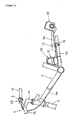
- Fig. 1 is a side view of a bicycle that incorporates a particular embodiment of a power supply circuit according to the present invention.
- the bicycle comprises a frame 1 including a double-loop frame body 2 and a front fork 3, a saddle 11, a handle unit 4, a drive unit 5, a front wheel 6 on which a brake-equipped dynamo hub 8 is mounted, a rear wheel 7 provided with a four-speed internal shifter hub 10, a shift controller 9 for the manual operation of the internal shifter hub 10, and a lamp control unit 18a.
- the handle unit 4 comprises a handle stem 14 fixed to the top portion of the front fork 3 and a handle bar 15 fixed to the handle stem 14.
- a brake lever 16 (Fig. 3) and a grip 17 are mounted on either end of the handle bar 15.
- the control panel 20 of the shift controller 9 is formed integrally with the right-side brake lever 16.
- the drive unit 5 comprises a gear crank 33 attached to the lower portion (bottom bracket) of the frame body 2, a chain 34 extending around the gear crank 33, and the internal shifter hub 10.
- the internal shifter hub 10 is a four-speed internal shifter hub that can be shifted into five positions (four shifting positions and one antitheft position) by a shifting motor 29, which is described below.
- the rotation of the rear wheel 7 can be restricted or blocked when internal shifter hub 10 is in the antitheft position.
- the dynamo hub 8 of the front wheel 6 fixed to the front end of the front fork 3 includes an externally mounted roller-type front brake and serves as an enclosure for an AC generator 19 (Fig. 5) for generating electricity by the rotation of the front wheel 6.
- the lamp control unit 18a is mounted in the midportion of the front fork 3.
- the lamp control unit 18a performs a control procedure whereby an integrally mounted lamp 18b is switched on when ambient luminosity falls beyond a prescribed level and is switched off when a certain brightness level is exceeded.
- the lamp control unit 18a is connected to the AC generator 19. As shown in Fig.
- the shift controller 9 comprises two control buttons 21 and 22 aligned to the right and left in the bottom portion of the control panel 20, a control dial 23 disposed above the control buttons 21 and 22, and a liquid-crystal display 24 disposed to the left of the control dial 23.
- the shift controller 9 communicates with a shift control unit 25 in a control box 31 (Fig. 2) mounted at the base of the chain stay 2a.
- the components housed in the control panel 20 are connected to the shift control unit 25 by a control cable 9a.
- a speed sensor 12 provided with an internal lead switch for speed sensing is mounted on the chain stay 2a of the frame body 2.
- the speed sensor 12 outputs a speed signal to shift controller 9 by sensing a magnet 13 mounted on a spoke 7a of the rear wheel 7.
- the control buttons 21 and 22 are triangular pushbuttons.
- the left-side control button 21 is a downshifting button, and the right-side control button 22 is an upshifting button.
- the shift modes comprise an automatic shift 1 (D) mode, an automatic shift 2 (Ds) mode, and a manual shift (M) mode.
- the automatic shift 1 (D) mode and automatic shift 2 (Ds) mode allow the internal shifter hub 10 to be automatically shifted by a speed signal from the speed sensor 12, whereas the manual shift mode (M) allows the internal shifter hub 10 to be shifted by operating the control buttons 21 and 22.
- the parking mode (P) is used to lock the internal shifter hub 10 and to prevent the rear wheel 7 from rotating.
- the liquid-crystal display 24 displays the current travel speed and the speed step engaged during shifting.
- the shift control unit 25 is provided with a microcomputer comprising a CPU, a RAM, a ROM, and an I/O interface.
- the shift control unit 25 controls the internal shifter hub 10 in accordance with the control operations performed with the control panel 20, as well as the information displayed by the liquid-crystal display 24.
- the control dial 23, the control buttons 21 and 22, the liquid-crystal display 24, and an alarm 32 are connected to the shift control unit 25.
- Also connected to the shift control unit 25 are, for example, an operating position sensor 26 composed of a potentiometer, a power supply 27 housed in the control box 31, a motor driver 28, a storage unit 30 for storing various types of data, and other input/output devices.
- a shifting motor 29 for driving the internal shifter hub 10 is connected to the motor driver 28, and the operating position sensor 26 senses the operating position (parking position or one of the four shifting positions) of the shifting motor 29.
- the power supply 27 is connected to the AC generator 19 in parallel with the lamp control unit 18a.
- the power supply 27 converts AC voltage to DC voltage, stores the result, and feeds the stored DC voltage to the shift controller 9.
- power supply 27 is housed in the control box 31.
- the power supply 27 has a case member 35 with an internal housing space and an external shape that conforms to the standard for commercially available batteries. An example is an oval shape capable of accommodating four AA batteries whose positive and negative poles are alternately oriented in opposite directions.
- control box 31 can accept either a conventional commercially available battery or a case member 31 according to the present invention. This allows emergency power to be supplied by a commercial battery during a breakdown or other emergency.
- the case member can also be mounted instead of a battery on an existing control box.
- the power supply 27 comprises a first input terminal 40, a second input terminal 41, a full-wave voltage rectifier circuit 42, a voltage regulator 43, a first output terminal 44, and a second output terminal 45.
- the first input terminal 40 is disposed on the external peripheral surface of the case member 35, and it is connected to the positive-voltage output terminal 19a of the AC generator 19.
- the second input terminal 41 is disposed on the external peripheral surface of the case member 35 in alignment with the first input terminal 40, and it is connected to the negative-voltage output terminal 19b of the AC generator 19.
- the first output terminal 44 is located on the case member 35 at a position normally occupied by the positive terminal on a commercially available battery case
- the second output terminal 45 is located on the case member 35 at a position normally occupied by the negative terminal on a commercially available battery case.
- the shift controller 9 is coupled as a load to the two output terminals 44 and 45.
- the full-wave voltage rectifier circuit 42 can store and output an AC voltage that is double the AC voltage presented by the two input terminals 40 and 41.
- the full-wave voltage rectifier circuit 42 comprises a first diode 50 whose anode terminal is coupled to the first input terminal 40; a second diode 51 whose cathode terminal is coupled to the first input terminal 40; a first storage element 52 in which one end is coupled to the cathode terminal of the first diode 50 and the other end is coupled to the second input terminal 41; and a second storage element 53 in which one end is coupled to the second input terminal 41 and the other end is coupled to the anode terminal of second diode 51.
- each of the two storage elements 52 and 53 features an electric double layer capacitor or other large-capacity capacitor and serves to store and smooth the DC voltage rectified by the diodes 50 and 51.
- the voltage regulator 43 is an output circuit for keeping the DC voltage produced by the full-wave voltage rectifier circuit 42 at a level not exceeding a first prescribed voltage (for example, 10 V), which is lower than the double voltage. This arrangement makes it possible to protect the storage elements 52 and 53 of the full-wave voltage rectifier circuit 42.
- the voltage regulator 43 comprises a first switch circuit 60 interposed between the first input terminal 40 and the first diode 50 and designed to make or break the connection between the two; a second switch circuit 61 interposed between the first input terminal 40 and the second diode 51 and designed to make or break the connection between the two; a third switch circuit 62 for switching on or off the DC voltage presented to the first and second output terminals 44 and 45; and a switch control circuit 63 for controlling the switch circuits 60-62.
- the three switch circuits 60-62 may, for example, feature field-effect transistors or other switching elements that are switched on or off by the control signals from the switch control circuit 63.
- Both ends of the switch control circuit 63 are coupled to the first and second output terminals 44 and 45, the voltage between the two output terminals 44 and 45 is sensed, and when the sensed voltage exceeds the first prescribed voltage, the first and second switch circuits 60 and 61 remain switched off for as long as the voltage is above the first prescribed voltage.
- the switch control circuit 63 switches off the third switch circuit 62 if the sensed voltage falls below a second prescribed voltage (for example, 4 V), which is lower than the first prescribed voltage.
- the AC generator 19 starts generating electricity when the bicycle is ridden and the front wheel 6 rotates.
- Current flows through the first diode 50 via the first switch circuit 60 during the positive half-periods of the input voltage applied from the output terminals 19a and 19b of the AC generator 19, thus charging the first storage element 52 to maximum positive AC voltage (e.g., +Vc).
- Current flows through the second diode 51 via the second switch circuit 61 during the negative half-periods of the input voltage applied from the output terminals 19a and 19b of the AC generator 19, thus charging the first storage element 52 to maximum negative AC voltage (e.g., -Vc).
- the voltage between the two output terminals 44 and 45 that is, the output voltage
- the output voltage becomes double the maximum supply voltage of the AC generator 19.
- the two switch circuits 60 and 61 are controlled by the switch control circuit 63 to produce a first prescribed voltage below the double supply voltage, so constant voltage less than double the supply voltage is produced.
- the third switch circuit 62 is switched off when the bicycle is ridden at a lower speed and the output voltage drops below the second prescribed voltage. This prevents power from being supplied to the shift controller 9 until the system is charged to a voltage equal to or greater than the second prescribed voltage.
- the foregoing arrangement allows sufficiently powerful voltage to be applied to the shift controller 9 even when the bicycle is ridden at a low speed because it is possible to deliver double the maximum voltage produced by the AC generator 19, and such voltage is stored in storage elements 51 and 52.
- the voltage thus delivered is kept constant by the switch control circuit 63, thus making it possible to provide the shift controller 9 with power whose voltage is stabilized even under variable speed conditions. Consequently, power can be delivered in a secure manner to electrical equipment based on microcomputers.
- the present invention is not limited by this shape alone and may, for example, include shapes resembling those of lithium batteries for cameras or those of other battery types or configurations such as AAA, A, B, C or D type batteries.
- the case member may also have a shape different from that of a battery and be mounted separately from the electrical equipment.
- the AC generator may also be provided as an integral component in the manner shown in Fig. 7. This arrangement dispenses with the need for the two input terminals, but third and fourth output terminals 44a and 45a for connecting the lamp control unit 18a and delivering an AC output are provided in addition to the first and second output terminals 44 and 45.
- the arrangement and number of these switch circuits are not limited to those adopted in the embodiment.
- the switch circuits can be disposed at positions indicated by the triangle, square, or circles in Fig. 8.
- the circles indicate the positioning of switch circuits between the storage elements 52 and 53 and the diodes 50 and 51 in accordance with a reverse arrangement relative to the above embodiment.
- the square and triangle indicate the positioning of switch circuits between the first input terminal 40 and the bifurcation point between the first input terminal 40 and the diodes 50 and 51, and between the second input terminal 41 at the bifurcation point between the storage elements 52 and 53.
- a single switch circuit e.g., square or triangle
- the lamp control unit 18a is arranged in parallel with the shift controller 9 rather than with the AC generator.
Landscapes
- Engineering & Computer Science (AREA)
- Mechanical Engineering (AREA)
- Charge And Discharge Circuits For Batteries Or The Like (AREA)
- Rectifiers (AREA)
- Control Of Charge By Means Of Generators (AREA)
- Control Of Eletrric Generators (AREA)
- Secondary Cells (AREA)
Applications Claiming Priority (2)
| Application Number | Priority Date | Filing Date | Title |
|---|---|---|---|
| JP2000053334 | 2000-02-29 | ||
| JP2000053334A JP3396655B2 (ja) | 2000-02-29 | 2000-02-29 | 自転車用電源装置 |
Publications (3)
| Publication Number | Publication Date |
|---|---|
| EP1129930A2 true EP1129930A2 (de) | 2001-09-05 |
| EP1129930A3 EP1129930A3 (de) | 2003-07-16 |
| EP1129930B1 EP1129930B1 (de) | 2009-05-27 |
Family
ID=18574733
Family Applications (1)
| Application Number | Title | Priority Date | Filing Date |
|---|---|---|---|
| EP01301580A Expired - Lifetime EP1129930B1 (de) | 2000-02-29 | 2001-02-22 | Stromversorgung für Fahrrad mit Spannungsregelkreis |
Country Status (7)
| Country | Link |
|---|---|
| US (1) | US6418041B1 (de) |
| EP (1) | EP1129930B1 (de) |
| JP (1) | JP3396655B2 (de) |
| CN (1) | CN1214516C (de) |
| AT (1) | ATE432209T1 (de) |
| DE (1) | DE60138778D1 (de) |
| TW (1) | TW553865B (de) |
Cited By (8)
| Publication number | Priority date | Publication date | Assignee | Title |
|---|---|---|---|---|
| EP1381069A2 (de) * | 2002-07-11 | 2004-01-14 | Shimano Inc. | Fahrradstromversorgung mit Vollwellen- und Halbwellen- Ladelementen |
| EP1394031A2 (de) * | 2002-08-30 | 2004-03-03 | Shimano Inc. | Apparat zum Verkabeln der Fahrradelektrik |
| EP1464569A2 (de) * | 2003-04-01 | 2004-10-06 | Shimano Inc. | Stromversorgung mit Entlade-Funktion für ein Fahrrad |
| EP1618625A2 (de) * | 2003-04-25 | 2006-01-25 | Maxwell Technologies, Inc. | Ladungsausgleichsschaltung für doppelschichtkondensatoren |
| EP1398266A3 (de) * | 2002-09-12 | 2006-05-17 | Shimano Inc. | Stromversorgung für Fahrrad |
| EP1465317A3 (de) * | 2003-04-01 | 2007-04-04 | Shimano Inc. | Fahrradstromversorgung mit verringertem Batterieleckstrom |
| TWI460092B (zh) * | 2010-04-28 | 2014-11-11 | 島野股份有限公司 | Bicycle electrical system |
| CN105128996A (zh) * | 2014-06-09 | 2015-12-09 | 株式会社岛野 | 电源供给系统、电动助力系统及电动变速系统 |
Families Citing this family (29)
| Publication number | Priority date | Publication date | Assignee | Title |
|---|---|---|---|---|
| JP2002187584A (ja) * | 2000-12-22 | 2002-07-02 | Shimano Inc | 自転車用電動ユニットの駆動制御回路 |
| JP2002262473A (ja) * | 2001-02-28 | 2002-09-13 | Shimano Inc | 自転車用充電制御回路 |
| JP3573723B2 (ja) * | 2001-06-29 | 2004-10-06 | 株式会社シマノ | 自転車用変速制御装置 |
| US6741045B2 (en) * | 2002-04-23 | 2004-05-25 | Shimano, Inc. | Bicycle control apparatus that communicates power and data over a single transmission path |
| JP3645881B2 (ja) * | 2002-10-18 | 2005-05-11 | 株式会社シマノ | 自転車用ダイナモの充電装置 |
| JP2004256047A (ja) * | 2003-02-27 | 2004-09-16 | Shimano Inc | 自転車用距離表示システム及び距離表示装置 |
| JP3752492B2 (ja) | 2003-03-28 | 2006-03-08 | 株式会社シマノ | 自転車用ハブ |
| US7321218B2 (en) * | 2003-05-19 | 2008-01-22 | Powell D. Nyachoto | Bicycle derailer generator |
| JP2005104258A (ja) * | 2003-09-30 | 2005-04-21 | Shimano Inc | 自転車用電装品ホルダー |
| JP3845092B2 (ja) * | 2004-01-16 | 2006-11-15 | 株式会社シマノ | 自転車用点灯装置 |
| JP2005225426A (ja) * | 2004-02-16 | 2005-08-25 | Shimano Inc | 自転車用照明装置及びそれに装着可能な自転車用表示装置。 |
| US7145256B2 (en) * | 2004-10-05 | 2006-12-05 | Alan William Koharcheck | Lighting system for a bicycle |
| JP4141453B2 (ja) * | 2005-03-16 | 2008-08-27 | 株式会社シマノ | 自転車用電源装置 |
| CN100391780C (zh) * | 2005-03-24 | 2008-06-04 | 洪宝川 | 自行车的电力供应装置 |
| JP2006325372A (ja) * | 2005-05-20 | 2006-11-30 | Shimano Inc | 人力駆動車用直流電源装置 |
| JP4326554B2 (ja) * | 2006-10-30 | 2009-09-09 | 株式会社シマノ | 自転車用照明装置 |
| USD598054S1 (en) | 2007-03-13 | 2009-08-11 | Nicholas Grimshaw | Combined information and advertising panel |
| USD608016S1 (en) | 2007-04-27 | 2010-01-12 | Nicholas Grimshaw | Booth assembly |
| US20080289890A1 (en) * | 2007-05-25 | 2008-11-27 | John Stoltzfus | Wheel-driven battery charger |
| US8132945B2 (en) * | 2007-10-09 | 2012-03-13 | Doug Lunde | Lighted bicycle pedal |
| US20100165608A1 (en) * | 2008-12-28 | 2010-07-01 | Hung-Chang Liu | Warning lamp with emergency power |
| US20100164334A1 (en) * | 2008-12-28 | 2010-07-01 | Jay Schiller | Bicycle with power generation and supply circuit |
| US20110080071A1 (en) * | 2009-10-06 | 2011-04-07 | Tzu-Wei Liu | Bicycle power supply module for supplying power to electrical devices on a bicycle and related bicycle |
| CN202179824U (zh) * | 2011-07-22 | 2012-04-04 | 北京美亚视景创恒科技有限公司 | 数字健身设备集群系统 |
| DE102012013890A1 (de) * | 2012-07-13 | 2014-01-16 | Audi Ag | Ladeeinrichtung für eine Hochspannungsbatterie eines Kraftfahrzeugs und Kraftfahrzeug |
| CN104022560A (zh) * | 2014-06-13 | 2014-09-03 | 东莞市卓和塑胶绳带有限公司 | 一种自行车骑行发电移动电源 |
| CN104515060A (zh) * | 2015-01-26 | 2015-04-15 | 李永红 | 一种自发电led摩托车及电动车灯 |
| JP6618184B2 (ja) * | 2015-03-19 | 2019-12-11 | AC Biode株式会社 | 高電圧発生装置 |
| GB2542117B (en) * | 2015-09-04 | 2022-04-06 | Smidsy Ltd | Laser projection device |
Citations (6)
| Publication number | Priority date | Publication date | Assignee | Title |
|---|---|---|---|---|
| US3991358A (en) * | 1973-11-28 | 1976-11-09 | Stanley Electric Co., Ltd. | Constant voltage device for a magneto alternating current generator |
| DE2818744A1 (de) * | 1978-04-28 | 1979-10-31 | Wiebe | Beleuchtungsanlage fuer fahrraeder |
| DE3911627A1 (de) * | 1988-04-11 | 1990-02-08 | Georg Froehlich | Beleuchtungsanlage fuer fahrraeder |
| US5247430A (en) * | 1990-06-07 | 1993-09-21 | Vereinigte Drahtwerke, A.G. | Light plant for bicycles including a dynamo |
| DE29815696U1 (de) * | 1998-09-01 | 1999-04-15 | Beier, Carsten, 08146 Ortmannsdorf | Leuchtmittel für Fahrradrücklicht |
| JPH11225446A (ja) * | 1998-02-05 | 1999-08-17 | Shindengen Electric Mfg Co Ltd | バッテリ充電装置 |
Family Cites Families (3)
| Publication number | Priority date | Publication date | Assignee | Title |
|---|---|---|---|---|
| US3792307A (en) * | 1972-07-26 | 1974-02-12 | D Baker | Bicycle safety lighting generator-battery system |
| US5015918A (en) * | 1988-07-22 | 1991-05-14 | John Copeland | Bicycle single-wire lighting system with steady-flashing-reflector rear warning device |
| US5661645A (en) * | 1996-06-27 | 1997-08-26 | Hochstein; Peter A. | Power supply for light emitting diode array |
-
2000
- 2000-02-29 JP JP2000053334A patent/JP3396655B2/ja not_active Expired - Fee Related
- 2000-10-25 TW TW089122454A patent/TW553865B/zh not_active IP Right Cessation
- 2000-11-22 US US09/722,089 patent/US6418041B1/en not_active Expired - Lifetime
-
2001
- 2001-01-02 CN CNB011013605A patent/CN1214516C/zh not_active Expired - Fee Related
- 2001-02-22 EP EP01301580A patent/EP1129930B1/de not_active Expired - Lifetime
- 2001-02-22 DE DE60138778T patent/DE60138778D1/de not_active Expired - Lifetime
- 2001-02-22 AT AT01301580T patent/ATE432209T1/de not_active IP Right Cessation
Patent Citations (6)
| Publication number | Priority date | Publication date | Assignee | Title |
|---|---|---|---|---|
| US3991358A (en) * | 1973-11-28 | 1976-11-09 | Stanley Electric Co., Ltd. | Constant voltage device for a magneto alternating current generator |
| DE2818744A1 (de) * | 1978-04-28 | 1979-10-31 | Wiebe | Beleuchtungsanlage fuer fahrraeder |
| DE3911627A1 (de) * | 1988-04-11 | 1990-02-08 | Georg Froehlich | Beleuchtungsanlage fuer fahrraeder |
| US5247430A (en) * | 1990-06-07 | 1993-09-21 | Vereinigte Drahtwerke, A.G. | Light plant for bicycles including a dynamo |
| JPH11225446A (ja) * | 1998-02-05 | 1999-08-17 | Shindengen Electric Mfg Co Ltd | バッテリ充電装置 |
| DE29815696U1 (de) * | 1998-09-01 | 1999-04-15 | Beier, Carsten, 08146 Ortmannsdorf | Leuchtmittel für Fahrradrücklicht |
Non-Patent Citations (1)
| Title |
|---|
| PATENT ABSTRACTS OF JAPAN vol. 1999, no. 13, 30 November 1999 (1999-11-30) & JP 11 225446 A (SHINDENGEN ELECTRIC MFG CO LTD), 17 August 1999 (1999-08-17) * |
Cited By (15)
| Publication number | Priority date | Publication date | Assignee | Title |
|---|---|---|---|---|
| EP1381069A2 (de) * | 2002-07-11 | 2004-01-14 | Shimano Inc. | Fahrradstromversorgung mit Vollwellen- und Halbwellen- Ladelementen |
| EP1381069A3 (de) * | 2002-07-11 | 2007-10-03 | Shimano Inc. | Fahrradstromversorgung mit Vollwellen- und Halbwellen- Ladelementen |
| EP1394031A3 (de) * | 2002-08-30 | 2006-09-06 | Shimano Inc. | Apparat zum Verkabeln der Fahrradelektrik |
| EP1394031A2 (de) * | 2002-08-30 | 2004-03-03 | Shimano Inc. | Apparat zum Verkabeln der Fahrradelektrik |
| EP1398266A3 (de) * | 2002-09-12 | 2006-05-17 | Shimano Inc. | Stromversorgung für Fahrrad |
| EP1464569A3 (de) * | 2003-04-01 | 2005-09-14 | Shimano Inc. | Stromversorgung mit Entlade-Funktion für ein Fahrrad |
| EP1464569A2 (de) * | 2003-04-01 | 2004-10-06 | Shimano Inc. | Stromversorgung mit Entlade-Funktion für ein Fahrrad |
| US7165641B2 (en) | 2003-04-01 | 2007-01-23 | Shimano, Inc. | Bicycle power supply with discharge function |
| EP1465317A3 (de) * | 2003-04-01 | 2007-04-04 | Shimano Inc. | Fahrradstromversorgung mit verringertem Batterieleckstrom |
| CN100352723C (zh) * | 2003-04-01 | 2007-12-05 | 株式会社岛野 | 自行车用电源装置 |
| EP1618625A2 (de) * | 2003-04-25 | 2006-01-25 | Maxwell Technologies, Inc. | Ladungsausgleichsschaltung für doppelschichtkondensatoren |
| EP1618625A4 (de) * | 2003-04-25 | 2007-10-03 | Maxwell Technologies Inc | Ladungsausgleichsschaltung für doppelschichtkondensatoren |
| TWI460092B (zh) * | 2010-04-28 | 2014-11-11 | 島野股份有限公司 | Bicycle electrical system |
| CN105128996A (zh) * | 2014-06-09 | 2015-12-09 | 株式会社岛野 | 电源供给系统、电动助力系统及电动变速系统 |
| CN105128996B (zh) * | 2014-06-09 | 2018-01-05 | 株式会社岛野 | 电源供给系统、电动助力系统及电动变速系统 |
Also Published As
| Publication number | Publication date |
|---|---|
| US6418041B1 (en) | 2002-07-09 |
| JP2001245475A (ja) | 2001-09-07 |
| JP3396655B2 (ja) | 2003-04-14 |
| TW553865B (en) | 2003-09-21 |
| EP1129930A3 (de) | 2003-07-16 |
| CN1311561A (zh) | 2001-09-05 |
| CN1214516C (zh) | 2005-08-10 |
| EP1129930B1 (de) | 2009-05-27 |
| ATE432209T1 (de) | 2009-06-15 |
| DE60138778D1 (de) | 2009-07-09 |
Similar Documents
| Publication | Publication Date | Title |
|---|---|---|
| US6418041B1 (en) | Bicycle power supply | |
| EP1464569B1 (de) | Stromversorgung mit Entlade-Funktion für ein Fahrrad | |
| EP1398266B1 (de) | Stromversorgung für Fahrrad | |
| US7410278B2 (en) | Bicycle light assembly with auxiliary output connector | |
| TW581738B (en) | Speed-changing control unit for bicycle | |
| US6835069B2 (en) | Apparatus for wiring bicycle electrical components | |
| US7045910B2 (en) | Bicycle power supply with reduced battery leakage | |
| US7119707B2 (en) | Circuit for providing electrical current to a bicycle device | |
| CN101295884A (zh) | 自行车电源和自行车电力系统 | |
| EP1424276B1 (de) | Elektronische Steuereinheit für ein Fahrrad | |
| EP2476575A1 (de) | Antriebssteuerung eines elektrisch motorisierten Motorrads |
Legal Events
| Date | Code | Title | Description |
|---|---|---|---|
| PUAI | Public reference made under article 153(3) epc to a published international application that has entered the european phase |
Free format text: ORIGINAL CODE: 0009012 |
|
| AK | Designated contracting states |
Kind code of ref document: A2 Designated state(s): AT BE CH CY DE DK ES FI FR GB GR IE IT LI LU MC NL PT SE TR |
|
| AX | Request for extension of the european patent |
Free format text: AL;LT;LV;MK;RO;SI |
|
| PUAL | Search report despatched |
Free format text: ORIGINAL CODE: 0009013 |
|
| AK | Designated contracting states |
Designated state(s): AT BE CH CY DE DK ES FI FR GB GR IE IT LI LU MC NL PT SE TR |
|
| AX | Request for extension of the european patent |
Extension state: AL LT LV MK RO SI |
|
| 17P | Request for examination filed |
Effective date: 20030804 |
|
| AKX | Designation fees paid |
Designated state(s): AT BE CH CY DE DK ES FI FR GB GR IE IT LI LU MC NL PT SE TR |
|
| RAP1 | Party data changed (applicant data changed or rights of an application transferred) |
Owner name: SHIMANO INC. |
|
| 17Q | First examination report despatched |
Effective date: 20061222 |
|
| RTI1 | Title (correction) |
Free format text: BICYCLE POWER SUPPLY WITH VOLTAGE CONTROL |
|
| GRAP | Despatch of communication of intention to grant a patent |
Free format text: ORIGINAL CODE: EPIDOSNIGR1 |
|
| GRAS | Grant fee paid |
Free format text: ORIGINAL CODE: EPIDOSNIGR3 |
|
| GRAA | (expected) grant |
Free format text: ORIGINAL CODE: 0009210 |
|
| AK | Designated contracting states |
Kind code of ref document: B1 Designated state(s): AT BE CH CY DE DK ES FI FR GB GR IE IT LI LU MC NL PT SE TR |
|
| REG | Reference to a national code |
Ref country code: GB Ref legal event code: FG4D |
|
| REG | Reference to a national code |
Ref country code: CH Ref legal event code: EP |
|
| REG | Reference to a national code |
Ref country code: IE Ref legal event code: FG4D |
|
| REF | Corresponds to: |
Ref document number: 60138778 Country of ref document: DE Date of ref document: 20090709 Kind code of ref document: P |
|
| PG25 | Lapsed in a contracting state [announced via postgrant information from national office to epo] |
Ref country code: FI Free format text: LAPSE BECAUSE OF FAILURE TO SUBMIT A TRANSLATION OF THE DESCRIPTION OR TO PAY THE FEE WITHIN THE PRESCRIBED TIME-LIMIT Effective date: 20090527 Ref country code: AT Free format text: LAPSE BECAUSE OF FAILURE TO SUBMIT A TRANSLATION OF THE DESCRIPTION OR TO PAY THE FEE WITHIN THE PRESCRIBED TIME-LIMIT Effective date: 20090527 Ref country code: PT Free format text: LAPSE BECAUSE OF FAILURE TO SUBMIT A TRANSLATION OF THE DESCRIPTION OR TO PAY THE FEE WITHIN THE PRESCRIBED TIME-LIMIT Effective date: 20090927 |
|
| NLV1 | Nl: lapsed or annulled due to failure to fulfill the requirements of art. 29p and 29m of the patents act | ||
| PG25 | Lapsed in a contracting state [announced via postgrant information from national office to epo] |
Ref country code: SE Free format text: LAPSE BECAUSE OF FAILURE TO SUBMIT A TRANSLATION OF THE DESCRIPTION OR TO PAY THE FEE WITHIN THE PRESCRIBED TIME-LIMIT Effective date: 20090827 Ref country code: NL Free format text: LAPSE BECAUSE OF FAILURE TO SUBMIT A TRANSLATION OF THE DESCRIPTION OR TO PAY THE FEE WITHIN THE PRESCRIBED TIME-LIMIT Effective date: 20090527 |
|
| PG25 | Lapsed in a contracting state [announced via postgrant information from national office to epo] |
Ref country code: ES Free format text: LAPSE BECAUSE OF FAILURE TO SUBMIT A TRANSLATION OF THE DESCRIPTION OR TO PAY THE FEE WITHIN THE PRESCRIBED TIME-LIMIT Effective date: 20090907 Ref country code: DK Free format text: LAPSE BECAUSE OF FAILURE TO SUBMIT A TRANSLATION OF THE DESCRIPTION OR TO PAY THE FEE WITHIN THE PRESCRIBED TIME-LIMIT Effective date: 20090527 |
|
| PG25 | Lapsed in a contracting state [announced via postgrant information from national office to epo] |
Ref country code: BE Free format text: LAPSE BECAUSE OF FAILURE TO SUBMIT A TRANSLATION OF THE DESCRIPTION OR TO PAY THE FEE WITHIN THE PRESCRIBED TIME-LIMIT Effective date: 20090527 |
|
| PLBE | No opposition filed within time limit |
Free format text: ORIGINAL CODE: 0009261 |
|
| STAA | Information on the status of an ep patent application or granted ep patent |
Free format text: STATUS: NO OPPOSITION FILED WITHIN TIME LIMIT |
|
| 26N | No opposition filed |
Effective date: 20100302 |
|
| REG | Reference to a national code |
Ref country code: CH Ref legal event code: PL |
|
| GBPC | Gb: european patent ceased through non-payment of renewal fee |
Effective date: 20100222 |
|
| PG25 | Lapsed in a contracting state [announced via postgrant information from national office to epo] |
Ref country code: MC Free format text: LAPSE BECAUSE OF NON-PAYMENT OF DUE FEES Effective date: 20100301 Ref country code: CH Free format text: LAPSE BECAUSE OF NON-PAYMENT OF DUE FEES Effective date: 20100228 Ref country code: GR Free format text: LAPSE BECAUSE OF FAILURE TO SUBMIT A TRANSLATION OF THE DESCRIPTION OR TO PAY THE FEE WITHIN THE PRESCRIBED TIME-LIMIT Effective date: 20090828 Ref country code: LI Free format text: LAPSE BECAUSE OF NON-PAYMENT OF DUE FEES Effective date: 20100228 |
|
| REG | Reference to a national code |
Ref country code: FR Ref legal event code: ST Effective date: 20101029 |
|
| PG25 | Lapsed in a contracting state [announced via postgrant information from national office to epo] |
Ref country code: FR Free format text: LAPSE BECAUSE OF NON-PAYMENT OF DUE FEES Effective date: 20100301 Ref country code: IE Free format text: LAPSE BECAUSE OF NON-PAYMENT OF DUE FEES Effective date: 20100222 |
|
| PG25 | Lapsed in a contracting state [announced via postgrant information from national office to epo] |
Ref country code: GB Free format text: LAPSE BECAUSE OF NON-PAYMENT OF DUE FEES Effective date: 20100222 |
|
| PG25 | Lapsed in a contracting state [announced via postgrant information from national office to epo] |
Ref country code: CY Free format text: LAPSE BECAUSE OF FAILURE TO SUBMIT A TRANSLATION OF THE DESCRIPTION OR TO PAY THE FEE WITHIN THE PRESCRIBED TIME-LIMIT Effective date: 20090527 |
|
| PG25 | Lapsed in a contracting state [announced via postgrant information from national office to epo] |
Ref country code: LU Free format text: LAPSE BECAUSE OF NON-PAYMENT OF DUE FEES Effective date: 20100222 |
|
| PG25 | Lapsed in a contracting state [announced via postgrant information from national office to epo] |
Ref country code: TR Free format text: LAPSE BECAUSE OF FAILURE TO SUBMIT A TRANSLATION OF THE DESCRIPTION OR TO PAY THE FEE WITHIN THE PRESCRIBED TIME-LIMIT Effective date: 20090527 |
|
| PGFP | Annual fee paid to national office [announced via postgrant information from national office to epo] |
Ref country code: IT Payment date: 20140218 Year of fee payment: 14 |
|
| PG25 | Lapsed in a contracting state [announced via postgrant information from national office to epo] |
Ref country code: IT Free format text: LAPSE BECAUSE OF NON-PAYMENT OF DUE FEES Effective date: 20150222 |
|
| PGFP | Annual fee paid to national office [announced via postgrant information from national office to epo] |
Ref country code: DE Payment date: 20170214 Year of fee payment: 17 |
|
| REG | Reference to a national code |
Ref country code: DE Ref legal event code: R119 Ref document number: 60138778 Country of ref document: DE |
|
| PG25 | Lapsed in a contracting state [announced via postgrant information from national office to epo] |
Ref country code: DE Free format text: LAPSE BECAUSE OF NON-PAYMENT OF DUE FEES Effective date: 20180901 |