EP1129918B1 - Hydraulische Pumpeneinheit für ein Fahrzeug - Google Patents
Hydraulische Pumpeneinheit für ein Fahrzeug Download PDFInfo
- Publication number
- EP1129918B1 EP1129918B1 EP00830165A EP00830165A EP1129918B1 EP 1129918 B1 EP1129918 B1 EP 1129918B1 EP 00830165 A EP00830165 A EP 00830165A EP 00830165 A EP00830165 A EP 00830165A EP 1129918 B1 EP1129918 B1 EP 1129918B1
- Authority
- EP
- European Patent Office
- Prior art keywords
- pump unit
- reservoir
- bleed
- nipple
- circuit
- Prior art date
- Legal status (The legal status is an assumption and is not a legal conclusion. Google has not performed a legal analysis and makes no representation as to the accuracy of the status listed.)
- Expired - Lifetime
Links
- 210000002445 nipple Anatomy 0.000 claims abstract description 36
- 239000012530 fluid Substances 0.000 claims abstract description 25
- 238000007373 indentation Methods 0.000 claims description 7
- 230000000740 bleeding effect Effects 0.000 abstract description 8
- 230000003749 cleanliness Effects 0.000 description 3
- 238000011109 contamination Methods 0.000 description 2
- 239000000463 material Substances 0.000 description 2
- 230000006978 adaptation Effects 0.000 description 1
- 239000007789 gas Substances 0.000 description 1
- 238000000034 method Methods 0.000 description 1
- 238000012986 modification Methods 0.000 description 1
- 230000004048 modification Effects 0.000 description 1
- 238000006467 substitution reaction Methods 0.000 description 1
- 230000000007 visual effect Effects 0.000 description 1
Images


Classifications
-
- F—MECHANICAL ENGINEERING; LIGHTING; HEATING; WEAPONS; BLASTING
- F15—FLUID-PRESSURE ACTUATORS; HYDRAULICS OR PNEUMATICS IN GENERAL
- F15B—SYSTEMS ACTING BY MEANS OF FLUIDS IN GENERAL; FLUID-PRESSURE ACTUATORS, e.g. SERVOMOTORS; DETAILS OF FLUID-PRESSURE SYSTEMS, NOT OTHERWISE PROVIDED FOR
- F15B21/00—Common features of fluid actuator systems; Fluid-pressure actuator systems or details thereof, not covered by any other group of this subclass
- F15B21/04—Special measures taken in connection with the properties of the fluid
- F15B21/044—Removal or measurement of undissolved gas, e.g. de-aeration, venting or bleeding
-
- B—PERFORMING OPERATIONS; TRANSPORTING
- B60—VEHICLES IN GENERAL
- B60T—VEHICLE BRAKE CONTROL SYSTEMS OR PARTS THEREOF; BRAKE CONTROL SYSTEMS OR PARTS THEREOF, IN GENERAL; ARRANGEMENT OF BRAKING ELEMENTS ON VEHICLES IN GENERAL; PORTABLE DEVICES FOR PREVENTING UNWANTED MOVEMENT OF VEHICLES; VEHICLE MODIFICATIONS TO FACILITATE COOLING OF BRAKES
- B60T11/00—Transmitting braking action from initiating means to ultimate brake actuator without power assistance or drive or where such assistance or drive is irrelevant
- B60T11/10—Transmitting braking action from initiating means to ultimate brake actuator without power assistance or drive or where such assistance or drive is irrelevant transmitting by fluid means, e.g. hydraulic
- B60T11/28—Valves specially adapted therefor
- B60T11/30—Bleed valves for hydraulic brake systems
Definitions
- the subject of the present invention is a hydraulic pump unit for a vehicle in accordance with the preamble of Claim 1.
- a pump unit is known from prior art FR-A-2 538 765 .
- the present invention relates in particular to a pump unit for vehicle brakes and/or clutches.
- both the actuators the calipers and their cylinders
- the pump units for the brake or clutch include a bleed circuit via which any air present in the circuit can be removed.
- brake fluid denotes a fluid suitable for operating pump units for brakes and/or clutches of vehicles.
- a pump unit can be produced in which the bleed circuit leads from the master cylinder of the pump to the exterior and is fitted with a bleed nipple, onto which the end of a length of tube can be pushed while its other end is submerged in a container to collect the discharged brake fluid.
- the circuit is pressurized by operating the pump and then opening the bleed nipple to draw off a small amount of brake fluid and the air bubbles present within it.
- the bleed nipple is then re-tightened before the pump control is released.
- This known pump unit is not without certain disadvantages.
- the bleed tubing and the container for collecting the discharged brake fluid have to be connected up to, and then disconnected from, the bleed circuit.
- the tubing and the container have to be made from materials compatible with the brake fluid, which is highly corrosive towards many materials.
- the brake fluid should not be able to damage the paintwork of the vehicle, against which it is particularly corrosive.
- the technical problem addressed by this invention is that of providing a pump unit, designed particularly but not exclusively for motorcycle applications, that is structurally and functionally such as to overcome all the disadvantages discussed with reference to the prior art cited above.
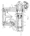
- the number 1 is an overall indication for a hydraulic pump unit for a vehicle, for instance a hydraulic brake pump unit for use on two-wheeled vehicles, motor cycles, snowmobiles and vehicles controlled via handlebars, or such like vehicles.
- the unit 1 comprises a reservoir 2 containing the brake fluid and equipped with a pump having a master cylinder 3 in which a floating piston 4, with a seal 5, slides leaktightly in an axial direction.
- the piston is pushed elastically towards a position of release or relaxation (shown in Figure 1 ) by a spring 12 acting between it and a shoulder 13 in the master cylinder 3.
- the reservoir 2 communicates with the master cylinder 3 through passages 6, 7 and is closed at its mouth 8 by a cover 9 that is fastened removably with screws 10.
- a gasket 11 is provided between the mouth 8 of the reservoir and the cover 9.
- a bleed circuit with the general indication 15 runs between the master cylinder 3 and the reservoir 2.
- the bleed circuit comprises a first length 16a which is cylindrical, has an approximately constant diameter, opens into the master cylinder in the vicinity of the shoulder 13 and ends in the opposite direction in a seating 17 for a frustoconical shutoff member 18 produced on an axial end of a bleed nipple 19.
- the nipple 19 can be screwed in and out in a threaded second length 16b of the bleed circuit 15, contains an axial cavity 20 that divides up into first and second radial passages 21, 22, and has a head 23 containing a hexagonal sunken indentation 24 for turning by means of a key.
- the axial cavity 20 opens directly into the reservoir, whereas in the nipple 219 it is closed off and discharge into the reservoir is via the radial passage 22.
- the bleed circuit 15 opens into the reservoir 2 at a substantially lower level than the normal operating level (L) of the brake fluid contained in the reservoir so that the outlet of the circuit 15 is always submerged, during bleeding operations, in the aforementioned brake fluid.
- the bleed nipple is accessible through the reservoir, and that the outlet of the circuit into the reservoir preferably does not point directly towards the mouth (or cover) in order to avoid brake fluid being ejected out of the reservoir during bleeding operations.
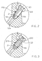
- FIGS 4 and 5 illustrate a second example of an embodiment of the invention in two variants indicated by the respective general references 301 and 401. Details analogous to those of the earlier figures are indicated by the same reference numerals.
- the bleed nipple 319, 419 in both variants of this example is not accessible through the reservoir 2 but through a hole 30 formed in the thickness of one of the walls 31 of the reservoir 2 and parallel to this wall.
- the hole 30 coincides with the hole for one of the screws 10 used to secure the cover 9 and the bleed nipple 319 is accessible following removal of this screw but without the cover 9 having to be removed.
- the hole 30 is formed with an axis parallel to and spaced apart from the fixing screws 10 and is closed removably by the cover 9. In the latter case access to the bleed nipple requires that the cover 9 be taken off first.
- the bleed nipple 223, 319, 419 is structurally similar to that of the example of Figure 1 , from which it differs however in that the axial cavity 20 is closed by a ball 33 forced into the end of the hexagonal sunken indentation 24, thus ensuring that the fluid escapes through the first and second radial passages or diametrical holes.
- the bleed nipple 319, 419 is also differentiated by the fact that an O-ring 32 is provided between it and the hole 30 to prevent leakage out of the reservoir 2 along the bleed nipple. This serves to further prevent the risk of contamination of the brake fluid present in the reservoir.
- the bleed nipple is slackened off so that some of the brake fluid escapes through the bleed circuit into the reservoir, carrying any air bubbles with it in the process. Even if the cover 9 of the reservoir has been removed, as it must be in all the examples illustrated with the exception of that of Figure 4 , no brake fluid will be ejected out of the reservoir because the small pressurized jet of fluid at the outlet of the bleed channel is not directed towards the mouth 8.
Landscapes
- Engineering & Computer Science (AREA)
- Mechanical Engineering (AREA)
- Chemical & Material Sciences (AREA)
- Analytical Chemistry (AREA)
- Physics & Mathematics (AREA)
- Fluid Mechanics (AREA)
- General Engineering & Computer Science (AREA)
- Transportation (AREA)
- Valves And Accessory Devices For Braking Systems (AREA)
- Transmission Of Braking Force In Braking Systems (AREA)
- Fluid-Pressure Circuits (AREA)
- Braking Systems And Boosters (AREA)
Claims (13)
- Hydraulikpumpeneinheit (1) für eine Bremse oder eine Kupplung eines Fahrzeugs, umfassend einen Reservoir (2) für die Flüssigkeit, einen mit dem Reservoir verbundenen Hauptzylinder (3) in der Pumpe und einen Ableitkreislauf (15), welcher an einem Ende mit dem Hauptzylinder verbunden ist und mit einem Ableitstutzen (19, 119, 219, 319, 419) ausgestattet ist, welcher normalerweise geschlossen ist, um den Kreislauf abzuschließen, wobei der Ableitkreislauf (15) an dem anderen Ende stromabwärts des Ableitstutzens (19, 119, 219, 319, 419) mit dem Reservoir (2) verbunden ist, dadurch gekennzeichnet, dass der Ableitstutzen (19, 119, 219) durch das Reservoir zugänglich ist, und dadurch, dass das Reservoir und der Hauptzylinder in einem Stück gebildet sind.
- Pumpeneinheit (1) nach Anspruch 1, wobei der Ableitkreislauf (15) auf einem wesentlich geringeren Niveau in das Reservoir (2) hinein offen ist als das normale Betriebsniveau (L) der Bremsflüssigkeit in dem Reservoir.
- Pumpeneinheit (1) nach Anspruch 1 oder 2, wobei das Reservoir (2) mit einer Mündung (8) versehen ist, welche entfernbar durch eine Abdeckung (9) verschlossen ist, wobei der Kreislauf mit einem Auslass in das Reservoir versehen ist, der nicht direkt zu der Mündung zeigt.
- Pumpeneinheit (1) nach Anspruch 3, bei welcher der Ableitstutzen (19, 119, 219, 319, 419) einen Schaft aufweist, der einen axialen Hohlraum (20) enthält, und wobei der Auslass von dem axialen Hohlraum radial durch den Ableitstutzen führt.
- Pumpeneinheit (1) nach Anspruch 4, wobei der Ableitstutzen (19, 319, 419) einen dem Schaft zugeordneten Kopf (23) aufweist, welcher eine Einkerbung (24) für einen Schlüssel aufweist.
- Pumpeneinheit (1) nach Anspruch 5, wobei die Einkerbung (24) für einen Schlüssel ein vertieftes Sechseck ist.
- Hydraulikpumpeneinheit (1) nach einem der vorangehenden Ansprüche, wobei der Ableitstutzen (319, 419) durch ein in einer der Wände (31) des Reservoirs (2) und parallel dazu gebildetes Loch (30) zugänglich ist.
- Pumpeneinheit (1) nach Anspruch 7, wobei das Loch (30) entfernbar durch eine Schraube (10) verschlossen ist, welche als Befestigungsschraube für die Abdeckung dient.
- Pumpeneinheit (1) nach einem oder mehreren der Ansprüche 7 bis 8, wobei der Ableitstutzen (19, 219, 319, 419) einen Schaft aufweist, welcher einen axialen Hohlraum (20) enthält, und wobei der Auslass von dem axialen Hohlraum radial durch den Ableitstutzen führt.
- Pumpeneinheit (1) nach Anspruch 9, wobei der Ableitstutzen (19, 319, 419) einen dem Schaft zugeordneten Kopf (23) aufweist, welcher eine Einkerbung (24) für einen Schlüssel aufweist.
- Pumpeneinheit (1) nach Anspruch 10, wobei die Einkerbung (24) für einen Schlüssel ein vertieftes Sechseck ist.
- Fahrzeugbremsensystem, umfassend eine Pumpeneinheit (1) gemäß jedem der vorangehenden Ansprüche.
- System zum Betreiben einer Fahrzeugreibungskupplung, umfassend eine Pumpeneinheit (1) gemäß jedem der Ansprüche 1 bis 11.
Priority Applications (8)
| Application Number | Priority Date | Filing Date | Title |
|---|---|---|---|
| ES00830165T ES2306651T3 (es) | 2000-03-03 | 2000-03-03 | Unidad de bomba hidraulica para vehiculo. |
| AT00830165T ATE395228T1 (de) | 2000-03-03 | 2000-03-03 | Hydraulische pumpeneinheit für ein fahrzeug |
| DE60038865T DE60038865D1 (de) | 2000-03-03 | 2000-03-03 | Hydraulische Pumpeneinheit für ein Fahrzeug |
| EP00830165A EP1129918B1 (de) | 2000-03-03 | 2000-03-03 | Hydraulische Pumpeneinheit für ein Fahrzeug |
| PCT/EP2001/001180 WO2001064491A1 (en) | 2000-03-03 | 2001-02-05 | Hydraulic master cylinder for vehicle |
| JP2001563362A JP4880165B2 (ja) | 2000-03-03 | 2001-02-05 | 車両のための油圧マスターシリンダー |
| US10/220,867 US6892536B2 (en) | 2000-03-03 | 2001-02-05 | Hydraulic pump unit for vehicle |
| AU2001240583A AU2001240583A1 (en) | 2000-03-03 | 2001-02-05 | Hydraulic master cylinder for vehicle |
Applications Claiming Priority (1)
| Application Number | Priority Date | Filing Date | Title |
|---|---|---|---|
| EP00830165A EP1129918B1 (de) | 2000-03-03 | 2000-03-03 | Hydraulische Pumpeneinheit für ein Fahrzeug |
Publications (2)
| Publication Number | Publication Date |
|---|---|
| EP1129918A1 EP1129918A1 (de) | 2001-09-05 |
| EP1129918B1 true EP1129918B1 (de) | 2008-05-14 |
Family
ID=8175224
Family Applications (1)
| Application Number | Title | Priority Date | Filing Date |
|---|---|---|---|
| EP00830165A Expired - Lifetime EP1129918B1 (de) | 2000-03-03 | 2000-03-03 | Hydraulische Pumpeneinheit für ein Fahrzeug |
Country Status (8)
| Country | Link |
|---|---|
| US (1) | US6892536B2 (de) |
| EP (1) | EP1129918B1 (de) |
| JP (1) | JP4880165B2 (de) |
| AT (1) | ATE395228T1 (de) |
| AU (1) | AU2001240583A1 (de) |
| DE (1) | DE60038865D1 (de) |
| ES (1) | ES2306651T3 (de) |
| WO (1) | WO2001064491A1 (de) |
Cited By (1)
| Publication number | Priority date | Publication date | Assignee | Title |
|---|---|---|---|---|
| CN107956823A (zh) * | 2016-10-17 | 2018-04-24 | 坎培诺洛有限公司 | 用于自行车液压刹车系统的排气阀 |
Families Citing this family (3)
| Publication number | Priority date | Publication date | Assignee | Title |
|---|---|---|---|---|
| EP1501713A1 (de) * | 2002-04-30 | 2005-02-02 | Freni Brembo S.p.A. | Hauptbremszylindereinheit für fahrzeuge |
| US10457265B2 (en) * | 2017-03-09 | 2019-10-29 | Ford Global Technologies, Llc | Methods and apparatus to facilitate brake bleeding |
| DE102021128118B3 (de) * | 2021-10-28 | 2022-11-24 | FAHRWERKER GmbH | Hydraulikarmatur |
Family Cites Families (11)
| Publication number | Priority date | Publication date | Assignee | Title |
|---|---|---|---|---|
| US2524544A (en) * | 1948-03-02 | 1950-10-03 | Harry T Seawell | Hydraulic brake bleeder system |
| US3247670A (en) * | 1964-03-23 | 1966-04-26 | Gen Motors Corp | Master cylinder with in-line compensating valve |
| US3559405A (en) * | 1969-03-20 | 1971-02-02 | Roger L Neilson | Self-bleeding, self-circulating braking system |
| FR2538765B1 (fr) * | 1982-12-30 | 1986-08-01 | Peugeot | Dispositif hydraulique pour la commande du freinage ou de l'embrayage d'un vehicule automobile |
| JPS61111868A (ja) * | 1984-11-06 | 1986-05-29 | Olympus Optical Co Ltd | 微小送り装置 |
| JPS61111868U (de) * | 1984-12-27 | 1986-07-15 | ||
| JPS62189997A (ja) * | 1986-02-12 | 1987-08-19 | Fuji Electric Co Ltd | 発電機の同期投入制御装置 |
| JPH0355515Y2 (de) * | 1986-05-26 | 1991-12-10 | ||
| US4971402A (en) * | 1989-09-12 | 1990-11-20 | Chen Teh Chih | Vehicle brake system with locking preventive mechanism |
| US5040816A (en) * | 1990-06-04 | 1991-08-20 | Unique Functional Products | Actuator/coupler |
| JPH09207752A (ja) * | 1996-02-07 | 1997-08-12 | Nissin Kogyo Kk | 車両用液圧マスタシリンダ |
-
2000
- 2000-03-03 EP EP00830165A patent/EP1129918B1/de not_active Expired - Lifetime
- 2000-03-03 AT AT00830165T patent/ATE395228T1/de not_active IP Right Cessation
- 2000-03-03 ES ES00830165T patent/ES2306651T3/es not_active Expired - Lifetime
- 2000-03-03 DE DE60038865T patent/DE60038865D1/de not_active Expired - Lifetime
-
2001
- 2001-02-05 US US10/220,867 patent/US6892536B2/en not_active Expired - Fee Related
- 2001-02-05 AU AU2001240583A patent/AU2001240583A1/en not_active Abandoned
- 2001-02-05 WO PCT/EP2001/001180 patent/WO2001064491A1/en not_active Ceased
- 2001-02-05 JP JP2001563362A patent/JP4880165B2/ja not_active Expired - Fee Related
Cited By (2)
| Publication number | Priority date | Publication date | Assignee | Title |
|---|---|---|---|---|
| CN107956823A (zh) * | 2016-10-17 | 2018-04-24 | 坎培诺洛有限公司 | 用于自行车液压刹车系统的排气阀 |
| CN107956823B (zh) * | 2016-10-17 | 2020-12-15 | 坎培诺洛有限公司 | 用于自行车液压刹车系统的排气阀 |
Also Published As
| Publication number | Publication date |
|---|---|
| JP4880165B2 (ja) | 2012-02-22 |
| AU2001240583A1 (en) | 2001-09-12 |
| JP2003525168A (ja) | 2003-08-26 |
| EP1129918A1 (de) | 2001-09-05 |
| DE60038865D1 (de) | 2008-06-26 |
| ATE395228T1 (de) | 2008-05-15 |
| ES2306651T3 (es) | 2008-11-16 |
| US6892536B2 (en) | 2005-05-17 |
| US20030159440A1 (en) | 2003-08-28 |
| WO2001064491A1 (en) | 2001-09-07 |
Similar Documents
| Publication | Publication Date | Title |
|---|---|---|
| EP1129918B1 (de) | Hydraulische Pumpeneinheit für ein Fahrzeug | |
| US4834140A (en) | Brake bleeder valve | |
| EP1798126B1 (de) | Entlüftungsschraube für Fahrradbremsanlage | |
| US4989639A (en) | Brake bleeder check valve | |
| GB2257216A (en) | Hydraulic braking systems | |
| WO2000040445A1 (en) | Brake bleeder check valve | |
| JP3970961B2 (ja) | 機能停止安全形の液圧逃し/ダンプ弁 | |
| US6250447B1 (en) | Hydraulic operating system, particularly for a motorcycle brake and/or clutch | |
| US3298471A (en) | Valve for hydraulic brake holding system | |
| US20090212249A1 (en) | Bleeding Screw Having a Kick-Back Valve | |
| US4474272A (en) | Hydraulic brake cylinder fluid supply and bleeding mechanism | |
| US3318330A (en) | Tool for bleeding hydraulic brakes | |
| CA1305643C (en) | Brake bleeder valve | |
| US20040074722A1 (en) | Method for filling hydraulic apparatus with liquid, and apparatus thus filled | |
| GR3004822T3 (de) | ||
| KR100337316B1 (ko) | 에이비에스 장착 차량의 에어 블리딩 장치 | |
| KR200158183Y1 (ko) | 에어 브리딩 장치 | |
| WO1999038744A1 (en) | Submersible brake actuator | |
| JP3056403U (ja) | 自動車のブレーキ油圧装置 | |
| KR0125123Y1 (ko) | 차량의 제동력 유지장치 | |
| KR970064989A (ko) | 타이어의 공기압 자동보충장치 | |
| KR100535456B1 (ko) | 오일 팬의 오일 드레인 장치 | |
| KR101297567B1 (ko) | 마스터 실린더 | |
| KR19980023595U (ko) | 차량용 마스터실린더의 에어 브리딩구조 | |
| JP2005523840A (ja) | 車輌用マスターシリンダー装置 |
Legal Events
| Date | Code | Title | Description |
|---|---|---|---|
| PUAI | Public reference made under article 153(3) epc to a published international application that has entered the european phase |
Free format text: ORIGINAL CODE: 0009012 |
|
| AK | Designated contracting states |
Kind code of ref document: A1 Designated state(s): AT BE CH CY DE DK ES FI FR GB GR IE IT LI LU MC NL PT SE |
|
| AX | Request for extension of the european patent |
Free format text: AL;LT;LV;MK;RO;SI |
|
| 17P | Request for examination filed |
Effective date: 20020218 |
|
| AKX | Designation fees paid |
Free format text: AT BE CH CY DE DK ES FI FR GB GR IE IT LI LU MC NL PT SE |
|
| 17Q | First examination report despatched |
Effective date: 20050602 |
|
| GRAP | Despatch of communication of intention to grant a patent |
Free format text: ORIGINAL CODE: EPIDOSNIGR1 |
|
| GRAS | Grant fee paid |
Free format text: ORIGINAL CODE: EPIDOSNIGR3 |
|
| GRAA | (expected) grant |
Free format text: ORIGINAL CODE: 0009210 |
|
| AK | Designated contracting states |
Kind code of ref document: B1 Designated state(s): AT BE CH CY DE DK ES FI FR GB GR IE IT LI LU MC NL PT SE |
|
| REG | Reference to a national code |
Ref country code: GB Ref legal event code: FG4D |
|
| REG | Reference to a national code |
Ref country code: CH Ref legal event code: EP |
|
| REG | Reference to a national code |
Ref country code: IE Ref legal event code: FG4D Free format text: LANGUAGE OF EP DOCUMENT: FRENCH |
|
| REF | Corresponds to: |
Ref document number: 60038865 Country of ref document: DE Date of ref document: 20080626 Kind code of ref document: P |
|
| PG25 | Lapsed in a contracting state [announced via postgrant information from national office to epo] |
Ref country code: FI Free format text: LAPSE BECAUSE OF FAILURE TO SUBMIT A TRANSLATION OF THE DESCRIPTION OR TO PAY THE FEE WITHIN THE PRESCRIBED TIME-LIMIT Effective date: 20080514 |
|
| NLV1 | Nl: lapsed or annulled due to failure to fulfill the requirements of art. 29p and 29m of the patents act | ||
| REG | Reference to a national code |
Ref country code: ES Ref legal event code: FG2A Ref document number: 2306651 Country of ref document: ES Kind code of ref document: T3 |
|
| PG25 | Lapsed in a contracting state [announced via postgrant information from national office to epo] |
Ref country code: NL Free format text: LAPSE BECAUSE OF FAILURE TO SUBMIT A TRANSLATION OF THE DESCRIPTION OR TO PAY THE FEE WITHIN THE PRESCRIBED TIME-LIMIT Effective date: 20080514 Ref country code: AT Free format text: LAPSE BECAUSE OF FAILURE TO SUBMIT A TRANSLATION OF THE DESCRIPTION OR TO PAY THE FEE WITHIN THE PRESCRIBED TIME-LIMIT Effective date: 20080514 |
|
| PG25 | Lapsed in a contracting state [announced via postgrant information from national office to epo] |
Ref country code: SE Free format text: LAPSE BECAUSE OF FAILURE TO SUBMIT A TRANSLATION OF THE DESCRIPTION OR TO PAY THE FEE WITHIN THE PRESCRIBED TIME-LIMIT Effective date: 20080814 Ref country code: DK Free format text: LAPSE BECAUSE OF FAILURE TO SUBMIT A TRANSLATION OF THE DESCRIPTION OR TO PAY THE FEE WITHIN THE PRESCRIBED TIME-LIMIT Effective date: 20080514 Ref country code: PT Free format text: LAPSE BECAUSE OF FAILURE TO SUBMIT A TRANSLATION OF THE DESCRIPTION OR TO PAY THE FEE WITHIN THE PRESCRIBED TIME-LIMIT Effective date: 20081014 |
|
| PG25 | Lapsed in a contracting state [announced via postgrant information from national office to epo] |
Ref country code: BE Free format text: LAPSE BECAUSE OF FAILURE TO SUBMIT A TRANSLATION OF THE DESCRIPTION OR TO PAY THE FEE WITHIN THE PRESCRIBED TIME-LIMIT Effective date: 20080514 |
|
| PLBE | No opposition filed within time limit |
Free format text: ORIGINAL CODE: 0009261 |
|
| STAA | Information on the status of an ep patent application or granted ep patent |
Free format text: STATUS: NO OPPOSITION FILED WITHIN TIME LIMIT |
|
| 26N | No opposition filed |
Effective date: 20090217 |
|
| PG25 | Lapsed in a contracting state [announced via postgrant information from national office to epo] |
Ref country code: MC Free format text: LAPSE BECAUSE OF NON-PAYMENT OF DUE FEES Effective date: 20090331 |
|
| REG | Reference to a national code |
Ref country code: CH Ref legal event code: PL |
|
| REG | Reference to a national code |
Ref country code: FR Ref legal event code: ST Effective date: 20091130 |
|
| REG | Reference to a national code |
Ref country code: IE Ref legal event code: MM4A |
|
| PG25 | Lapsed in a contracting state [announced via postgrant information from national office to epo] |
Ref country code: CH Free format text: LAPSE BECAUSE OF NON-PAYMENT OF DUE FEES Effective date: 20090331 Ref country code: IE Free format text: LAPSE BECAUSE OF NON-PAYMENT OF DUE FEES Effective date: 20090303 Ref country code: LI Free format text: LAPSE BECAUSE OF NON-PAYMENT OF DUE FEES Effective date: 20090331 |
|
| PG25 | Lapsed in a contracting state [announced via postgrant information from national office to epo] |
Ref country code: FR Free format text: LAPSE BECAUSE OF NON-PAYMENT OF DUE FEES Effective date: 20091123 |
|
| PG25 | Lapsed in a contracting state [announced via postgrant information from national office to epo] |
Ref country code: GR Free format text: LAPSE BECAUSE OF FAILURE TO SUBMIT A TRANSLATION OF THE DESCRIPTION OR TO PAY THE FEE WITHIN THE PRESCRIBED TIME-LIMIT Effective date: 20080815 |
|
| PG25 | Lapsed in a contracting state [announced via postgrant information from national office to epo] |
Ref country code: LU Free format text: LAPSE BECAUSE OF NON-PAYMENT OF DUE FEES Effective date: 20090303 |
|
| PG25 | Lapsed in a contracting state [announced via postgrant information from national office to epo] |
Ref country code: CY Free format text: LAPSE BECAUSE OF FAILURE TO SUBMIT A TRANSLATION OF THE DESCRIPTION OR TO PAY THE FEE WITHIN THE PRESCRIBED TIME-LIMIT Effective date: 20080514 |
|
| PGFP | Annual fee paid to national office [announced via postgrant information from national office to epo] |
Ref country code: ES Payment date: 20120320 Year of fee payment: 13 |
|
| REG | Reference to a national code |
Ref country code: ES Ref legal event code: FD2A Effective date: 20140611 |
|
| PG25 | Lapsed in a contracting state [announced via postgrant information from national office to epo] |
Ref country code: ES Free format text: LAPSE BECAUSE OF NON-PAYMENT OF DUE FEES Effective date: 20130304 |
|
| PGFP | Annual fee paid to national office [announced via postgrant information from national office to epo] |
Ref country code: GB Payment date: 20150319 Year of fee payment: 16 |
|
| PGFP | Annual fee paid to national office [announced via postgrant information from national office to epo] |
Ref country code: DE Payment date: 20150601 Year of fee payment: 16 |
|
| REG | Reference to a national code |
Ref country code: DE Ref legal event code: R119 Ref document number: 60038865 Country of ref document: DE |
|
| GBPC | Gb: european patent ceased through non-payment of renewal fee |
Effective date: 20160303 |
|
| PG25 | Lapsed in a contracting state [announced via postgrant information from national office to epo] |
Ref country code: DE Free format text: LAPSE BECAUSE OF NON-PAYMENT OF DUE FEES Effective date: 20161001 Ref country code: GB Free format text: LAPSE BECAUSE OF NON-PAYMENT OF DUE FEES Effective date: 20160303 |
|
| PGFP | Annual fee paid to national office [announced via postgrant information from national office to epo] |
Ref country code: IT Payment date: 20190311 Year of fee payment: 20 |