EP1128543A2 - Synchronous motor-control apparatus and vehicle using the control apparatus - Google Patents
Synchronous motor-control apparatus and vehicle using the control apparatus Download PDFInfo
- Publication number
- EP1128543A2 EP1128543A2 EP00118114A EP00118114A EP1128543A2 EP 1128543 A2 EP1128543 A2 EP 1128543A2 EP 00118114 A EP00118114 A EP 00118114A EP 00118114 A EP00118114 A EP 00118114A EP 1128543 A2 EP1128543 A2 EP 1128543A2
- Authority
- EP
- European Patent Office
- Prior art keywords
- synchronous motor
- magnetic pole
- pole position
- motor
- current
- Prior art date
- Legal status (The legal status is an assumption and is not a legal conclusion. Google has not performed a legal analysis and makes no representation as to the accuracy of the status listed.)
- Granted
Links
- 230000001360 synchronised effect Effects 0.000 title claims abstract description 75
- 238000001514 detection method Methods 0.000 claims abstract description 56
- 238000004364 calculation method Methods 0.000 claims abstract description 43
- 238000000034 method Methods 0.000 description 28
- 238000010586 diagram Methods 0.000 description 9
- 230000008859 change Effects 0.000 description 7
- 230000008569 process Effects 0.000 description 4
- 238000006243 chemical reaction Methods 0.000 description 3
- 230000004044 response Effects 0.000 description 3
- 230000008901 benefit Effects 0.000 description 2
- 238000007796 conventional method Methods 0.000 description 2
- 230000007274 generation of a signal involved in cell-cell signaling Effects 0.000 description 2
- 230000006698 induction Effects 0.000 description 2
- 230000003111 delayed effect Effects 0.000 description 1
- 230000002349 favourable effect Effects 0.000 description 1
- 238000001914 filtration Methods 0.000 description 1
- 230000004907 flux Effects 0.000 description 1
- 230000010363 phase shift Effects 0.000 description 1
Images



Classifications
-
- H—ELECTRICITY
- H02—GENERATION; CONVERSION OR DISTRIBUTION OF ELECTRIC POWER
- H02P—CONTROL OR REGULATION OF ELECTRIC MOTORS, ELECTRIC GENERATORS OR DYNAMO-ELECTRIC CONVERTERS; CONTROLLING TRANSFORMERS, REACTORS OR CHOKE COILS
- H02P6/00—Arrangements for controlling synchronous motors or other dynamo-electric motors using electronic commutation dependent on the rotor position; Electronic commutators therefor
- H02P6/08—Arrangements for controlling the speed or torque of a single motor
- H02P6/085—Arrangements for controlling the speed or torque of a single motor in a bridge configuration
-
- B—PERFORMING OPERATIONS; TRANSPORTING
- B60—VEHICLES IN GENERAL
- B60L—PROPULSION OF ELECTRICALLY-PROPELLED VEHICLES; SUPPLYING ELECTRIC POWER FOR AUXILIARY EQUIPMENT OF ELECTRICALLY-PROPELLED VEHICLES; ELECTRODYNAMIC BRAKE SYSTEMS FOR VEHICLES IN GENERAL; MAGNETIC SUSPENSION OR LEVITATION FOR VEHICLES; MONITORING OPERATING VARIABLES OF ELECTRICALLY-PROPELLED VEHICLES; ELECTRIC SAFETY DEVICES FOR ELECTRICALLY-PROPELLED VEHICLES
- B60L15/00—Methods, circuits, or devices for controlling the traction-motor speed of electrically-propelled vehicles
- B60L15/02—Methods, circuits, or devices for controlling the traction-motor speed of electrically-propelled vehicles characterised by the form of the current used in the control circuit
- B60L15/025—Methods, circuits, or devices for controlling the traction-motor speed of electrically-propelled vehicles characterised by the form of the current used in the control circuit using field orientation; Vector control; Direct Torque Control [DTC]
-
- B—PERFORMING OPERATIONS; TRANSPORTING
- B60—VEHICLES IN GENERAL
- B60L—PROPULSION OF ELECTRICALLY-PROPELLED VEHICLES; SUPPLYING ELECTRIC POWER FOR AUXILIARY EQUIPMENT OF ELECTRICALLY-PROPELLED VEHICLES; ELECTRODYNAMIC BRAKE SYSTEMS FOR VEHICLES IN GENERAL; MAGNETIC SUSPENSION OR LEVITATION FOR VEHICLES; MONITORING OPERATING VARIABLES OF ELECTRICALLY-PROPELLED VEHICLES; ELECTRIC SAFETY DEVICES FOR ELECTRICALLY-PROPELLED VEHICLES
- B60L50/00—Electric propulsion with power supplied within the vehicle
- B60L50/50—Electric propulsion with power supplied within the vehicle using propulsion power supplied by batteries or fuel cells
- B60L50/51—Electric propulsion with power supplied within the vehicle using propulsion power supplied by batteries or fuel cells characterised by AC-motors
-
- B—PERFORMING OPERATIONS; TRANSPORTING
- B60—VEHICLES IN GENERAL
- B60L—PROPULSION OF ELECTRICALLY-PROPELLED VEHICLES; SUPPLYING ELECTRIC POWER FOR AUXILIARY EQUIPMENT OF ELECTRICALLY-PROPELLED VEHICLES; ELECTRODYNAMIC BRAKE SYSTEMS FOR VEHICLES IN GENERAL; MAGNETIC SUSPENSION OR LEVITATION FOR VEHICLES; MONITORING OPERATING VARIABLES OF ELECTRICALLY-PROPELLED VEHICLES; ELECTRIC SAFETY DEVICES FOR ELECTRICALLY-PROPELLED VEHICLES
- B60L2220/00—Electrical machine types; Structures or applications thereof
- B60L2220/10—Electrical machine types
- B60L2220/14—Synchronous machines
-
- B—PERFORMING OPERATIONS; TRANSPORTING
- B60—VEHICLES IN GENERAL
- B60L—PROPULSION OF ELECTRICALLY-PROPELLED VEHICLES; SUPPLYING ELECTRIC POWER FOR AUXILIARY EQUIPMENT OF ELECTRICALLY-PROPELLED VEHICLES; ELECTRODYNAMIC BRAKE SYSTEMS FOR VEHICLES IN GENERAL; MAGNETIC SUSPENSION OR LEVITATION FOR VEHICLES; MONITORING OPERATING VARIABLES OF ELECTRICALLY-PROPELLED VEHICLES; ELECTRIC SAFETY DEVICES FOR ELECTRICALLY-PROPELLED VEHICLES
- B60L2270/00—Problem solutions or means not otherwise provided for
- B60L2270/10—Emission reduction
- B60L2270/14—Emission reduction of noise
- B60L2270/145—Structure borne vibrations
-
- Y—GENERAL TAGGING OF NEW TECHNOLOGICAL DEVELOPMENTS; GENERAL TAGGING OF CROSS-SECTIONAL TECHNOLOGIES SPANNING OVER SEVERAL SECTIONS OF THE IPC; TECHNICAL SUBJECTS COVERED BY FORMER USPC CROSS-REFERENCE ART COLLECTIONS [XRACs] AND DIGESTS
- Y02—TECHNOLOGIES OR APPLICATIONS FOR MITIGATION OR ADAPTATION AGAINST CLIMATE CHANGE
- Y02T—CLIMATE CHANGE MITIGATION TECHNOLOGIES RELATED TO TRANSPORTATION
- Y02T10/00—Road transport of goods or passengers
- Y02T10/60—Other road transportation technologies with climate change mitigation effect
- Y02T10/64—Electric machine technologies in electromobility
-
- Y—GENERAL TAGGING OF NEW TECHNOLOGICAL DEVELOPMENTS; GENERAL TAGGING OF CROSS-SECTIONAL TECHNOLOGIES SPANNING OVER SEVERAL SECTIONS OF THE IPC; TECHNICAL SUBJECTS COVERED BY FORMER USPC CROSS-REFERENCE ART COLLECTIONS [XRACs] AND DIGESTS
- Y02—TECHNOLOGIES OR APPLICATIONS FOR MITIGATION OR ADAPTATION AGAINST CLIMATE CHANGE
- Y02T—CLIMATE CHANGE MITIGATION TECHNOLOGIES RELATED TO TRANSPORTATION
- Y02T10/00—Road transport of goods or passengers
- Y02T10/60—Other road transportation technologies with climate change mitigation effect
- Y02T10/70—Energy storage systems for electromobility, e.g. batteries
Definitions
- the present invention relates to a motor-control apparatus which controls a synchronous motor (including a reluctance motor) and a vehicle using the motor-control apparatus, and especially to a motor-control apparatus suitable for an electrical car or a hybrid car.
- the magnetic pole position of the rotor Since information on the magnetic pole position of the rotor is necessary to control the rotational speed or the torque of a synchronous motor, the magnetic pole position is generally detected with a position-detection sensor such as an encoder, a resolver, etc.
- a position-detection sensor is expensive, and has a problem in that a short-circuit may occur in it under some using-environmental conditions. Therefore, magnetic pole position-detection methods in which a position-detection sensor is not used has been devised or developed.
- Japanese Patent Application Laid-Open Hei 8-205578 and Japanese Patent Application Laid-Open Hei 7-245981 disclose conventional magnetic-pole-detection techniques for a synchronous motor.
- Japanese Patent Application Laid-Open Hei 8-205578 discloses a method of detecting the saliency in a synchronous motor based on the correlation of the vector of voltage applied to the synchronous motor by means of a PWM control, and ripple components in motor current caused by the applied voltage.
- Japanese Patent Application Laid-Open Hei 7-245981 discloses a method of detecting the magnetic pole position of a synchronous motor by detecting parallel and orthogonal components in a current vector or a voltage vector, corresponding to an alternating voltage vector or an alternating current vector, applied to the synchronous motor with salient poles, calculating a phase difference angle between the flux axis and the applied vector based on at least one of the detected components, and determining the magnetic pole position based on the calculated phase difference angle.
- the former method has an advantage that since ordinary PWM signals for controlling the voltage applied to the synchronous motor are used, an additional signal to detect the magnetic pole position is not necessary. And, the latter method has an advantage that since the magnetic pole position is detected by applying an alternating voltage or an alternating current to the synchronous motor, it is possible to detect the magnetic pole position, also during the stopping of the motor, in which the induced voltage useful for detecting the magnetic pole position is not available, or during the very low speed operation of the motor.
- An objective of the present invention is to provide a motor-control apparatus, in which any additional signal for detecting a magnetic pole position of a rotor in a motor is not necessary, and which is capable of detecting the magnetic pole positions without using a position-detection sensor while performing an ordinary PWM control, and which uses a low-priced digital calculation apparatus such as a microcomputer; and a vehicle using the motor-control apparatus.
- a synchronous motor-control apparatus including a synchronous motor, a PWM inverter for driving the synchronous motor, and a digital calculation apparatus for controlling the PWM inverter
- the synchronous motor-control apparatus comprising: magnetic pole position-detection means, situated in the digital calculation apparatus, for obtaining the magnetic pole position based on current, which flows in the synchronous motor, input to the digital calculation apparatus; and control means for controlling the synchronous motor based on the detected magnetic pole position; wherein the magnetic pole position-detection means takes in the current, which flows in the synchronous motor, by operating an A/D converter with an interruption signal generated by the position-detection means in synchronization with PWM signals for driving the PWM inverter.
- harmonic components of the rotation frequency of the synchronous motor are contained in the signals of the detected magnetic pole positions, it is desirable to locate a digital filter for removing the harmonic components at the output portion of the magnetic pole position-detection means, and to make its cut-off frequency changeable, corresponding to the rotation frequency of the synchronous motor.
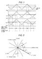
- Fig. 1 is a graph showing changes in PWM signals in the case where the determination of a three-phase short-circuit state, and the current-detection in the three-phase short-circuit state, are executed.
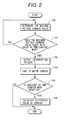
- Fig. 2 is a flow chart of the processing of current differences-detection, in which the current difference values in the three-phase short-circuit state are obtained, based on the change in the PWM signal corresponding to the maximum voltage command value.
- Fig. 3 is a vector diagram showing the principle of a two-phase short-circuit method.
- Fig. 4 is a graph showing changes in PWM signals in the case where the determination of a two-phase short-circuit state, and the current-detection in the two-phase short-circuit state, are executed.
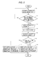
- Fig. 5 is a flow chart of the processing of current differences-detection, in which the current difference values in the two-phase short-circuit state are obtained.
- Fig. 6 is a diagram showing an example of the result of the magnetic pole position-calculation.
- Fig. 7 is a schematic block diagram showing the composition of the position-sensorless motor-control system including a digital filter.
- Fig. 8 is a schematic block diagram showing the digital filter shown in Fig. 7.
- Fig. 9 is a schematic block diagram showing the composition of another position-sensorless motor-control system.
- Fig. 10 is an illustration showing the relationship between the magnetic pole and the current difference vector in the three-phase short-circuit state of a synchronous motor.
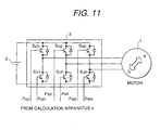
- Fig. 11 is a diagram showing an example of the composition of an inverter.
- a schematic block diagram indicating an example of the composition of a synchronous motor-control apparatus without a magnetic pole position sensor (referred to as a position-sensorless synchronous motor-control apparatus), to which the present invention is applied, is shown in Fig. 9. Since the present invention relates to a magnetic pole-detection method which does not use a magnetic pole position sensor, a position-sensorless motor-control system in this embodiment is explained below. However, the present invention is not restricted to a position-sensorless synchronous motor-control system, and can also be applied to a motor-control system with a magnetic pole position sensor. Such a motor-control system with a magnetic pole position sensor, to which the present invention is applied, can be used for detecting an anomaly in the position sensor, and can also function as a back-up position sensor.
- Fig. 9 shows a diagram showing the composition of a motor-control system in which a synchronous motor 1 is driven with direct current (referred to as DC) power fed from a battery 2.
- the DC voltage fed from the battery 2 is converted to the three-phase alternating current (referred to as AC) voltage by an inverter 3, and is applied to the synchronous motor 1.
- a command value for indicating the applied voltage namely, a three-phase AC voltage command value, is calculated by a digital calculation apparatus 4.
- a current command-generation unit 6 determines a d-axis current command id * and a q-axis current command iq * , corresponding to a torque command value Tr which is demanded of the synchronous motor 1.
- the d-axis indicates the magnetic pole direction in the rotor in the synchronous motor 1
- the q-axis indicate the direction perpendicular to the d-axis.
- the motor-control system controls motor current in the d-q rotating coordinate system.
- U-phase current iu and V-phase current iv detected by respective current sensors 5a and 5b, are taken into the digital calculatiion apparatus 4 via a current-detection unit 10 consisting of an A/D converter and so on, and are converted to a detected d-axis current value id ⁇ and a detected q-axis current value iq ⁇ , respectively.
- a current-control unit 7 determines a d-axis voltage command Vd * and a q-axis voltage command Vq * such that the difference between the command value id * and the detected value id ⁇ of the d-axis current, and the difference between the command value iq * and the detected value iq ⁇ of the q-axis current, are zero.
- a coordinate-conversion unit 8 converts the d-axis voltage command Vd * and the q-axis voltage command Vq * to three-phase AC voltage commands Vu * , Vv * , and Vw * , and sends them to a PWM signal-generation unit 9.
- the PWM signal-generation unit 9 converts the three-phase AC voltage commands Vu * , Vv * , and Vw * to PWM signals, and sends them to the inverter 3. Consequently, the respective voltage corresponding to the three-phase AC voltage commands Vu * , Vv * , and Vw * , is applied to the motor 1.
- the d-q rotating coordinate system rotates with a rotating angle ⁇ which is a magnetic pole position in the ⁇ - ⁇ rest coordinate system. Therefore, the detection of the magnetic pole position ⁇ in the rotor is necessary in the coordinate-conversion units 8 and 11. This detected magnetic pole position ⁇ is obtained by a magnetic pole position-detection means 14.
- composition and operations, of the position-sensorless synchronous motor-control system and the calculation apparatus situated in this motor-control system are such as those mentioned above.
- this motor-control system is explained as a torque-control system to which a torque command is input, it is possible to compose the motor-control system as a speed-control system in which a speed-control unit is added as an upper-level subsystem, and a speed command is input to the speed-control unit.
- a speed-control system an estimated speed ⁇ is obtained using the rate of change in the detected ⁇ , and this estimated speed ⁇ is used as a speed feed-back value.
- the magnetic pole position-detection method used in the magnetic pole position-detection means 14 is not restricted to a specific method.
- One effective position-detection method is a method in which a current difference in a short-circuit state of a synchronous motor is detected, and the magnetic polar position is obtained, based on the quantity and the direction of the current difference.
- This method in which "a current difference in a short-circuit state of a synchronous motor is detected, and the magnetic polar position is obtained, based on the quantity and the direction of the current difference", (hereafter referred to as a current difference type magnetic pole position-detection method), is briefly explained below.
- the magnetic pole position to be detected corresponds to the phase shift between the a-axis in the rest coordinate system and the d-axis in the rotating coordinate system, and is expressed by the equation (1).
- ⁇ ⁇ - ⁇
- ⁇ a phase of the current difference vector pis in a three-phase short-circuit state of a synchronous motor, from the ⁇ -axis
- ⁇ is a phase of the current difference vector pis, from the d-axis.
- the phase ⁇ is obtained by the equation (2).
- Ld and Lq are the d-axis inductance and the q-axisinductance, respectively
- R is the wound wire resistance
- ⁇ is the motor angular speed.
- the equation (2) is derived from the state equation of the motor in the three-phase short-circuit state.
- the motor angular speed ⁇ in the equation (2) is obtained from the rate of change in the detected magnetic pole position, and if the resistance R component can be neglected, the influence of an error in ⁇ can be neglected.
- the outline of the current difference type magnetic pole position-detection method has been explained above. This method can be applied to not only a salient-pole type synchronous motor but also a cylinder type synchronous motor. As explained above, in order to implement the current difference type magnetic pole position-detection method, it is necessary to determine the short-circuit state of the motor, and detect motor current corresponding with the short-circuit state. Therefore, an actual implementing way of the current difference type magnetic pole position-detection method is described below.
- the digital calculation apparatus 4 sends the PWM signals Pup, Pun, Pvp, Pvn, Pwp, and Pwn, (simply described as Pu, Pv, and Pw, in this figure), and controls switching elements Sup, Sun, Svp, Svn, Swp, and Swn, corresponding to the respective PWM signals.
- Pup and Pun ((Pvp and Pvn), and (Pwp and Pwn))
- Pup and Pun are a Hi-level signal and a Low-level signal, respectively.
- the motor 1 is in the three-phase short-circuit state.
- the PWM signals are generated in the digital calculation apparatus 4, it is possible to determine a short-circuit state of the motor 1 by examining the PWM signals generated in the digital calculation apparatus.
- Fig. 1 is a graph showing a concept of the three-phase short-circuit-determination, and changes in the PWM signals used for current detection in the three-phase short-circuit state.
- Fig. 1 is a simplified graph showing only the PWM signals in the upper arms which is turned to the active state by a Hi-level signal.
- the levels of all the PWM signals are the same at each crest or each trough of the PWM carrier wave. That is, the levels of the PWM signals indicate a Hi-level at every crest of the PWM carrier wave, and the levels of the PWM signals conversely indicate a Low-level at every trough of the PWM carrier wave.
- This situation means that since the same voltage is applied to the three phases of the motor 1, the motor 1 is in the three-phase short-circuit state.
- each of the three-phase short-circuit intervals is shown by a pair of thick arrow.
- the digital calculation apparatus 4 by detecting the motor current in synchronization with the rise and fall of the PWM signal with the narrowest width, the amount of current change, that is, the current difference in the interval corresponding to the narrowest width, is obtained.
- an interruption-trigger T1 is generated at the timing when the maximum or minimum value in the voltage command values for the three phases agrees with the value of the PWM carrier wave. Consequently, the current-detection unit 10 is started by the interruption-trigger T1, and the motor current is detected.
- the motor current can be detected by outputting the trigger T1 in synchronization with the PWM signals corresponding to both phases which receive the maximum voltage command value and the minimum voltage command value.
- Fig. 1 shows the interruption trigger-generation manner in the case where the trigger T1 is generated in synchronization with the PWM signals corresponding to both the phases which receive the maximum voltage command value and the minimum voltage command value.
- Fig. 2 shows the processes of detecting the current differences in the three-phase short-circuit state, based on the PWM signal corresponding to the phase receiving the maximum voltage command value.
- step 100 the phase receiving the maximum voltage command value is determined in the three phases.
- step 101 the time point at which the maximum voltage command value agrees with the PWM carrier wave is detected. That is, this time point is the rise point or the fall point of the PWM signal corresponding to the phase receiving the maximum voltage command value.
- step 101 If it is determined in step 101, that the maximum voltage command value agrees with the PWM carrier wave, the interruption trigger signal T1 is generated and output. Further, in step 103, the process of detecting the motor current is started in response to the trigger signal T1, and the motor current is input to the digital calculation apparatus 4.
- step 104 the gradient of the PWM carrier wave, at the time point when the maximum voltage command value agrees with the PWM carrier wave, is determined. If the gradient of the PWM carrier wave is positive, it is determined that this point is the start point of the three-phase short-circuit state, and only the process of inputting the motor current is executed. Conversely, if the gradient of the PWM carrier wave is negative, it is determined that this point is the end point of the three-phase short-circuit state, and after the motor current is input, the current differences are obtained using the current values detected at the start and end points of the three-phase short-circuit state, respectively.
- the above explanation is for the three-phase short-circuit-determination method and the current difference-calculation method used in this determination method.
- the flow chart of determining the three-phase short-circuit state is shown in Fig. 2, the determining of the three-phase short-circuit state is possible based on the PWM signal corresponding to the phase receiving the maximum voltage command value, or the PWM signals corresponding to both phases which receive the maximum and minimum voltage command values.
- a dead time interval is not considered in the flow chart shown in Fig. 2, if there is a dead time interval, it is necessary to generate the interruption signal T1 by taking the dead time interval into account.
- the execution timing of the magnetic pole position-calculation using the obtained current difference values is not restricted to a specific time point, it is desirable to finish this calculation before the next generation of the three-phase short-circuit begins.
- the current difference type magnetic pole position-detection method can be implemented by using the digital calculation apparatus 4.
- the magnetic pole position-detection method which uses the current differences in the three-phase short-circuit state of the motor, used for the synchronous motor-control apparatus of the above first embodiment, has been explained above.
- the time interval of the three-phase short-circuit state becomes very short, the current differences cannot be detected, depending on the performance of the calculation apparatus, and whether the magnetic pole position is well calculated or not. Under such conditions, it is useful to obtain the current differences in the interval in the two-phase short-circuit state, and estimate the current differences in the three-phase short-circuit state, using those current differences obtained in the two-phase short-circuit state.
- the current differences can be more reliably obtained in the two-phase short-circuit state than those in the three-phase short-circuit state.
- the method of estimating the current differences in the three-phase short-circuit state with the current differences obtained in the two-phase short-circuit state is referred to as a two-phase short-circuit method.
- FIG. 3 is a vector diagram for explaining the method in which, by using the current difference pi ⁇ in the direction where the current difference does not receive an influence of the applied voltage in the V and W-phase short-circuit state, and the current difference pi ⁇ ' in the direction where the current difference does not receive an influence of the applied voltage in the W and V-phase short-circuit state, the current difference pis in the three-phase short-circuit state is estimated. Since the current difference in the three-phase short-circuit state is estimated with the current differences in the two directions in the two kinds of two-phase short-circuit states as shown in Fig. 3, it is necessary to determine a combination of two kinds of two-phase short-circuits, and to detect the current difference in a time interval in each kind of two-phase short-circuit.
- Fig. 4 shows changes of PWM signals in the case where each two-phase short-circuit state is determined, and the current difference is detected in this two-phase short-circuit state.
- Fig. 1 is a simplified graph showing only the PWM signals in the upper arms which are turned to the active state by a Hi-level signal.
- each two-phase short-circuit state is indicated by a pair of thick arrows.
- the phases which turn to a short-circuit state are determined, based on the voltage command indicating an intermediate value in the three-phase voltage commands.
- the digital calculation apparatus 4 detects the motor current in synchronization with the rise and the fall of the PWM signal corresponding to the voltage command with an intermediate value, and obtains the amount of current change, that is, the current difference, in the time interval of this two-phase short-circuit state. Specifically, at the timing when the intermediate voltage command value in the voltage command values for the three phases agrees with the value of the PWM carrier wave, the interruption trigger T2 is generated, and the current-detection unit 10 starts the motor current-detection, on receiving the trigger T2. In this way of current detection, the current differences in the three-phase short-circuit state is estimated by using the two current difference values obtained in the successive two time intervals in the two-phase short-circuit state.
- step 110 the phase for which voltage command value is an intermediate value
- step 111 the time point at which the intermediate voltage command value agrees with the value of the PWM carrier wave is detected. That is, this time point corresponds to the rise point or the fall point of the PWM signal for the intermediate voltage command.
- the interruption trigger T2 is generated in step 112, and the motor current is taken in to start the detection of the motor current in response to the trigger T2 in step 113.
- step 114 the current difference value in the two-phase short-circuit of this time is calculated using two current difference values detected at the previous and present detection time points. Furthermore, in step 115, the gradient of the PWM carrier wave at the time point when the intermediate voltage command value agrees with the value of the PWM carrier wave, is determined. If the gradient is positive, it is determined that two phases corresponding to the intermediate and maximum voltage command values are in the two-phase short-circuit state. Conversely, if the gradient is negative, it is determined that two phases corresponding to the intermediate and minimum voltage command values are in the two-phase short-circuit state.
- the above-explained processing is the methods of determining each two-phase short-circuit state, and calculating the current difference value in this two-phase short-circuit state.
- the timing of calculating each current difference in the direction in which the current difference does not receive an influence of the applied voltage, and the magnetic pole position, using the calculated current differences, is not restricted to a specific time point. However, if the timing of this calculation is delayed, a phase error occurs due to the rotation of the motor, and phase correction for the phase error is necessary.
- a dead time interval is not considered in the flow chart shown in Fig. 5, if there is a dead time interval, it is necessary to generate the interruption signal T2 by taking the dead time interval into account.
- the current difference type magnetic pole position-detection method can be implemented by using the digital calculation apparatus 4.
- the motor current is detected in synchronization with the phase corresponding to the maximum or minimum voltage command value.
- the motor current is detected in synchronization with the phase corresponding to the intermediate voltage command value.
- the phase with which the detection of the motor current is synchronized is not fixed to only one phase corresponding to the maximum, intermediate, or minimum voltage command value, and can be switched. The ability to switch such a phase is particularly necessary between the three-phase short-circuit, in which the current differences are directly calculated in the three-phase short-circuit state, and the two-phase short-circuit method.
- One method of removing such harmonic components is a digital-filter which is composed in the digital calculation apparatus in this embodiment.
- the composition of a position-sensorless control system is shown in Fig. 7.
- a generally used low-pass filter can be applied to the digital filter 20 shown in Fig. 7, since a frequency of a harmonic wave contained in the calculated magnetic pole position changes depending on the rotational frequency of the motor, it is favorable that a cut-off frequency set up to the digital filter 20 can be changed.
- the digital filter 20 is composed, as shown in Fig. 8, so that its cut-off frequency is changed according to the motor speed.
- the detected magnetic pole position ⁇ is input to a speed-calculation unit 21, and the estimated rotational frequency ⁇ of the motor is calculated.
- the estimated rotational frequency ⁇ can be obtained by calculating the rate of change in the magnetic pole position ⁇ .
- a cut-off frequency unit 22 determines the cut-off frequency of a digital filter 23, based on the estimated rotational frequency ⁇ .
- the cut-off frequency is set as a frequency such that it is lower than the removed harmonic frequency, and a delay of the fundamental component, due to the filtering with the cut-off frequency, can be ignored in the motor-control.
- the method of implementing the magnetic pole-detection method which uses a digital calculation apparatus such as a microcomputer, is described above, and this method is suitable for a control apparatus of an electrical car and an electrical vehicle such as a hybrid car.
- a microcomputer is mainly used in a control apparatus of an electrical cal, and an electrical vehicle; a permanent magnet type synchronous motor has been also mainly used from the view point of downsizing and efficiency-improvement of a motor; and a sensorless control method is desired for an electrical car, and an electrical vehicle in light of the need for high reliability and low cost.
Landscapes
- Engineering & Computer Science (AREA)
- Power Engineering (AREA)
- Transportation (AREA)
- Mechanical Engineering (AREA)
- Life Sciences & Earth Sciences (AREA)
- Sustainable Development (AREA)
- Sustainable Energy (AREA)
- Control Of Ac Motors In General (AREA)
- Control Of Motors That Do Not Use Commutators (AREA)
- Electric Propulsion And Braking For Vehicles (AREA)
- Inverter Devices (AREA)
Abstract
Description

Claims (7)
- A synchronous motor-control apparatus including a synchronous motor (1), a PWM inverter (3) for driving said synchronous motor (1), and a digital calculation apparatus (4) for controlling said PWM inverter (3), said synchronous motor-control apparatus comprising:magnetic pole position-detection means (14), situated in said digital calculation apparatus (4), for obtaining a magnetic pole position based on current, which flows in said synchronous motor (1), and is input to said digital calculation apparatus (4); andcontrol means for controlling said synchronous motor (1) based on the detected magnetic pole position;wherein said magnetic pole position-detection means (14) takes in the current, which flows in said synchronous motor (1), by operating an A/D converter with an interruption signal generated by said position-detection means (14) in synchronization with PWM signals for driving said PWM inverter (3).
- A synchronous motor-control apparatus according to claim 1, wherein said synchronous motor (1) is a three-phase alternating current synchronous motor, and said magnetic pole position-detection means (14) takes in the current flowing in said motor (1) by operating an A/D converter with an interruption signal generated by said position-detection means (14) in synchronization with PWM signal corresponding to at least one of the maximum value and the minimum value, of three-phase alternating current voltage signals sent to said motor (1) .
- A synchronous motor-control apparatus according to claim 1, wherein said synchronous motor (1) is a three-phase alternating current synchronous motor, and said magnetic pole position-detection means (14) takes in the current flowing in said motor (1) by operating an A/D converter with an interruption signal generated by said position-detection means (14) in synchronization with PWM signal corresponding to an intermediate value of three-phase alternating current voltage signals sent to said motor (1).
- A synchronous motor-control apparatus according to claim 1, wherein said synchronous motor (1) is a three-phase alternating current synchronous motor, and said magnetic pole position-detection means (14) switches the PWM signal with which the generation of said trigger signal is synchronized, between at least two out of three phases corresponding to the maximum, intermediate, and minimum voltage command values for said motor (1).
- A synchronous motor-control apparatus including a synchronous motor (1), a PWM inverter (3) for driving said synchronous motor (1), and a digital calculation apparatus (4) for controlling said PWM inverter (3), said synchronous motor-control apparatus comprising:magnetic pole position-detection means (14), situated in said digital calculation apparatus (4), for obtaining a magnetic pole position based on current, which flows in said synchronous motor (1), and is input to said digital calculation apparatus (4); andcontrol means for controlling said synchronous motor (1) based on the detected magnetic pole position;wherein said magnetic pole position-detection means (14) detects a potential state of each phase in said synchronous motor (1), based on PWM signals for three phases, for driving said PWM inverter (3).
- A synchronous motor-control apparatus including a synchronous motor (1), a PWM inverter (3) for driving said synchronous motor (1), and a digital calculation apparatus (4) for controlling said PWM inverter (3), said synchronous motor-control apparatus comprising:magnetic pole position-detection means (14), situated in said digital calculation apparatus (4), for obtaining a magnetic pole position based on current, which flows in said synchronous motor (1), and is input to said digital calculation apparatus (4); andcontrol means for controlling said synchronous motor (1) based on the detected magnetic pole position;wherein said magnetic pole position-detection means (14) includes a digital filter (20) for removing harmonic components contained in said obtained magnetic pole position, and changes a cut-off frequency of said digital filter (20), in accordance with a drive frequency of said motor (1).
- A vehicle comprising a synchronous motor (1) used as a driving force device, and a synchronous motor control-apparatus of said motor (1), said control apparatus according to any one of claims 1 - 6.
Applications Claiming Priority (2)
| Application Number | Priority Date | Filing Date | Title |
|---|---|---|---|
| JP2000056046A JP3681318B2 (en) | 2000-02-28 | 2000-02-28 | Synchronous motor control device and vehicle using the same |
| JP2000056046 | 2000-02-28 |
Publications (3)
| Publication Number | Publication Date |
|---|---|
| EP1128543A2 true EP1128543A2 (en) | 2001-08-29 |
| EP1128543A3 EP1128543A3 (en) | 2002-09-11 |
| EP1128543B1 EP1128543B1 (en) | 2007-08-29 |
Family
ID=18577072
Family Applications (1)
| Application Number | Title | Priority Date | Filing Date |
|---|---|---|---|
| EP00118114A Expired - Lifetime EP1128543B1 (en) | 2000-02-28 | 2000-08-25 | Synchronous motor-control apparatus and vehicle using the control apparatus |
Country Status (4)
| Country | Link |
|---|---|
| US (1) | US6501243B1 (en) |
| EP (1) | EP1128543B1 (en) |
| JP (1) | JP3681318B2 (en) |
| DE (1) | DE60036192T2 (en) |
Cited By (3)
| Publication number | Priority date | Publication date | Assignee | Title |
|---|---|---|---|---|
| US6914408B2 (en) * | 2001-02-27 | 2005-07-05 | Hitachi, Ltd. | Motor control apparatus and electric vehicle using same |
| EP1630946A3 (en) * | 2004-08-24 | 2009-12-09 | Samsung Electronics Co., Ltd. | Initial motor driving method and apparatus |
| US8823301B2 (en) | 2012-11-05 | 2014-09-02 | Whirlpool Corporation | Method and device for detecting rotor position in a permanent magnet synchronous motor-driven washing machine |
Families Citing this family (73)
| Publication number | Priority date | Publication date | Assignee | Title |
|---|---|---|---|---|
| US6459225B1 (en) * | 1999-04-27 | 2002-10-01 | Canon Kabushiki Kaisha | Servo-control apparatus for motor |
| JP4420170B2 (en) * | 2000-03-27 | 2010-02-24 | 三菱電機株式会社 | Synchronous machine rotation state detection device and synchronous machine rotation state detection method |
| JP3695342B2 (en) * | 2001-04-11 | 2005-09-14 | 株式会社日立製作所 | Electric motor control device |
| JP3867518B2 (en) * | 2001-06-06 | 2007-01-10 | 株式会社日立製作所 | Sensorless control system for synchronous motor |
| JP4075338B2 (en) * | 2001-07-18 | 2008-04-16 | 株式会社豊田自動織機 | Control method of electric compressor |
| JP3503894B2 (en) * | 2001-09-26 | 2004-03-08 | 日本サーボ株式会社 | Driving device for stepping motor |
| DE10206191B4 (en) * | 2001-11-27 | 2006-02-02 | Siemens Ag | Method for field-oriented control of a permanent-magnet synchronous machine with reluctance torque |
| WO2003067748A1 (en) * | 2002-02-07 | 2003-08-14 | Mitsubishi Denki Kabushiki Kaisha | Device for detecting magnetic pole of synchronous ac motor, and magnetic pole detecting method therefor |
| EP1479157B1 (en) * | 2002-02-13 | 2006-12-06 | Continental Teves AG & Co. oHG | Method for the detection of abnormalities of electric motors |
| JP3692085B2 (en) * | 2002-02-21 | 2005-09-07 | 株式会社東芝 | Motor control method and apparatus |
| JP3661864B2 (en) * | 2002-03-19 | 2005-06-22 | 日本サーボ株式会社 | Stepping motor drive device |
| US6914399B2 (en) * | 2002-07-09 | 2005-07-05 | Delphi Technologies | Active deadtime control for improved torque ripple performance in electric machines |
| JP4241218B2 (en) * | 2003-06-27 | 2009-03-18 | 株式会社日立産機システム | AC motor control device and AC motor system |
| US7242163B2 (en) * | 2003-08-26 | 2007-07-10 | Delphi Technologies, Inc. | System and method for clamp current regulation in field-weakening operation of permanent magnet (PM) machines |
| US7136733B2 (en) * | 2003-08-28 | 2006-11-14 | Motorola, Inc. | Fault detection in an electric power-assisted steering system |
| JP2005130673A (en) * | 2003-10-27 | 2005-05-19 | Fuji Electric Systems Co Ltd | Control device for permanent magnet type synchronous motor |
| US7049778B2 (en) * | 2004-02-09 | 2006-05-23 | Nippon Yusoki Co., Ltd. | Inverter control apparatus and inverter control method |
| US7075264B2 (en) * | 2004-03-31 | 2006-07-11 | Honeywell International Inc. | Instantaneous power floating frame controller |
| US9496720B2 (en) | 2004-08-20 | 2016-11-15 | Midtronics, Inc. | System for automatically gathering battery information |
| US20060043923A1 (en) * | 2004-08-31 | 2006-03-02 | Baker Donal E | Performance enhancement for motor field oriented control system |
| JP4581574B2 (en) * | 2004-09-08 | 2010-11-17 | 株式会社ジェイテクト | Motor control device and electric power steering device |
| JP4592385B2 (en) * | 2004-10-27 | 2010-12-01 | 株式会社東芝 | Control device for synchronous machine |
| US7211984B2 (en) * | 2004-11-09 | 2007-05-01 | General Motors Corporation | Start-up and restart of interior permanent magnet machines |
| JP2006238631A (en) * | 2005-02-25 | 2006-09-07 | Mitsubishi Heavy Ind Ltd | MOTOR CONTROLLING METHOD USING Id/Iq TABLE |
| KR100657489B1 (en) * | 2005-03-08 | 2006-12-19 | 엘지전자 주식회사 | Method and device for starting determination of motor without sensor |
| JP3927584B2 (en) * | 2005-10-26 | 2007-06-13 | 三菱電機株式会社 | Power control device for automobile |
| JP4413185B2 (en) * | 2005-12-08 | 2010-02-10 | 三洋電機株式会社 | Motor drive control device |
| JP4716118B2 (en) * | 2006-03-29 | 2011-07-06 | 株式会社ジェイテクト | Motor control device |
| US7549504B2 (en) | 2006-07-28 | 2009-06-23 | Delphi Technologies, Inc. | Quadrant dependent active damping for electric power steering |
| US7543679B2 (en) | 2006-07-28 | 2009-06-09 | Delphi Technologies, Inc. | Compensation of periodic sensor errors in electric power steering systems |
| US7725227B2 (en) | 2006-12-15 | 2010-05-25 | Gm Global Technology Operations, Inc. | Method, system, and apparatus for providing enhanced steering pull compensation |
| JP4930085B2 (en) * | 2007-02-08 | 2012-05-09 | 株式会社富士通ゼネラル | Phase detection method, phase detection device, synchronous motor control method, and synchronous motor control device |
| JP5311864B2 (en) * | 2007-04-13 | 2013-10-09 | 三洋電機株式会社 | Motor control device |
| GB2491304B (en) * | 2007-07-17 | 2013-01-09 | Midtronics Inc | Battery tester and electric vehicle |
| US20110050209A1 (en) * | 2007-10-09 | 2011-03-03 | Rainer Nase | Method and apparatus for unambiguous determination of the rotor position of an electrical machine |
| JP4508237B2 (en) * | 2007-12-19 | 2010-07-21 | 株式会社デンソー | Rotating machine control device |
| US8179065B2 (en) * | 2008-04-30 | 2012-05-15 | Rockwell Automation Technologies, Inc. | Position sensorless control of permanent magnet motor |
| JP5526975B2 (en) * | 2009-05-13 | 2014-06-18 | 株式会社安川電機 | Electric motor control device and control method thereof |
| JP5375480B2 (en) * | 2009-09-18 | 2013-12-25 | 株式会社デンソー | Rotating machine control device |
| US9588185B2 (en) | 2010-02-25 | 2017-03-07 | Keith S. Champlin | Method and apparatus for detecting cell deterioration in an electrochemical cell or battery |
| GB201004049D0 (en) * | 2010-03-11 | 2010-04-28 | Trw Ltd | Electric motor control |
| US10046649B2 (en) | 2012-06-28 | 2018-08-14 | Midtronics, Inc. | Hybrid and electric vehicle battery pack maintenance device |
| JP5829681B2 (en) | 2010-06-03 | 2015-12-09 | ミッドトロニクス インコーポレイテッド | Maintenance of battery packs for electric vehicles |
| US11740294B2 (en) | 2010-06-03 | 2023-08-29 | Midtronics, Inc. | High use battery pack maintenance |
| US10429449B2 (en) | 2011-11-10 | 2019-10-01 | Midtronics, Inc. | Battery pack tester |
| CN103386893A (en) * | 2012-05-07 | 2013-11-13 | 庄嘉明 | Motor assembly capable of switching energy storage device in real time, switching method and transportation tool |
| US11325479B2 (en) | 2012-06-28 | 2022-05-10 | Midtronics, Inc. | Hybrid and electric vehicle battery maintenance device |
| US9851411B2 (en) | 2012-06-28 | 2017-12-26 | Keith S. Champlin | Suppressing HF cable oscillations during dynamic measurements of cells and batteries |
| CN102723889B (en) * | 2012-07-03 | 2014-11-05 | 华为技术有限公司 | Inverter and pulse width modulation (PWM) method thereof |
| US10843574B2 (en) | 2013-12-12 | 2020-11-24 | Midtronics, Inc. | Calibration and programming of in-vehicle battery sensors |
| US9923289B2 (en) | 2014-01-16 | 2018-03-20 | Midtronics, Inc. | Battery clamp with endoskeleton design |
| US10473555B2 (en) | 2014-07-14 | 2019-11-12 | Midtronics, Inc. | Automotive maintenance system |
| US10222397B2 (en) | 2014-09-26 | 2019-03-05 | Midtronics, Inc. | Cable connector for electronic battery tester |
| US10317468B2 (en) | 2015-01-26 | 2019-06-11 | Midtronics, Inc. | Alternator tester |
| US9966676B2 (en) | 2015-09-28 | 2018-05-08 | Midtronics, Inc. | Kelvin connector adapter for storage battery |
| JP6103125B1 (en) * | 2015-10-29 | 2017-03-29 | ダイキン工業株式会社 | Speed command correction device, primary magnetic flux command generation device |
| DE102016207375A1 (en) | 2016-04-29 | 2017-11-02 | Robert Bosch Gmbh | Method and device for controlling an electric machine |
| US10608353B2 (en) | 2016-06-28 | 2020-03-31 | Midtronics, Inc. | Battery clamp |
| US12320857B2 (en) | 2016-10-25 | 2025-06-03 | Midtronics, Inc. | Electrical load for electronic battery tester and electronic battery tester including such electrical load |
| US11054480B2 (en) | 2016-10-25 | 2021-07-06 | Midtronics, Inc. | Electrical load for electronic battery tester and electronic battery tester including such electrical load |
| US11513160B2 (en) | 2018-11-29 | 2022-11-29 | Midtronics, Inc. | Vehicle battery maintenance device |
| US11075597B2 (en) | 2018-12-04 | 2021-07-27 | Aisin Seiki Kabushiki Kaisha | Motor control device |
| US11566972B2 (en) | 2019-07-31 | 2023-01-31 | Midtronics, Inc. | Tire tread gauge using visual indicator |
| US11545839B2 (en) | 2019-11-05 | 2023-01-03 | Midtronics, Inc. | System for charging a series of connected batteries |
| US11668779B2 (en) | 2019-11-11 | 2023-06-06 | Midtronics, Inc. | Hybrid and electric vehicle battery pack maintenance device |
| US11474153B2 (en) | 2019-11-12 | 2022-10-18 | Midtronics, Inc. | Battery pack maintenance system |
| DE102020216599A1 (en) | 2019-12-31 | 2021-07-01 | Midtronics, Inc. | Intelligent module interface for a battery maintenance device |
| US11973202B2 (en) | 2019-12-31 | 2024-04-30 | Midtronics, Inc. | Intelligent module interface for battery maintenance device |
| US11486930B2 (en) | 2020-01-23 | 2022-11-01 | Midtronics, Inc. | Electronic battery tester with battery clamp storage holsters |
| US12517178B2 (en) | 2021-05-27 | 2026-01-06 | Midtronics, Inc. | Battery monitoring system |
| US12555965B2 (en) | 2021-08-24 | 2026-02-17 | Midtronics, Inc. | Power adapter for automotive vehicle maintenance device |
| US12330513B2 (en) | 2022-02-14 | 2025-06-17 | Midtronics, Inc. | Battery maintenance device with high voltage connector |
| US12392833B2 (en) | 2022-05-09 | 2025-08-19 | Midtronics, Inc. | Electronic battery tester |
Family Cites Families (5)
| Publication number | Priority date | Publication date | Assignee | Title |
|---|---|---|---|---|
| AT402773B (en) * | 1993-08-16 | 1997-08-25 | Elin Energieanwendung | Method for state identification and magnetization of an inverter-fed (inverter-supplied) asynchronous machine which preferably has no position transmitter or rotation speed transmitter, having an unknown magnetization state, and a circuit arrangement or carrying out this method |
| JP3312472B2 (en) | 1994-03-01 | 2002-08-05 | 富士電機株式会社 | Magnetic pole position detection device for motor |
| FI96467C (en) * | 1994-06-08 | 1996-06-25 | Abb Industry Oy | Method for defining the rotational speed, magnitude and momentum of a flow |
| JP3278032B2 (en) * | 1994-06-14 | 2002-04-30 | 富士電機株式会社 | Rotor pole polarity detection method for permanent magnet synchronous motor |
| JP3312520B2 (en) * | 1995-01-24 | 2002-08-12 | 富士電機株式会社 | Magnetic pole position detection device for motor |
-
2000
- 2000-02-28 JP JP2000056046A patent/JP3681318B2/en not_active Expired - Lifetime
- 2000-08-25 DE DE60036192T patent/DE60036192T2/en not_active Expired - Lifetime
- 2000-08-25 EP EP00118114A patent/EP1128543B1/en not_active Expired - Lifetime
- 2000-08-31 US US09/652,653 patent/US6501243B1/en not_active Expired - Lifetime
Cited By (3)
| Publication number | Priority date | Publication date | Assignee | Title |
|---|---|---|---|---|
| US6914408B2 (en) * | 2001-02-27 | 2005-07-05 | Hitachi, Ltd. | Motor control apparatus and electric vehicle using same |
| EP1630946A3 (en) * | 2004-08-24 | 2009-12-09 | Samsung Electronics Co., Ltd. | Initial motor driving method and apparatus |
| US8823301B2 (en) | 2012-11-05 | 2014-09-02 | Whirlpool Corporation | Method and device for detecting rotor position in a permanent magnet synchronous motor-driven washing machine |
Also Published As
| Publication number | Publication date |
|---|---|
| DE60036192D1 (en) | 2007-10-11 |
| EP1128543B1 (en) | 2007-08-29 |
| JP2001245498A (en) | 2001-09-07 |
| US6501243B1 (en) | 2002-12-31 |
| JP3681318B2 (en) | 2005-08-10 |
| EP1128543A3 (en) | 2002-09-11 |
| DE60036192T2 (en) | 2008-05-21 |
Similar Documents
| Publication | Publication Date | Title |
|---|---|---|
| US6501243B1 (en) | Synchronous motor-control apparatus and vehicle using the control apparatus | |
| JP3695342B2 (en) | Electric motor control device | |
| CN101160713B (en) | Controller for ac motor | |
| US6771039B2 (en) | Motor control apparatus and method | |
| EP1958325B1 (en) | Control apparatus and method for motor drive system | |
| JP4067949B2 (en) | Motor control device | |
| JP4406552B2 (en) | Electric motor control device | |
| US8664901B2 (en) | Method and system for estimating electrical angular speed of a permanent magnet machine | |
| JPH10327600A (en) | Drive system for permanent magnet type synchronous machine and drive control method for electric vehicle using the same | |
| JP2002262591A (en) | Motor control device and electric vehicle using the same | |
| JPH11308704A (en) | Electric vehicle control device and control method | |
| JPH0970196A (en) | Discharge device for storage means inside inverter | |
| JP2003134898A (en) | Sensorless control device and control method for synchronous generator | |
| JP3675431B2 (en) | Electric motor drive device | |
| KR101989596B1 (en) | System and method for controlling motor | |
| JP2011050183A (en) | Inverter device | |
| US20110062904A1 (en) | Alternating current motor control system | |
| JP4590761B2 (en) | Control device for permanent magnet type synchronous motor | |
| JP5482050B2 (en) | Motor control device and motor phase loss diagnosis method | |
| JP3598909B2 (en) | Synchronous motor control device, electric vehicle control device, and synchronous motor control method | |
| JP2019208329A (en) | Sensorless vector control device and sensorless vector control method | |
| JP2003033075A (en) | Synchronous motor control device and electric vehicle | |
| KR102263027B1 (en) | Control method in the critical sention for single shunt sensorless pmsm | |
| JP4391480B2 (en) | Control device for electric motor for vehicle | |
| JP2024165742A (en) | MOTOR CONTROL DEVICE AND MOTOR CONTROL METHOD |
Legal Events
| Date | Code | Title | Description |
|---|---|---|---|
| PUAI | Public reference made under article 153(3) epc to a published international application that has entered the european phase |
Free format text: ORIGINAL CODE: 0009012 |
|
| AK | Designated contracting states |
Kind code of ref document: A2 Designated state(s): AT BE CH CY DE DK ES FI FR GB GR IE IT LI LU MC NL PT SE |
|
| AX | Request for extension of the european patent |
Free format text: AL;LT;LV;MK;RO;SI |
|
| PUAL | Search report despatched |
Free format text: ORIGINAL CODE: 0009013 |
|
| AK | Designated contracting states |
Kind code of ref document: A3 Designated state(s): AT BE CH CY DE DK ES FI FR GB GR IE IT LI LU MC NL PT SE |
|
| AX | Request for extension of the european patent |
Free format text: AL;LT;LV;MK;RO;SI |
|
| 17P | Request for examination filed |
Effective date: 20030108 |
|
| AKX | Designation fees paid |
Designated state(s): DE FR GB |
|
| 17Q | First examination report despatched |
Effective date: 20031201 |
|
| GRAP | Despatch of communication of intention to grant a patent |
Free format text: ORIGINAL CODE: EPIDOSNIGR1 |
|
| GRAS | Grant fee paid |
Free format text: ORIGINAL CODE: EPIDOSNIGR3 |
|
| GRAA | (expected) grant |
Free format text: ORIGINAL CODE: 0009210 |
|
| RAP1 | Party data changed (applicant data changed or rights of an application transferred) |
Owner name: HITACHI, LTD. |
|
| AK | Designated contracting states |
Kind code of ref document: B1 Designated state(s): DE FR GB |
|
| REG | Reference to a national code |
Ref country code: GB Ref legal event code: FG4D |
|
| REF | Corresponds to: |
Ref document number: 60036192 Country of ref document: DE Date of ref document: 20071011 Kind code of ref document: P |
|
| EN | Fr: translation not filed | ||
| ET | Fr: translation filed | ||
| REG | Reference to a national code |
Ref country code: FR Ref legal event code: EERR Free format text: CORRECTION DE BOPI 08/17 - BREVETS EUROPEENS DONT LA TRADUCTION N A PAS ETE REMISE A L INPI. IL Y A LIEU DE SUPPRIMER : LA MENTION DE LA NON-REMISE LA REMISE DE LA TRADUCTION EST PUBLIEE DANS LE PRESENT BOPI. |
|
| PLBE | No opposition filed within time limit |
Free format text: ORIGINAL CODE: 0009261 |
|
| STAA | Information on the status of an ep patent application or granted ep patent |
Free format text: STATUS: NO OPPOSITION FILED WITHIN TIME LIMIT |
|
| 26N | No opposition filed |
Effective date: 20080530 |
|
| PGFP | Annual fee paid to national office [announced via postgrant information from national office to epo] |
Ref country code: GB Payment date: 20080718 Year of fee payment: 9 |
|
| GBPC | Gb: european patent ceased through non-payment of renewal fee |
Effective date: 20090825 |
|
| PG25 | Lapsed in a contracting state [announced via postgrant information from national office to epo] |
Ref country code: GB Free format text: LAPSE BECAUSE OF NON-PAYMENT OF DUE FEES Effective date: 20090825 |
|
| REG | Reference to a national code |
Ref country code: FR Ref legal event code: PLFP Year of fee payment: 16 |
|
| PGFP | Annual fee paid to national office [announced via postgrant information from national office to epo] |
Ref country code: DE Payment date: 20150818 Year of fee payment: 16 |
|
| PGFP | Annual fee paid to national office [announced via postgrant information from national office to epo] |
Ref country code: FR Payment date: 20150629 Year of fee payment: 16 |
|
| REG | Reference to a national code |
Ref country code: DE Ref legal event code: R119 Ref document number: 60036192 Country of ref document: DE |
|
| REG | Reference to a national code |
Ref country code: FR Ref legal event code: ST Effective date: 20170428 |
|
| PG25 | Lapsed in a contracting state [announced via postgrant information from national office to epo] |
Ref country code: FR Free format text: LAPSE BECAUSE OF NON-PAYMENT OF DUE FEES Effective date: 20160831 Ref country code: DE Free format text: LAPSE BECAUSE OF NON-PAYMENT OF DUE FEES Effective date: 20170301 |