EP1479157B1 - Method for the detection of abnormalities of electric motors - Google Patents
Method for the detection of abnormalities of electric motors Download PDFInfo
- Publication number
- EP1479157B1 EP1479157B1 EP03739438A EP03739438A EP1479157B1 EP 1479157 B1 EP1479157 B1 EP 1479157B1 EP 03739438 A EP03739438 A EP 03739438A EP 03739438 A EP03739438 A EP 03739438A EP 1479157 B1 EP1479157 B1 EP 1479157B1
- Authority
- EP
- European Patent Office
- Prior art keywords
- motor
- estimated
- torque
- electric motor
- current
- Prior art date
- Legal status (The legal status is an assumption and is not a legal conclusion. Google has not performed a legal analysis and makes no representation as to the accuracy of the status listed.)
- Expired - Lifetime
Links
- 238000000034 method Methods 0.000 title claims description 33
- 238000001514 detection method Methods 0.000 title claims description 21
- 230000005856 abnormality Effects 0.000 title 1
- 238000004804 winding Methods 0.000 claims description 8
- 230000033001 locomotion Effects 0.000 claims description 5
- 230000001771 impaired effect Effects 0.000 claims description 2
- 238000012544 monitoring process Methods 0.000 description 7
- 230000008901 benefit Effects 0.000 description 4
- 230000001419 dependent effect Effects 0.000 description 3
- 230000001360 synchronised effect Effects 0.000 description 3
- 238000012360 testing method Methods 0.000 description 3
- 230000002950 deficient Effects 0.000 description 2
- 238000010586 diagram Methods 0.000 description 2
- 238000005259 measurement Methods 0.000 description 2
- 238000004088 simulation Methods 0.000 description 2
- 230000001133 acceleration Effects 0.000 description 1
- 230000003044 adaptive effect Effects 0.000 description 1
- 230000000712 assembly Effects 0.000 description 1
- 238000000429 assembly Methods 0.000 description 1
- 230000033228 biological regulation Effects 0.000 description 1
- 230000008859 change Effects 0.000 description 1
- 238000003745 diagnosis Methods 0.000 description 1
- 230000000694 effects Effects 0.000 description 1
- 238000011156 evaluation Methods 0.000 description 1
- 230000006698 induction Effects 0.000 description 1
- 238000012423 maintenance Methods 0.000 description 1
- 239000002244 precipitate Substances 0.000 description 1
- 230000008569 process Effects 0.000 description 1
- 230000009467 reduction Effects 0.000 description 1
- 230000008439 repair process Effects 0.000 description 1
- 238000012546 transfer Methods 0.000 description 1
- 230000003313 weakening effect Effects 0.000 description 1
Images


Classifications
-
- H—ELECTRICITY
- H02—GENERATION; CONVERSION OR DISTRIBUTION OF ELECTRIC POWER
- H02P—CONTROL OR REGULATION OF ELECTRIC MOTORS, ELECTRIC GENERATORS OR DYNAMO-ELECTRIC CONVERTERS; CONTROLLING TRANSFORMERS, REACTORS OR CHOKE COILS
- H02P29/00—Arrangements for regulating or controlling electric motors, appropriate for both AC and DC motors
- H02P29/02—Providing protection against overload without automatic interruption of supply
-
- H—ELECTRICITY
- H02—GENERATION; CONVERSION OR DISTRIBUTION OF ELECTRIC POWER
- H02P—CONTROL OR REGULATION OF ELECTRIC MOTORS, ELECTRIC GENERATORS OR DYNAMO-ELECTRIC CONVERTERS; CONTROLLING TRANSFORMERS, REACTORS OR CHOKE COILS
- H02P6/00—Arrangements for controlling synchronous motors or other dynamo-electric motors using electronic commutation dependent on the rotor position; Electronic commutators therefor
- H02P6/34—Modelling or simulation for control purposes
Landscapes
- Engineering & Computer Science (AREA)
- Power Engineering (AREA)
- Control Of Motors That Do Not Use Commutators (AREA)
Description
Die Erfindung betrifft ein Verfahren zur Fehlererkennung eines bürstenlosen Elektromotors. Ein solches Verfahren ist aus der US 6 112 156 bekannt geworden.The invention relates to a method for fault detection of a brushless electric motor. Such a method has become known from US 6,112,156.
Bürstenlose Elektromotoren bzw. elektronisch kommutierte Elektromotoren gewinnen zunehmend an Bedeutung. Sie ersetzen insbesondere bürstenbehaftete Elektromotoren in vielen technische Anwendungen. Die Vorteile gegenüber bürstenbehafteten Motoren liegen vor allem im geringen Wartungsaufwand durch Wegfall der Verschleiß unterworfenen Kommutatorbürsten und des prinzipiell höheren Wirkungsgrades durch Wegfall der durch die Bürstenübergangswiderstände hervorgerufenen Kommtatorverluste. Darüber hinaus lassen sich in Verbindung mit "intelligenten" elektronischen Kommutierungseinrichtungen Funktionen realisieren, die mit bürstenbehafteten Motoren nicht möglich oder nur mit einem erheblichen mechanischen Mehraufwand zu erreichen sind. Hierzu zählen der Betrieb im Bereich schwacher Felder oder Feldschwächemodus die Realisierung einer sehr niedrigen Welligkeit des Antriebsmoments.Brushless electric motors or electronically commutated electric motors are becoming increasingly important. They replace in particular brushed electric motors in many technical applications. The advantages over brushless motors are mainly in the low maintenance costs by eliminating the subject commutator brushes and the principle higher efficiency by eliminating caused by the brush contact resistors Kommtatorverluste. In addition, functions can be realized in conjunction with "intelligent" electronic commutation devices, which are not possible with brushed motors or can only be achieved with a considerable mechanical outlay. These include the operation in the field of weak fields or field weakening mode, the realization of a very low ripple of the drive torque.
Da bei bürstenlosen Elektromotoren die Funktionen mechanischer, inherent weitgehend sicherer und zuverlässiger Komponenten, in diesem Fall die Kommutatorbürsten eines Kommutatormotors, durch mechatronische Baugruppen ersetzt werden, ist durch geeignete Maßnahmen die Ausfallsicherheit sicherzustellen. Bedingt durch die relativ hohe Komplexität der Kommutierungselektronik bürstenloser Motoren ergeben sich auch relativ viele Fehlermöglichkeiten.Since in brushless electric motors the functions of mechanical, inherently largely safe and reliable components, in this case the commutator brushes of a commutator motor, are replaced by mechatronic assemblies, the failure safety must be ensured by suitable measures. Due to the relatively high complexity of the commutation electronics of brushless motors, there are also relatively many possible errors.
Insbesondere für sicherheitskritische Anwendungen elektronisch kommutierter Elektromotoren ist eine sichere Fehlererkennung notwendig.In particular for safety-critical applications of electronically commutated electric motors, reliable fault detection is necessary.
Aufgabe der Erfindung ist es, ein Verfahren anzugeben, das eine Fehlererkennung bürstenloser Elektromotoren ermöglicht.The object of the invention is to provide a method which allows fault detection of brushless electric motors.
Diese Aufgabe wird mit den Merkmalen des unabhängigen Anspruchs 1 gelöst.This object is achieved with the features of
Abhängige Ansprüche sind auf bevorzugte Ausführungsformen der Erfindung gerichtet.Dependent claims are directed to preferred embodiments of the invention.
Das erfindungsgemäße Verfahren ist in Anspruch 1 definiert.The method according to the invention is defined in
Die Erfindung sieht demnach vor, den Elektromotor inklusive der Kommutierungselektronik im Sinne eines Über-Alles-Tests zu überwachen. Es findet keine Teilkomponentenüberwachung, wie z.B. eine Reglerüberwachung und/oder Endstufenüberwachung statt, sondern das System des Elektromotors wird als Ganzes überwacht.The invention therefore provides to monitor the electric motor including the commutation in the sense of an all-over test. There is no subcomponent monitoring, such as a controller monitoring and / or power amplifier monitoring instead, but the system of the electric motor is monitored as a whole.
Daher werden vorteilhaft eine erste Klasse von Fehlern, die zu einer unerwünschten Motorbewegung führen können, eine zweite Klasse von Fehlern, die ein elektronisches Festklemmen des Rotors bewirken, so dass eine Drehbewegung nicht mehr möglich oder stark beeinträchtigt ist, und eine dritte Klasse von Fehlern, in deren Folge kein Drehmoment durch den Motor mehr aufgebaut werden kann, erkannt.Therefore, advantageously, a first class of errors that may lead to undesirable engine motion will cause a second class of errors that cause electronic clamping of the rotor, such that rotational motion is no longer possible or strong is impaired, and a third class of faults, as a result of which no more torque can be built up by the engine, is detected.
Das Verfahren wird vorzugsweise zur Fehlererkennung von elektronisch kommutierten, dreiphasigen, permanenterregten Synchronmotoren SM eingesetzt. Diese bestehen aus den Hauptbaugruppen Ständer (Stator) mit einer Ständerwicklung und Läufer (Rotor) und weisen eine Regeleinheit, insbesondere einen Transistorwechselrichter TWR, auf, der eine geeignete Bestromung der Ständerwicklung ermittelt und über Leistungstreiber einregelt.The method is preferably used for fault detection of electronically commutated, three-phase, permanent-magnet synchronous motors SM. These consist of the main modules stator (stator) with a stator winding and rotor (rotor) and have a control unit, in particular a transistor inverter TWR, which determines a suitable energization of the stator winding and regulates power drivers.
Vorzugsweise ist vorgesehen, dass die zweite Schätz-Motorkenngröße auf Grundlage eines Modells geschätzt wird.It is preferably provided that the second estimated engine parameter is estimated on the basis of a model.
Vorzugsweise ist vorgesehen, dass ein Motordrehmoment bildender Schätz-Strom oder eine davon abgeleitete Größe als zweite Schätz-Motorkenngröße geschätzt wird und mit dem Motordrehmoment bildenden Soll-Strom oder eine davon abgeleitete Größe als zweite Motorkenngröße verglichen wird.It is preferably provided that an engine torque-forming estimation current or a quantity derived therefrom is estimated as the second estimated engine parameter and compared with the engine torque-forming desired current or a quantity derived therefrom as the second engine parameter.
Vorzugsweise ist vorgesehen, dass der Motordrehmoment bildende Schätz-Strom oder die davon abgeleitete Größe auf Grundlage von mindestens einem Phasen-Motorstrom, vorzugsweise 3 Phasen-Motorströmen, und der Rotorlage oder Phasenlage des Elektromotors abgeschätzt wird.Preferably, it is provided that the estimation current forming the motor torque or the quantity derived therefrom is estimated on the basis of at least one phase motor current, preferably 3 phase motor currents, and the rotor position or phase angle of the electric motor.
Es wird somit indirekt das Soll-Drehmoment über einen drehmomentbildenden Strom q_soll vorgegeben. Der rehmomentbildenden Strom q_soll ist -Sättigungseffekte vernachlässigt- im stationären Zustand direkt proportional zum Drehmoment T. Eine Ermittlung des erforderlichen Bestromungsmusters auf Basis eines vorgegebenen iq-sollWerts kann dabei durch statororientierte oder polradorientierte Stromregelung erfolgen.Thus, the desired torque is indirectly preset via a torque-generating current q_soll. The torque-generating current q_soll is -saturation effects neglected- in the steady state directly proportional to the torque T. A determination of the required An energization pattern based on a given iq-setpoint can be effected by stator-oriented or pole-oriented current regulation.
Vorzugsweise ist vorgesehen, dass die Rotorlage oder Phasenlage relativ zu dem Stator des Elektromotors bestimmt wird, in dem die jeweilige tatsächliche Phasenlagenänderung des Rotors relativ zum Stator gemessen wird. Daraus kann die absolute Phasenlage ermittelt werden.It is preferably provided that the rotor position or phase position is determined relative to the stator of the electric motor, in which the respective actual phase position change of the rotor relative to the stator is measured. From this, the absolute phase angle can be determined.
Die genaue Winkelposition bzw. Phasenlage des Rotors ist durch eine absolute Positionsmessung zu ermitteln. Das Absolutmeßsystem ist z.B. auf einer Welle , auf welche der Rotor sitzt, angebracht. Es gibt zu jedem Zeitpunkt die genaue Winkellage des Rotors zum Stator an. Als Absolutmeßsystem können beispielsweise sogenannte Resolver, wie Induktionsmesser oder drehbare Transformatoren, oder Hall-Sensoren, eingesetzt werden.The exact angular position or phase position of the rotor can be determined by an absolute position measurement. The absolute measuring system is e.g. on a shaft on which the rotor sits mounted. It indicates at all times the exact angular position of the rotor to the stator. For example, so-called resolvers, such as induction meters or rotatable transformers, or Hall sensors, can be used as the absolute measuring system.
Aus der genauen Winkelposition bzw. Phasenlage des Rotors relativ zum Stator ist insbesondere mit Kenntnis der Phasenströme das Drehmoment auf den Rotor ermittelbar.From the exact angular position or phase position of the rotor relative to the stator, in particular with knowledge of the phase currents, the torque can be determined on the rotor.
Vorzugsweise ist vorgesehen, dass die Phasenströme auf Basis von Strangspannungen unter Berücksichtigung von induzierten, drehzahlproportionalen Gegenspannungen geschätzt werden.It is preferably provided that the phase currents are estimated on the basis of phase voltages taking into account induced, speed-proportional countervoltages.
Vorzugsweise ist vorgesehen, dass die Temperatur des Elektromotors und/oder der Wicklungen des Elektromotors gemessen und bei der Schätzung der Schätz-Ströme mitberücksichtigt wird.Preferably, it is provided that the temperature of the electric motor and / or the windings of the electric motor is measured and taken into account in the estimation of the estimated currents.
Das Verfahren nach der Erfindung wird insbesondere für bürstenlose Elektromotoren im Kraftfahrzeugbereich für Lenkungen, wie bei Steer-by-Wire-Systemen, oder elektrischen Lenkungsunterstützungssystemen, oder für Bremssysteme, wie Brake-by-Wire-Systeme, eingesetzt.The method according to the invention is especially for brushless Electric motors in the automotive sector for steering systems, such as steer-by-wire systems, or electric steering assistance systems, or for brake systems, such as brake-by-wire systems used.
Durch das erfindungsgemäße Verfahren können Fehler, die zu einer nicht erwünschten Bewegung des Aktors des Steer-by-Wire-Systems oder Brake-by-Wire-Systems (erste Fehlerklasse), zu einem elektronischen Festklemmen des Rotors des Motors (zweite Fehlerklasse) oder Fehler, in deren Folge kein Drehmoment mehr aufgebaut werden kann (dritte Fehlerklasse).By the method according to the invention, errors that lead to an undesired movement of the actuator of the steer-by-wire system or brake-by-wire system (first error class), to an electronic clamping of the rotor of the motor (second error class) or error , as a result of which torque can no longer be built up (third error class).
Für sicherheitskritische Steer-by-Wire-Systems oder Brake-by-Wire-Systems ist der den Aktuator antreibende Elektromotor vorzugsweise redundant ausgeführt. Nach einem erkannten Fehler werden Funktion des fehlerbehafteten Elektromotors dann durch die redundanten Systeme gewährleistet.For safety-critical steer-by-wire systems or brake-by-wire systems, the electric motor driving the actuator is preferably designed to be redundant. After a detected error function of the faulty electric motor are then ensured by the redundant systems.
Die Erfindung wird in der nachfolgenden Beschreibung unter Bezugnahme auf die Abbildungen (Fig.1 bis Fig.3) beispielhaft näher erläutert.The invention will be explained in more detail in the following description by way of example with reference to the figures (FIGS. 1 to 3).
Es zeigen:Show it:
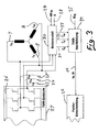
Fig.1 schematisch ein Diagramm des erfindungsgemäßen Verfahrens,1 shows schematically a diagram of the method according to the invention,
Fig.2 eine Ausschnitt des erfindungsgemäßen Verfahrens bezüglich der Fehlerentscheidung, und2 shows a detail of the method according to the invention with respect to the error decision, and
Fig.3 schematisch eine Variante des erfindungsgemäßen Verfahrens mit einer Überwachung auf der Basis von Phasenspannungen des Elektromotors.3 shows schematically a variant of the method according to the invention with a monitoring based on phase voltages of the electric motor.
Das in Fig.1 dargestellte Diagramm zeigt das erfindungsgemäße Verfahren der Fehlererkennung am Beispiel elektronisch kommutierten, dreiphasigen, permanenterregten Synchronmotors SM 1. Der Synchronmotors 1 weist einen Transistorwechselrichter TWR 2, auf, der eine geeignete Bestromung der Ständerwicklung ermittelt und über Leistungstreiber die Motorphasenströme iu 7, iv 8, iw 9 einregelt.The diagram shown in Figure 1 shows the inventive method of error detection using the example of electronically commutated, three-phase, permanent magnet
Die Vorgabe eines Soll-Drehmoments erfolgt indirekt über die Vorgabe eines drehmomentbildenden Stromes iq_soll 3 und eines feldschwächenden Stroms id_soll 4.The specification of a desired torque takes place indirectly via the specification of a torque-generating
Nach der Erfindung wird der Motor 1 inklusive des Transistorwechselrichters 2 insgesamt überwacht.According to the invention, the
Einer Überwachungseinheit 5 werden hierzu der angeforderte Sollwert des drehmomentbildenden Stromes iq_soll 6, Informationen über die Motorphasenströme iu 10, iv 11, iw 12 übermittelt.For this purpose, the requested nominal value of the torque-forming
Mittels der Überwachungseinheit 5,17 wird auf Grundlage der Motorphasenströme iu 10, iv 11, iw 12 und eines ermittelten, mechanischen Rotorlagewinkels εR 13 ein Schätzwert für den drehmomentbildenden Strom iq_th 14 ermittelt. Dies erfolgt vorzugsweise mittels einer modellbasierten Nachbildung des Transistorwechselrichters 2.By means of the
Der geschätzte Wert gibt indirekt auch das theoretisch an einer Motorwelle bzw. Antriebswelle 15 anliegende Drehmoment 16 an.The estimated value indirectly also indicates the
Der geschätzte Wert iq_th wird unter Berücksichtigung der Dynamik des Stromregelkreises mittels einer Fehlererkennungseinheit 17 mit dem Sollwert des drehmomentbildenden Stromes iq_soll verglichen. Bei Vorliegen einer signifikanten Abweichung zwischen iq_th und iq_soll wird eine Alarmmeldung ausgegeben 18. Zur Abdeckung von Fehlern in den Statorwicklungen und der Strommess-Sensorik wird zusätzlich noch überprüft, ob die Stromsumme des in Sternschaltung betriebenen Motors null ergibt:The estimated value iq_th is calculated taking into account the dynamics of the current control loop by means of an
![]()
![]()
Die Berücksichtigung der Dynamik der Motorstromregelung kann in klassischer Weise durch Beobachterstrukturen oder Paritätsmodelle geschehen.The consideration of the dynamics of the motor current control can be done in a classical way by observer structures or parity models.
Für bestimmte Anwendungsfälle wird diese nur durch Hinzufügen einer Latenzzeit vor einer Alarmmeldung berücksichtigt. Dies ist in der Fig.2 dargestellt.For certain applications, this is only taken into account by adding a latency period before an alarm message. This is shown in FIG.
Fig.2 zeigt eine Ausführung einer Entscheidungsstruktur zum Erkennen eines Fehlers 17. Aus den beiden Eingangsgrößen iq_soll 6 und iq_th 14 wird die Differenz gebildet 19. Der Betrag der Differenz wird mit einem Schwellwert s verglichen 20. Der Schwellwert kann auch nach weiteren Größen veränderbar sein (adaptiver Schwellwert). Bei blockkommutierten Motoren werden gegenüber sinuskommutierten Motoren höhere Schwellwerte festgelegt. Wird im Schritt 20 eine signifikante Abweichung zwischen dem Betrag der Differenz und dem Schwellwert erkannt, dann wird ein Timer 21 gestartet. Bei Verschwinden der signifikanten Abweichungen wird der Timer 21 wieder bis auf den Wert Null dekrementiert. Bei Überschreiten eines vorgegebenen Zählerstandes wird ausgegeben 22.FIG. 2 shows an embodiment of a decision structure for detecting an
Durch dieses Verfahren kann eine möglichst schnelle Fehlererkennung von "schwerwiegenden" Fehlern realisiert werden. Der genaue Fehlerort und die Ursache ist für diese Anwendungen weniger entscheidend. Damit ist das Verfahren der Erfindung zunächst besonders für eine schnelle Fehlererkennung der zuvor umschriebenen drei Fehlerklassen geeignet, wobei nur deren Auftreten angezeigt wird. Erweiterungen, die darüber hinaus auch Aussagen über den Fehlerort und die Fehlerursache erlauben, sind aber denkbar und können in das Verfahren integriert werden.By this method the fastest possible error detection of "serious" errors can be realized. The exact location and cause is less critical to these applications. This is the procedure The invention initially particularly suitable for rapid error detection of the previously circumscribed three error classes, only their occurrence is displayed. Extensions, which also allow statements about the location of the error and the cause of the error, are however conceivable and can be integrated into the method.
Der betroffene Aktuator, z. B. der die Antriebswelle 15 antreibende Motor 1, wird bei erkanntem Fehler in Form einer "kollektiven" Fehlerbehandlung abgeschaltet (failsilent Verhalten) und redundante Systeme aktiviert.The affected actuator, z. B. the
Eine detaillierte Fehlerdiagnose erfolgt dann im Rahmen einer eingeleiteten Reparatur oder nach der Abschaltung selbsttätig in hierzu geeigneten Betriebszuständen durch entsprechende Algorithmen und Ablaufszenarien.A detailed fault diagnosis is then carried out as part of an initiated repair or after the shutdown automatically in suitable operating conditions by appropriate algorithms and process scenarios.
Der besondere Vorteil der Erfindung ist es, dass durch das Prinzip des Über-Alles-Tests in Verbindung mit der Stromsummenprüfung alle zuvor erwähnten, durch Ausfälle der Regeleinheit 2 bedingten Fehlerklassen (selbsttätige Bewegung, elektrisches Festklemmen, Ausfall des Motors) erkannt werden können, unabhängig davon, wo der ursächliche Fehler lokalisiert ist, z.B. eine fehlerhafte Sollwertübergabe, eine defekte Rotorpositionssensorik oder eine defekte Endstufe zur Ansteuerung des Motors 1.The particular advantage of the invention is that by the principle of over-all testing in conjunction with the current sum test all previously mentioned, caused by failures of the
Ein bürstenloser Motor 1 kann auch von Fehlern beeinträchtigt werden, die zwar eine Abweichung von einer normalen Funktion darstellen, aber die Drehmomenterzeugung des Motors 1 nicht oder nur minimal beeinträchtigen, wie z. B. Fehler die eine Reduzierung eines Verstärkungsfaktors in der Regeleinheit 2 bewirken. Solange durch das Verfahren keine Fehlermeldung erzeugt wird, ist eine Abschaltung des Aktuators 1 nicht erforderlich. Das abgegebene Drehmoment stimmt im wesentlichen mit der Sollwertvorgabe überein. Die Fehler werden in diesen Fällen durch die Regeleinheit 2 ausgeregelt. Diese Fehler werden so durch die "Robustheit" des Regelkreises abgefangen und erfordern keine Gegenmaßnahmen.A
Die Dynamik der Fehlererkennung liegt in der Größenordnung der Zeitkonstante der Motorstromregelung und damit in der Regel « 10 ms. Es ist somit schneller als Verfahren, die auf die Auswertung der Motorstrominformation verzichten und statt dessen rein mechanische Aktuatorgrößen, wie Rotorbeschleunigung, Rotorgeschwindigkeit oder Rotorlage, verwenden.The dynamics of the error detection is in the order of magnitude of the time constant of the motor current control and thus usually «10 ms. It is thus faster than methods that dispense with the evaluation of the motor current information and instead use purely mechanical actuator sizes, such as rotor acceleration, rotor speed or rotor position.
Das Fehlererkennungsverfahren ist weiterhin universell bei elektronisch kommutierten Motoren mit Lagesensorik einsetzbar, unabhängig vom umgesetzten Prinzip der Motorregelung und demnach insbesondere sowohl für polradorientierte, als auch statororientierte Regelung einsetzbar.The error detection method is also universally applicable to electronically commutated motors with position sensors, regardless of the implemented principle of motor control and therefore especially for both pole-oriented, and stator-oriented control.
Im Gegensatz zu Verfahren, bei denen nur der Richtungssinn des Drehmomentes ausgewertet wird, werden hier als Vorteil auch Fehler erkannt, die eine Verstärkung oder Verringerung des Drehmoments zur Folge haben. So können auch Fehler, die Momentenwelligkeiten am Antriebsmoment hervorrufen, erkannt werden. Dies ist vor allem bei Systemen mit einer taktilen Schnittstelle zum Bediener, z. B. elektrische Servolenksysteme oder Steer-by-Wire-Systeme mit Handmomentensteller, von großer Bedeutung.In contrast to methods in which only the sense of direction of the torque is evaluated, errors are also recognized as an advantage here, which result in an increase or decrease of the torque. Thus, errors that cause torque ripples at the drive torque can be detected. This is especially true for systems with a tactile interface to the operator, eg. As electric power steering systems or steer-by-wire systems with manual torque controller, of great importance.
Im Gegensatz zu anderen denkbaren Verfahren zur Motorfehlererkennung liefert diese Erfindung durch Schätzung des Motordrehmoments schließlich die wichtige Aussage, ob und wie der Motor seine eigentliche Funktion (Drehmomenterzeugung) noch erfüllt, und ob von einer von evtl. parallel arbeitenden Fehlererkennungsverfahren empfohlenen Abschaltung abgesehen werden kann. Dies erhöht die Verfügbarkeit des Gesamtsystems.In contrast to other conceivable methods for engine error detection, this invention finally provides by estimating the engine torque the important statement as to whether and how the engine still fulfills its actual function (torque generation), and whether from one of possibly parallel working fault detection method recommended shutdown can be disregarded. This increases the availability of the entire system.
Fig.3 zeigt ein modifiziertes Verfahren. Anstelle der aufwendig zu bestimmenden, durch die Endstufe 26 der Motor-Regeleinheit 2 einsteuerbaren Phasenströme iu 7, iv 8, iw 9 können diese auf Basis der entsprechenden einfach zu bestimmenden Strangspannungen oder Phasenspannungen uu 23, uv 24, uw 25 unter Berücksichtigung der drehzahlproportionalen induzierten Gegenspannung geschätzt und so dem Algorithmus zur Verfügung gestellt werden.3 shows a modified method. Instead of the expensive to be determined, einsteuerbaren by the
Wegen der Zunahme der Unsicherheiten, z. B. durch eine nichtlineare, temperaturabhängige Motorkonstante, eine temperaturabhängige Wicklungswiderstände und einen hohen Wechselanteil der Strangspannungen, werden höhere Schwellwerte mit dem Ergebnis längerer Fehlererkennungszeiten eingestellt. Darüber hinaus werden die Wicklungs- und/oder Motortemperatur ϑ 28 und die Rotorgeschwindigkeit ωR 29 erfasst und ausgewertet. Aus den Eingangsgrößen werden auf Grundlage eines Motormodells 30 Motorphasenströme iu, th 31, iv, th 32, iw, th 33 geschätzt und als Eingangsgrößen einer Überwachungseinheit 34 zugeführt. Auf Grundlage einer modellbasierten Nachbildung der Regeleinheit 27 wird darin der Schätzwert für den drehmomentbildenden Strom iq_th ermittelt, wobei als weitere Eingangsgröße der ermittelte, mechanische Rotorlagewinkels εR 34 dient. Der Schätzwert für den drehmomentbildenden Strom iq_th wird dann der Fehlererkennung 36 zugeführt.Because of the increase in uncertainties, eg. B. by a non-linear, temperature-dependent motor constant, a temperature-dependent winding resistances and a high alternating component of the strand voltages, higher thresholds are set with the result of longer error detection times. In addition, the winding and / or
Ein Vorteil bei diesem modifizierten Verfahren ist neben dem Verzicht auf eine Strommessung, dass zusätzlich zu Fehlern in der Regeleinheit auch Windungsschlüsse im Stator erkannt werden können.An advantage of this modified method, in addition to the absence of a current measurement, that in addition to errors in the control unit and Windungsschlüsse can be detected in the stator.
Bei den zuvor beschriebenen Ausführungsbeispielen wird das Modell nicht mit dem Sollwert des drehmomentbildenden Stroms iq_soll versorgt, sondern dieser wird auf Basis der Phasenströme (Fig.1) bzw. Phasenspannungen (Fig.3) geschätzt, was durch dessen hohe Aussagekraft und Interpretierbarkeit vorteilhaft ist.In the embodiments described above, the model is not supplied with the desired value of the torque-generating current iq_soll, but this is estimated based on the phase currents (Figure 1) and phase voltages (Figure 3), which is advantageous by its high significance and interpretability.
Es sind ebenfalls Verfahren denkbar, die den Zusammenhang zwischen angefordertem Drehmoment eines bürstenlosen Motors und der Stromaufnahme der Endstufe für eine Fehlererkennung ausnutzen. Eine hohe Stromaufnahme der Endstufe ohne Vorliegen eines entsprechend hohen Wertes für iq_soll ist dann ein Hinweis für einen Fehler. Ein großer Wert für iq_soll ohne entsprechende Stromaufnahme der Endstufe ist ebenfalls als nicht plausibel einzustufen und damit auch ein Hinweis für einen Fehler. Aufgrund von größeren Unsicherheiten werden die Entscheidungsschwellen zur Fehlererkennung nochmals angehoben mit dem Ergebnis, dass leichtere Fehler unerkannt bleiben. Nachteilig ist, dass keine Aussage über den Richtungssinn des Drehmoments möglich ist. Schwere Fehler, die eine Invertierung des Vorzeichens des Sollwertes hervorrufen, bleiben unerkannt. Aufgrund des relativ einfachen Verfahrens wird es für bestimmte Anwendungsfälle als zusätzliches Fehlererkennungsverfahren bei besonders sicherheitsrelevanten Systemen vorgesehen.There are also conceivable methods that exploit the relationship between the requested torque of a brushless motor and the power consumption of the power amplifier for fault detection. A high current consumption of the output stage without a correspondingly high value for iq_soll is then an indication of an error. A large value for iq_soll without corresponding current consumption of the output stage is also to be classified as not plausible and thus also an indication of an error. Due to greater uncertainties, the decision thresholds for error detection are raised again with the result that lighter errors remain undetected. The disadvantage is that no statement about the sense of direction of the torque is possible. Severe errors that cause an inversion of the sign of the setpoint remain undetected. Due to the relatively simple method, it is intended for certain applications as an additional error detection method in particularly safety-relevant systems.
Claims (9)
- Method for error detection of a brushless electric motor (1), wherein at least one first motor parameter (iu, iv, iw) is measured or determined, and a second, estimated motor parameter (iq-th) is estimated on the basis of the first motor parameter (iu, iv, iw),
characterized in that for the error detection of the electric motor (1) inclusive commutation electronics (2), the second, estimated motor parameter (iq-th) is compared to a nominal current (iqnominal, 6) producing a motor torque, and an error in the electric motor (1) can be found out according to the comparison. - Method as claimed in claim 1,
characterized in that the second, estimated motor parameter (iq_th) is estimated on the basis of a model (5). - Method as claimed in claim 1 or 2,
characterized in that an estimated current (iq-th) producing a motor torque or a quantity derived therefrom is estimated as a second, estimated motor parameter and compared with the nominal current (iqnominal, 6) producing a motor torque or a quantity derived therefrom as a second motor parameter. - Method as claimed in claim 3,
characterized in that the estimated current (iq-th) producing the motor torque or the quantity derived therefrom is estimated on the basis of at least one phase motor current (iu, iv, iw), preferably three-phase motor currents, and a rotor position (εR) or phase relation of the electric motor (1). - Method as claimed in claim 4,
characterized in that the absolute rotor position (εR) or phase relation relative to a stator of the electric motor (1) is defined by measuring the respective actual phase relation variation of the rotor relative to the stator and determining the absolute phase relation therefrom. - Method as claimed in claim 4 or 5,
characterized in that the phase currents (iu, iv, iw) are estimated on the basis of phase voltages in consideration of induced countervoltages proportional to rotational speed. - Method as claimed in any one of claims 3 to 6,
characterized in that the temperature (vi) of the electric motor (1) and/or the windings of the electric motor is measured and also taken into consideration in the estimation of the estimated currents. - Method as claimed in claim 1,
characterized in that an error is detected according to a comparison between the requested torque of the brushless electric motor and the current consumption of an end stage that actuates the electric motor. - Method as claimed in any one or more of the preceding claims,
characterized in that there is detection of a first class of errors that causes undesirable motion of the motor, a second class of errors that causes electronic clamping of the rotor so that rotation is no longer possible or highly impaired, and a third class of errors that prevents the motor from developing torque as a result.
Applications Claiming Priority (5)
| Application Number | Priority Date | Filing Date | Title |
|---|---|---|---|
| DE10206099 | 2002-02-13 | ||
| DE10206099 | 2002-02-13 | ||
| DE10254752A DE10254752A1 (en) | 2002-02-13 | 2002-11-23 | Fault detection method for electric motors |
| DE10254752 | 2002-11-23 | ||
| PCT/EP2003/000302 WO2003069768A1 (en) | 2002-02-13 | 2003-01-15 | Method for the detection of abnormalities of electric motors |
Publications (2)
| Publication Number | Publication Date |
|---|---|
| EP1479157A1 EP1479157A1 (en) | 2004-11-24 |
| EP1479157B1 true EP1479157B1 (en) | 2006-12-06 |
Family
ID=27735673
Family Applications (1)
| Application Number | Title | Priority Date | Filing Date |
|---|---|---|---|
| EP03739438A Expired - Lifetime EP1479157B1 (en) | 2002-02-13 | 2003-01-15 | Method for the detection of abnormalities of electric motors |
Country Status (5)
| Country | Link |
|---|---|
| US (1) | US7385365B2 (en) |
| EP (1) | EP1479157B1 (en) |
| JP (1) | JP2005518178A (en) |
| DE (1) | DE50305900D1 (en) |
| WO (1) | WO2003069768A1 (en) |
Cited By (1)
| Publication number | Priority date | Publication date | Assignee | Title |
|---|---|---|---|---|
| WO2014019882A1 (en) | 2012-08-02 | 2014-02-06 | Continental Automotive Gmbh | Method for detecting a fault in a motor arrangement with an electrical machine and motor control unit |
Families Citing this family (24)
| Publication number | Priority date | Publication date | Assignee | Title |
|---|---|---|---|---|
| DE102005044629A1 (en) * | 2005-09-19 | 2007-03-22 | Infineon Technologies Ag | Electric motor controlling device for e.g. motor vehicle, has monitoring unit outputting error signals during malfunction of sensor, and safety unit producing alternative motor control signals for controlling motor in quiescent state |
| JP4774975B2 (en) * | 2005-12-15 | 2011-09-21 | トヨタ自動車株式会社 | Electric motor control device |
| GB0526276D0 (en) * | 2005-12-23 | 2006-02-01 | Trw Ltd | Electric motor control |
| DE102006006032A1 (en) * | 2006-02-09 | 2007-08-23 | Siemens Ag | Method and device for operating a synchronous machine |
| SE532537C2 (en) * | 2007-06-12 | 2010-02-16 | Subsee Ab | Device and method for off-line testing of an electric motor |
| CN102004224B (en) * | 2009-08-31 | 2012-12-12 | 比亚迪股份有限公司 | Three-phase motor phase failure detection system and detection method thereof |
| DE102010000991A1 (en) * | 2010-01-19 | 2011-07-21 | ZF Friedrichshafen AG, 88046 | Phase cutoff detection method for e.g. permanently excited synchronous machine of drive device, involves examining longitudinal current to find whether actual phase currents correspond to target current according to current level |
| FR2981474B1 (en) * | 2011-10-17 | 2013-12-27 | Alstom Technology Ltd | METHOD FOR PREVENTIVELY DETECTING FAILURE OF AN APPARATUS, COMPUTER PROGRAM, INSTALLATION AND MODULE FOR PREVENTIVELY DETECTING FAILURE OF AN APPARATUS |
| JP5296942B1 (en) | 2012-07-20 | 2013-09-25 | 三菱電機株式会社 | Control device |
| US9071110B2 (en) | 2012-10-16 | 2015-06-30 | Eht International Inc. | Abnormality detection method and apparatus |
| JP5607698B2 (en) * | 2012-10-18 | 2014-10-15 | ファナック株式会社 | Temperature estimation device for estimating the temperature of an electric motor |
| DE102014210653A1 (en) * | 2014-06-04 | 2015-12-17 | Conti Temic Microelectronic Gmbh | Device for controlling and / or monitoring a brushless DC motor |
| JP6506844B2 (en) * | 2014-12-16 | 2019-04-24 | ビーワイディー カンパニー リミテッドByd Company Limited | Electric vehicle, active safety control system of electric vehicle, control method of active safety control system of electric vehicle, and motor controller |
| DE112017000239B4 (en) * | 2016-01-13 | 2022-08-11 | Hitachi Astemo, Ltd. | steering device |
| US10928814B2 (en) | 2017-02-24 | 2021-02-23 | General Electric Technology Gmbh | Autonomous procedure for monitoring and diagnostics of machine based on electrical signature analysis |
| US10678668B1 (en) * | 2017-06-14 | 2020-06-09 | Fischer Block, Inc. | Using steady-state changes to discern the operating performance of an individual machine operating on a commonly supplied electrical network connected to multiple machines |
| US10403116B2 (en) | 2017-06-20 | 2019-09-03 | General Electric Company | Electrical signature analysis of electrical rotating machines |
| DE102018216334A1 (en) | 2018-02-08 | 2019-08-08 | Robert Bosch Gmbh | Method and device for external monitoring of a power converter |
| US20220194542A1 (en) | 2020-12-22 | 2022-06-23 | Brunswick Corporation | Electric marine propulsion systems and methods of control |
| US20230053671A1 (en) | 2021-08-17 | 2023-02-23 | Brunswick Corporation | Electric marine propulsion system and control method with emergency depletion mode |
| US20230054361A1 (en) | 2021-08-17 | 2023-02-23 | Brunswick Corporation | Electric marine propulsion system and control method |
| US20230219676A1 (en) | 2022-01-12 | 2023-07-13 | Brunswick Corporation | Electric marine propulsion system and control method |
| US20230219675A1 (en) | 2022-01-12 | 2023-07-13 | Brunswick Corporation | Electric marine propulsion system and control method |
| US20230294521A1 (en) | 2022-03-15 | 2023-09-21 | Brunswick Corporation | Electric marine propulsion system and control method |
Family Cites Families (20)
| Publication number | Priority date | Publication date | Assignee | Title |
|---|---|---|---|---|
| JPH0650954B2 (en) | 1987-05-26 | 1994-06-29 | 株式会社東芝 | Commutatorless motor controller |
| JPH02219498A (en) * | 1989-02-16 | 1990-09-03 | Toyota Central Res & Dev Lab Inc | Current controller of inverter |
| US5389825A (en) * | 1991-04-24 | 1995-02-14 | Aisin Aw Co., Ltd. | System of controlling changeover of an electric power source for an electric motor vehicle |
| DE4343627A1 (en) * | 1993-12-21 | 1995-06-22 | Abb Patent Gmbh | Method for controlling the amount of flow and torque of an induction machine |
| DE4437793C2 (en) | 1994-10-21 | 1998-05-07 | Agie Ag Ind Elektronik | Method and device for controlling an electric motor |
| JP3362537B2 (en) * | 1994-12-27 | 2003-01-07 | 日産自動車株式会社 | Fail-safe control of drive motor for electric vehicles |
| DE19514897A1 (en) * | 1995-04-22 | 1996-10-24 | Abb Patent Gmbh | Method for a three-phase machine operated according to direct self-regulation |
| JP3709239B2 (en) * | 1996-04-26 | 2005-10-26 | ファナック株式会社 | Magnetic saturation correction method for AC servo motor |
| KR19980015274A (en) * | 1996-08-20 | 1998-05-25 | 김광호 | Motor abnormal condition detection device and abnormal condition detection method |
| US5729113A (en) * | 1997-01-21 | 1998-03-17 | General Electric Company | Sensorless rotor velocity estimation for induction motors |
| DE19709296A1 (en) * | 1997-03-06 | 1998-09-24 | Siemens Ag | Method and device for identifying the system parameters stator resistance and rotor resistance of an encoderless, field-oriented induction machine |
| GB9810101D0 (en) * | 1998-05-13 | 1998-07-08 | Lucas Ind Plc | Improvements relating to electric motors |
| DE19826131A1 (en) * | 1998-06-12 | 1999-12-16 | Bosch Gmbh Robert | Electrical braking system for a motor vehicle has optimised operating reliability and availability |
| JP3712876B2 (en) * | 1998-12-01 | 2005-11-02 | 三菱電機株式会社 | Electric power steering control device |
| JP4147706B2 (en) * | 1998-12-18 | 2008-09-10 | トヨタ自動車株式会社 | Electrical angle detection device, detection method, and motor control device |
| US6462491B1 (en) * | 1999-01-27 | 2002-10-08 | Matsushita Electric Industrial Co., Ltd. | Position sensorless motor control apparatus |
| EP1218754A4 (en) * | 1999-09-16 | 2004-09-22 | Delphi Tech Inc | Torque current comparison for current reasonableness diagnostics in a permanent magnet electric machine |
| DE19958529A1 (en) | 1999-12-04 | 2001-06-07 | Daimler Chrysler Ag | Method to determine motor current through motor; involves defining parameter comparison with motor current as function of parameters motor characteristic data, such as rpm and operation voltage |
| JP3681318B2 (en) * | 2000-02-28 | 2005-08-10 | 株式会社日立製作所 | Synchronous motor control device and vehicle using the same |
| JP3411878B2 (en) * | 2000-03-06 | 2003-06-03 | 株式会社日立製作所 | Method for estimating rotor position of synchronous motor, control method without position sensor, and control device |
-
2003
- 2003-01-15 JP JP2003568767A patent/JP2005518178A/en active Pending
- 2003-01-15 US US10/503,676 patent/US7385365B2/en not_active Expired - Fee Related
- 2003-01-15 WO PCT/EP2003/000302 patent/WO2003069768A1/en active IP Right Grant
- 2003-01-15 DE DE50305900T patent/DE50305900D1/en not_active Expired - Lifetime
- 2003-01-15 EP EP03739438A patent/EP1479157B1/en not_active Expired - Lifetime
Cited By (3)
| Publication number | Priority date | Publication date | Assignee | Title |
|---|---|---|---|---|
| WO2014019882A1 (en) | 2012-08-02 | 2014-02-06 | Continental Automotive Gmbh | Method for detecting a fault in a motor arrangement with an electrical machine and motor control unit |
| DE102012213709A1 (en) | 2012-08-02 | 2014-02-06 | Continental Automotive Gmbh | A method for detecting a fault of a motor assembly with an electric machine and engine control unit |
| US10027263B2 (en) | 2012-08-02 | 2018-07-17 | Continental Automotive Gmbh | Method for detecting a fault in a motor arrangement with an electrical machine and motor control unit |
Also Published As
| Publication number | Publication date |
|---|---|
| DE50305900D1 (en) | 2007-01-18 |
| WO2003069768A1 (en) | 2003-08-21 |
| EP1479157A1 (en) | 2004-11-24 |
| JP2005518178A (en) | 2005-06-16 |
| US20050092105A1 (en) | 2005-05-05 |
| US7385365B2 (en) | 2008-06-10 |
Similar Documents
| Publication | Publication Date | Title |
|---|---|---|
| EP1479157B1 (en) | Method for the detection of abnormalities of electric motors | |
| DE102018202052B4 (en) | rotation detection device | |
| EP2499737B1 (en) | Method for checking the plausibility of the torque of an electrical machine and machine controller for controlling an electrical machine and for carrying out the method | |
| DE102013008191B4 (en) | Magnetic pole position determination device for determining a position of the magnetic pole of the rotor in a permanent magnet synchronous motor | |
| DE102011051233A1 (en) | Motor drive control apparatus and method and power steering system using same | |
| DE102014225149A1 (en) | Error determination method for an engine system | |
| WO2012163585A2 (en) | Method and apparatus for angle estimation in a synchronous machine | |
| DE102011085896A1 (en) | Motor control device | |
| DE102012107084A1 (en) | Motor controller | |
| DE10220887B4 (en) | Monitoring system for a microcomputer, which calculates the rotation angle of a rotating device | |
| DE112016003040T5 (en) | Drive device for three-phase synchronous motor | |
| DE102015226382A1 (en) | Method and arrangement for monitoring a PSM machine | |
| DE102011001278A1 (en) | Method and apparatus for controlling a stop of rotation of an electric motor for use in machines for manufacturing | |
| EP2446528B1 (en) | Method and device for compensating load influences in permanently excited motors | |
| DE102016224178A1 (en) | Control of a six-phase PSM | |
| DE102019129404A1 (en) | CONTROLLING A PERMANENT MAGNETIC SYNCHRONOUS MOTOR DRIVE IN THE EVALUATION ERROR | |
| DE19960289A1 (en) | Fault detection system for brushless electric motor, e.g. for power-steering system; has fault detector constructed to measure fault by detecting excitation in electromagnet coil of either rotor or stator | |
| EP1699676B1 (en) | Method for reducing the speed of an electric motor and electric drive | |
| EP3348434A1 (en) | Method for monitoring a drive system, in particular a drive train of an electric vehicle, and control device operating according to this method | |
| EP2998753B1 (en) | Monitoring device for an electric machine, control device and method | |
| DE112021006863T5 (en) | Vehicle steering control device, steer-by-wire system, and method for controlling a steer-by-wire system | |
| DE10254752A1 (en) | Fault detection method for electric motors | |
| DE102021131083A1 (en) | DIAGNOSIS OF AN INPUT POWER CONDITION FOR AN ELECTRIC POWER STEERING | |
| DE102014106716B4 (en) | Rotary electric machine control device having an abnormality detection function | |
| EP3014756B1 (en) | Method for detecting an incorrect angular position of an electric motor |
Legal Events
| Date | Code | Title | Description |
|---|---|---|---|
| PUAI | Public reference made under article 153(3) epc to a published international application that has entered the european phase |
Free format text: ORIGINAL CODE: 0009012 |
|
| 17P | Request for examination filed |
Effective date: 20040913 |
|
| AK | Designated contracting states |
Kind code of ref document: A1 Designated state(s): AT BE CH CY DE DK ES FI FR GB GR HU IE IT LI LU MC NL PT SE SI |
|
| 17Q | First examination report despatched |
Effective date: 20050119 |
|
| GRAP | Despatch of communication of intention to grant a patent |
Free format text: ORIGINAL CODE: EPIDOSNIGR1 |
|
| RIC1 | Information provided on ipc code assigned before grant |
Ipc: H02P 6/12 20060101AFI20060410BHEP Ipc: H02P 21/00 20060101ALI20060410BHEP Ipc: H02P 6/16 20060101ALI20060410BHEP |
|
| GRAS | Grant fee paid |
Free format text: ORIGINAL CODE: EPIDOSNIGR3 |
|
| GRAA | (expected) grant |
Free format text: ORIGINAL CODE: 0009210 |
|
| AK | Designated contracting states |
Kind code of ref document: B1 Designated state(s): DE FR IT |
|
| PG25 | Lapsed in a contracting state [announced via postgrant information from national office to epo] |
Ref country code: IT Free format text: LAPSE BECAUSE OF FAILURE TO SUBMIT A TRANSLATION OF THE DESCRIPTION OR TO PAY THE FEE WITHIN THE PRESCRIBED TIME-LIMIT;WARNING: LAPSES OF ITALIAN PATENTS WITH EFFECTIVE DATE BEFORE 2007 MAY HAVE OCCURRED AT ANY TIME BEFORE 2007. THE CORRECT EFFECTIVE DATE MAY BE DIFFERENT FROM THE ONE RECORDED. Effective date: 20061206 |
|
| REF | Corresponds to: |
Ref document number: 50305900 Country of ref document: DE Date of ref document: 20070118 Kind code of ref document: P |
|
| ET | Fr: translation filed | ||
| PLBE | No opposition filed within time limit |
Free format text: ORIGINAL CODE: 0009261 |
|
| STAA | Information on the status of an ep patent application or granted ep patent |
Free format text: STATUS: NO OPPOSITION FILED WITHIN TIME LIMIT |
|
| 26N | No opposition filed |
Effective date: 20070907 |
|
| REG | Reference to a national code |
Ref country code: FR Ref legal event code: PLFP Year of fee payment: 13 |
|
| PGFP | Annual fee paid to national office [announced via postgrant information from national office to epo] |
Ref country code: IT Payment date: 20150128 Year of fee payment: 13 Ref country code: DE Payment date: 20150131 Year of fee payment: 13 |
|
| PGFP | Annual fee paid to national office [announced via postgrant information from national office to epo] |
Ref country code: FR Payment date: 20150122 Year of fee payment: 13 |
|
| REG | Reference to a national code |
Ref country code: DE Ref legal event code: R119 Ref document number: 50305900 Country of ref document: DE |
|
| REG | Reference to a national code |
Ref country code: FR Ref legal event code: ST Effective date: 20160930 |
|
| PG25 | Lapsed in a contracting state [announced via postgrant information from national office to epo] |
Ref country code: DE Free format text: LAPSE BECAUSE OF NON-PAYMENT OF DUE FEES Effective date: 20160802 |
|
| PG25 | Lapsed in a contracting state [announced via postgrant information from national office to epo] |
Ref country code: FR Free format text: LAPSE BECAUSE OF NON-PAYMENT OF DUE FEES Effective date: 20160201 |
|
| PG25 | Lapsed in a contracting state [announced via postgrant information from national office to epo] |
Ref country code: IT Free format text: LAPSE BECAUSE OF NON-PAYMENT OF DUE FEES Effective date: 20160115 |