EP1128172B1 - Capteur de pression - Google Patents
Capteur de pression Download PDFInfo
- Publication number
- EP1128172B1 EP1128172B1 EP00103681A EP00103681A EP1128172B1 EP 1128172 B1 EP1128172 B1 EP 1128172B1 EP 00103681 A EP00103681 A EP 00103681A EP 00103681 A EP00103681 A EP 00103681A EP 1128172 B1 EP1128172 B1 EP 1128172B1
- Authority
- EP
- European Patent Office
- Prior art keywords
- pressure
- chamber
- measuring
- diaphragm
- measuring cell
- Prior art date
- Legal status (The legal status is an assumption and is not a legal conclusion. Google has not performed a legal analysis and makes no representation as to the accuracy of the status listed.)
- Expired - Lifetime
Links
Images
Classifications
-
- G—PHYSICS
- G01—MEASURING; TESTING
- G01L—MEASURING FORCE, STRESS, TORQUE, WORK, MECHANICAL POWER, MECHANICAL EFFICIENCY, OR FLUID PRESSURE
- G01L9/00—Measuring steady of quasi-steady pressure of fluid or fluent solid material by electric or magnetic pressure-sensitive elements; Transmitting or indicating the displacement of mechanical pressure-sensitive elements, used to measure the steady or quasi-steady pressure of a fluid or fluent solid material, by electric or magnetic means
- G01L9/0041—Transmitting or indicating the displacement of flexible diaphragms
- G01L9/0072—Transmitting or indicating the displacement of flexible diaphragms using variations in capacitance
- G01L9/0075—Transmitting or indicating the displacement of flexible diaphragms using variations in capacitance using a ceramic diaphragm, e.g. alumina, fused quartz, glass
Definitions
- the invention relates to a pressure sensor.
- a pressure to be measured becomes absolute, i. detected as a pressure difference to a vacuum.
- a pressure to be measured in the form of a pressure difference from a reference pressure, e.g. a pressure prevailing where the sensor is located. For most applications, this is atmospheric pressure at the jobsite.
- a pressure to be measured relative to a fixed reference pressure the vacuum pressure
- a pressure to be measured relative to a variable reference pressure e.g. the ambient pressure detected.
- ceramic pressure measuring cells have a measurement accuracy that is stable over a very long time.
- One reason for this is solid ionic bonding of ceramics, which makes the material very durable and, compared to other materials, e.g. Metals, practically not aging.
- ceramic pressure sensors have a rougher surface compared to a metal and are periodically replaced by a generally non-replaceable gasket made of an organic material, e.g. an elastomer, pressure-tight clamped in a housing, which is then to be attached via a process connection to a measuring location.
- the pressure sensors have as few seals as possible. Seals are made of organic materials and should therefore preferably be interchangeable for hygienic reasons. Ideally, there is only a single seal to seal the process connection. This, hereinafter referred to as process seal seal, in contrast to a sensor associated with the seal itself at any time easily, esp. Without effect on the accuracy of the pressure sensor to be replaced.
- the object is achieved by the pressure sensor according to claim 1.
- the measuring cell is fixed in a housing without tension by being seated in the axial direction on a tube, via which the ceramic measuring cell is connected to the pressure transmitter.
- the measuring cell to a measuring diaphragm, which is an interior of the measuring cell in a divided into a first and a second chamber.
- the first chamber is connected via a tube to the diaphragm seal, the first chamber, the tube and the diaphragm seal are filled with a liquid, the liquid transmits a pressure acting on the separation membrane pressure on the measuring diaphragm, in the second chamber, a reference pressure acts on the measuring diaphragm a, and the pressure sensor comprises an electromechanical transducer for detecting a pressure and the reference pressure dependent deflection of the diaphragm and for converting them into an electrical output signal.
- the reference pressure is a reference pressure prevailing in the environment and the second chamber has an opening through which the reference pressure is introduced into the second chamber, or the second chamber is hermetically sealed and the reference pressure is an absolute pressure prevailing in the second chamber.
- the measuring cell is additionally enclosed in the radial direction in a holder.
- the holder has a body filling an intermediate space between the measuring cell and the housing made of an elastomer.
- Investigations have shown that in a conventional manner by means of an organic material, such as a seal made of an elastomer, pressure-tight clamped ceramic measuring cell diaphragm seals can not be used without very large losses in the accuracy of measurement. Temperature and / or pressure changes can lead to changes in position and / or shape of the seal, which are associated with a displacement of diaphragm seal fluid. In a diaphragm seal, only a small amount of the diaphragm seal fluid is displaced by a pressure change. If gasket-related volume shifts are of the same order of magnitude as pressure-related volume shifts, a meaningful measurement is no longer possible.
- sealing materials are plastics such as e.g. Polytetrafluoroethylene or Viton. These materials are not gas-tight. If a vacuum acts on the pressure sensor, air or gas can diffuse into the diaphragm seal fluid through the seal from a side of the pressure sensor facing away from the pressure transmitter. Air or gas in the
- Diaphragm seal seriously affects the accuracy of the pressure sensor.
- Another advantage is that, despite the use of a ceramic pressure measuring cell, apart from the process seal, only metallic materials come into contact with the medium whose pressure is to be measured.
- the pressure transmitter it is possible to freely select the metal touched by the medium within wide limits according to the mechanical and / or chemical properties of the medium.
- weld neck i. mounted on the container welded neck.
- the sealing takes place in weld-in sockets usually purely metallic, e.g. about sealing koni. In these cases, even the process seal is eliminated.
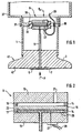
- Fig. 1 is a section through a pressure sensor according to the invention shown.
- the pressure sensor comprises a substantially cylindrical housing 1, in whose one end a diaphragm seal 3 is enclosed. It is welded into the housing 1.
- the pressure transmitter 3 has a chamber 5 filled with a liquid, which is closed by a separating membrane 7.
- a pressure P to be measured acts on the separation membrane 7, which in Fig. 1 indicated by an arrow.
- a ceramic measuring cell 9 is arranged, which is connected via a filled with the liquid tube 11 with the chamber 5 of the pressure transmitter 3.
- Fig. 2 It shows an enlarged view of the measuring cell 9. It comprises two cylindrical body 13 and a rimmed between the two bodies measuring diaphragm 15th
- the measuring cell 9 is a ceramic measuring cell, i. the main body 13 and the measuring diaphragm 15 are made of ceramic.
- the measuring diaphragm 15 is pressure-tight and gas-tight with each of the base body 1 at the edge facing the respective base body 13 by means of a joint 14.
- As the joining material e.g. an active hard solder.
- the measuring diaphragm 15 is pressure-sensitive, i. a pressure acting on them causes a deflection of the measuring diaphragm 15 from its rest position.
- the ceramic measuring cell 9 is connected to the diaphragm seal 3 exclusively with inorganic materials.
- joining or joining techniques such as soldering or welding are suitable.
- the first chamber 17 is connected via the tube 11 with the diaphragm seal 3.
- the tube 11 is welded, for example, to the diaphragm seal 3 and fixed to the base body 13 by a soldering. No gasket made of organic material is required.
- the first chamber 17 is just like the diaphragm seal 3 and the tube 11 filled with liquid.
- a pressure P acting on the separating membrane 7 is transmitted through the liquid to the measuring cell 9 in the first chamber 17.
- the liquid is as incompressible as possible and has the lowest possible coefficient of thermal expansion.
- commercially available silicone oils are suitable.
- the required filling amount is preferably to be kept low by the tube 11 has a small diameter and the pressure transmitter 3 in the chamber 5 has a membrane bed, which is modeled after the shape of the separation membrane 7 and is arranged at a small distance from the separation membrane 7.
- a flame arrester can be arranged in the tube 11 or the tube 11 itself can form a flame arrester due to its dimensions.
- the structure of such a flame arrester can be found in the national safety regulations and standards for explosion protection.
- the second chamber 19 an opening 21, here a base body 13 penetrating bore, through which a reference pressure is introduced into the second chamber 19.
- the reference pressure is a pressure prevailing in the pressure sensor reference pressure P R , here an ambient pressure. It is therefore a relative pressure sensor.
- a variable pressure e.g. be introduced into the second chamber 19 via a second in a similar manner to the pressure transmitter 3 connected to the pressure transmitter.
- the deflection of the measuring diaphragm is dependent on the difference between the two pressures acting on it.
- the pressure sensor according to the invention can of course also be designed as an absolute pressure sensor.
- the second chamber 19 is evacuated and hermetic sealed and the reference pressure is a prevailing in the second chamber 19 absolute pressure.
- the measuring cell 9 has an electromechanical transducer for detecting a dependent of the pressure P and the reference pressure deflection of the diaphragm 15 and for converting them into an electrical output signal.
- the electromechanical transducer comprises a capacitor which has a arranged in the first chamber 17 on the measuring diaphragm 15 measuring electrode 23 and the one of the measuring electrode 23 opposite on an inner wall of the first chamber 17 arranged on the base body 13 counter electrode 25.
- the capacitance of the capacitor depends on the distance of the measuring electrode 23 and the counter electrode 25 to each other and is thus a measure of the deflection of the measuring diaphragm 15th
- the measuring electrode 23 is electrically contacted by the joint 14 and outside of e.g. connected to ground.
- the counterelectrode 25 is electrically contacted by the base body 13 to the outside thereof and leads to an electronic circuit 27 arranged on the base body 13. Measuring electrode 23 and counter electrode 25 form a capacitor and the electronic circuit 27 forms the capacitance changes of the capacitor e.g. in a correspondingly changing electrical voltage.
- the output signal is available via connecting lines 29 for further processing and / or evaluation.
- the pressure sensor is to be used at very high temperatures, it is advisable to arrange the electronic circuit 27 at some distance from the pressure transmitter 3 and the ceramic measuring cell 9.
- Electrodes may be arranged in the first chamber 17 on the base body 13 and / or on the measuring diaphragm 15. It could, for example, instead of the Counter electrode 25 may be provided a circular disk-shaped inner electrode and a surrounding outer annular disc-shaped electrode. It would form the outer electrode together with the measuring electrode 23, a second capacitor whose capacity can serve for compensation purposes, while the inner electrode together with the measuring electrode 23 has a pressure and the reference pressure dependent capacity.
- piezoresistive elements or strain gauges are used as an electromechanical transducer but also arranged on the measuring diaphragm 15 in the first chamber 17 piezoresistive elements or strain gauges.
- a major advantage of the above-described pressure sensor in the training as a relative pressure sensor is that the electromechanical transducer is completely protected from moisture, for example, by condensate, and contaminants. Moisture and / or contaminants typically contained in the atmosphere in the pressure sensor may be deposited only in the second chamber 19. By contrast, the first chamber 17, which contains the electromechanical transducer sensitive to moisture and / or impurities, is closed to the environment.
- the measuring cell 9 is fixed in the housing 1 by being seated in the axial direction on the tube 11, via which the ceramic measuring cell 9 is connected to the diaphragm seal 3. In addition, it is enclosed in a radial direction in a holder.
- a pressure-resistant clamping, as required in conventional ceramic pressure measuring cells is not necessary in the pressure sensor according to the invention, since the pressure P is introduced through the diaphragm seal in the first chamber 17 and thus on the thin tube 11 only a very small force on the measuring cell 9 exercises as a whole.
- a clamping generally exerts a, in particular. Pressure- and temperature-dependent, reaction to the measuring cell. This can lead to a change of sensor data of the pressure sensor, eg its zero point or its temperature characteristic data, and thus to measurement errors, especially if the clamping acts back on the measuring diaphragm.
- the measuring accuracy of ceramic measuring cells which in any case is very stable over a long period of time compared to other measuring cells, is further improved.
- a radially inwardly extending shoulder 31 is formed on the housing 1 at the level of the measuring cell 9, on the inner circumferential surface of an annular circumferential spring 33 is arranged.
- An existing between the housing 1 and measuring cell 9 space is filled by a body 35 made of an elastomer.
- the body 35 has an outer annular circumferential groove into which the spring 33 of the shoulder 31 loosely engages.
- the body 35 surrounds the measuring cell 9 and prevents a deflection of the seated on the tube 11 measuring cell 9 in the radial direction. In the axial direction, however, the measuring cell 9 is movable to compensate for thermal expansion differences can.
- a terminal housing 37 To the housing 1 closes in the direction of the pressure transmitter facing away from a terminal housing 37.
- the terminal housing 37 is screwed onto the housing 1.
- further electronics in which the measurement signals are processed.
- the shoulder 31 has laterally a bore 39 through which the leads 29 are guided. About the leads 29, the measurement signals of further processing and / or evaluation are accessible.
- the process connection 41 serves to fix the pressure sensor at a measuring location.
- the process connection 41 is a standard connection as defined in international standard ISO 2852. This connection is known in metrology under the trade name 'Triclamp'. Other types of attachment are also applicable.
- the separation membrane 7 is flush with the front of the process connection 41 and forms a pressure and gas-tight seal against the process. Other types of attachment, e.g. by means of a flange or screw, are also used.
- a prevailing at the measuring pressure P acts directly on the separation membrane 7 and is transmitted via the pressure transmitter 3 and the liquid in the tube 11 in the measuring cell 9.
- the separation membrane 7 and all others with a medium whose pressure is to be measured when measuring sensor components coming into contact, in the embodiment shown, the process connection 41, are metallic.
- Metal offers the great advantage that such a sensor can be installed flush with the front and thus easy to clean.
- the pressure sensor according to the invention has the advantage that the pressure sensor itself completely manages without coming into contact with the medium of the gasket. It is only a single seal, namely a process seal for sealing the measuring site from the environment required.
- the process connection 41 has an annular circumferential groove 42 for receiving this, in Fig. 1 not shown, process seal on.
- the process seal can be easily replaced at any time and replacement of the process seal has no effect on the accuracy of the pressure sensor.
- the pressure sensor of the invention it is possible to use the pressure sensor of the invention directly in a so-called weld neck, i. to be mounted on the container welded nozzle.
- the sealing takes place in weld-in sockets usually purely metallic, e.g. about sealing koni.
- This offers compared to the illustrated process connection 41 has the advantage that the pressure sensor is not only flush-mounted, but also entirely without seals, even without process seal, gets along.
- the pressure sensor is therefore very well suited for applications in the food industry, where the demands for cleanability, freedom from gaskets and metallic materials are particularly important.
- measuring cell 9 is a Relativdruckmeßzelle. It is the measured pressure P relative to the reference pressure detected, wherein the reference pressure is here the variable ambient pressure. It can be constructed in a completely analogous manner to the above-described relative pressure sensor and an absolute pressure sensor. In such an absolute pressure sensor eliminates the opening 21, and the second chamber 19 is evacuated. Accordingly, the reference pressure is then the fixed vacuum pressure in the second chamber.
Claims (3)
- Capteur de pression avec- un séparateur (3, 45) avec une membrane de séparation (7, 53)-- sur laquelle agit une pression (P) à mesurer, et- une cellule de mesure (9, 57) céramique, raccordée exclusivement avec des matériaux inorganiques au séparateur (3, 45),- pour lequel la membrane de séparation (7, 53) et tous les autres composants du capteur entrant en contact, lors de la mesure, avec un produit, dont la pression (P) est à mesurer, sont métalliques, pour lequel la cellule de mesure (9) est fixée dans un boîtier (1), sans serrage, en ce qu'elle repose en direction axiale sur un tube (11), par l'intermédiaire duquel la cellule de mesure (9) céramique est reliée avec le séparateur (3),- pour lequel la cellule de mesure (9) présente une membrane de mesure (15),-- qui scinde un espace intérieur de la cellule de mesure (9) en une première et une deuxième chambre (17, 19),
pour lequel la première chambre (17) est reliée avec le séparateur (3) par l'intermédiaire du tube (11),- pour lequel la première chambre (17), le tube (11) et le séparateur (3) sont remplis d'un liquide,- pour lequel le liquide transmet une pression (P), agissant sur la membrane de séparation (7), à la membrane de mesure (15),- pour lequel une pression de référence agit, dans la deuxième chambre (19), sur la membrane de mesure (15), et- qui présente un convertisseur électromécanique destiné à la mesure d'une pression (P) et d'une déviation fonction de la pression de référence de la membrane de mesure, et un signal de sortie électrique correspondant à sa conversion, et pour lequel- la pression de référence est une pression de référence régnant dans l'environnement, et la deuxième chambre (19) présente une ouverture (21), à travers laquelle la pression de référence est dirigée dans la deuxième chambre (19), ou la deuxième chambre est fermée hermétiquement et la pression de référence est une pression absolue régnant dans la deuxième chambre. - Capteur de pression selon la revendication 1, pour lequel la cellule de mesure (9) est logée en plus dans un support de fixation, en direction radiale.
- Capteur de pression selon la revendication 2, pour lequel le support de fixation présente dans un espace intermédiaire entre la cellule de mesure (9) et le boîtier (1) un corps de remplissage (35) composé d'un élastomère.
Priority Applications (6)
| Application Number | Priority Date | Filing Date | Title |
|---|---|---|---|
| EP00103681A EP1128172B1 (fr) | 2000-02-22 | 2000-02-22 | Capteur de pression |
| DE50016091T DE50016091D1 (de) | 2000-02-22 | 2000-02-22 | Drucksensor |
| CA002325903A CA2325903C (fr) | 2000-02-22 | 2000-11-15 | Capteur de pression |
| US09/734,739 US6715356B2 (en) | 2000-02-22 | 2000-12-13 | Pressure sensor having metallic diaphragm seal mount |
| JP2001044120A JP3431606B2 (ja) | 2000-02-22 | 2001-02-20 | 圧力センサ |
| US10/762,287 US6848318B2 (en) | 2000-02-22 | 2004-01-23 | Pressure sensor having metallic diaphragm seal joint |
Applications Claiming Priority (1)
| Application Number | Priority Date | Filing Date | Title |
|---|---|---|---|
| EP00103681A EP1128172B1 (fr) | 2000-02-22 | 2000-02-22 | Capteur de pression |
Publications (2)
| Publication Number | Publication Date |
|---|---|
| EP1128172A1 EP1128172A1 (fr) | 2001-08-29 |
| EP1128172B1 true EP1128172B1 (fr) | 2011-04-06 |
Family
ID=8167923
Family Applications (1)
| Application Number | Title | Priority Date | Filing Date |
|---|---|---|---|
| EP00103681A Expired - Lifetime EP1128172B1 (fr) | 2000-02-22 | 2000-02-22 | Capteur de pression |
Country Status (5)
| Country | Link |
|---|---|
| US (2) | US6715356B2 (fr) |
| EP (1) | EP1128172B1 (fr) |
| JP (1) | JP3431606B2 (fr) |
| CA (1) | CA2325903C (fr) |
| DE (1) | DE50016091D1 (fr) |
Cited By (2)
| Publication number | Priority date | Publication date | Assignee | Title |
|---|---|---|---|---|
| DE102012103585A1 (de) | 2012-04-24 | 2013-10-24 | Endress + Hauser Gmbh + Co. Kg | Druckmessaufnehmer |
| DE102014119407A1 (de) | 2014-12-22 | 2016-06-23 | Endress + Hauser Gmbh + Co. Kg | Differenzdrucksensor und Differenzdruckmessaufnehmer mit einem solchen Differenzdrucksensor |
Families Citing this family (44)
| Publication number | Priority date | Publication date | Assignee | Title |
|---|---|---|---|---|
| DE50016091D1 (de) * | 2000-02-22 | 2011-05-19 | Endress & Hauser Gmbh & Co Kg | Drucksensor |
| DE10039609A1 (de) * | 2000-08-09 | 2002-02-21 | Mannesmann Vdo Ag | Drucksensor |
| US6658940B2 (en) * | 2000-11-15 | 2003-12-09 | Endress + Hauser Gmbh + Co. | Pressure sensor, and a method for mounting it |
| DE10135568A1 (de) * | 2001-07-20 | 2003-02-06 | Endress & Hauser Gmbh & Co Kg | Drucksensor |
| AU2003258296A1 (en) * | 2002-08-19 | 2004-03-03 | Czarnek And Orkin Laboratories, Inc. | Capacitive uterine contraction sensor |
| DE10308820B4 (de) * | 2003-02-27 | 2006-10-12 | Ifm Electronic Gmbh | Sensor, Meßzelle zur Verwendung in einem Sensor und Verfahren zur Herstellung einer Meßzelle |
| DE10314910A1 (de) * | 2003-04-01 | 2004-11-11 | Siemens Ag | Drucksensor |
| DE10319417A1 (de) | 2003-04-29 | 2004-11-18 | Endress + Hauser Gmbh + Co. Kg | Druckaufnehmer mit Temperaturkompensation |
| ATE310236T1 (de) * | 2003-06-27 | 2005-12-15 | Wika Alexander Wiegand Gmbh | Drucksensor |
| DE10334854A1 (de) * | 2003-07-29 | 2005-03-10 | Endress & Hauser Gmbh & Co Kg | Drucksensor |
| IL162940A0 (en) * | 2004-07-08 | 2005-11-20 | Yechiel Cohen | Clamping device and dental handpiece including same |
| ITMI20042329A1 (it) * | 2004-12-03 | 2005-03-03 | Elettrotec Srl | Pressostato elettronico con possibilita' di settaggio rapido dei parametri principali di funzionamento |
| DE102005002658A1 (de) * | 2005-01-19 | 2006-07-27 | Endress + Hauser Gmbh + Co. Kg | Hydraulischer Druckmittler und Druckaufnehmer bzw. Differenzdruckaufnehmer mit hydraulischem Druckmittler |
| US7334484B2 (en) | 2005-05-27 | 2008-02-26 | Rosemount Inc. | Line pressure measurement using differential pressure sensor |
| DE102005053062B4 (de) * | 2005-11-04 | 2011-02-10 | Ifm Electronic Gmbh | Drucksensor |
| DE102006049942B4 (de) * | 2006-10-19 | 2013-10-02 | Endress + Hauser Gmbh + Co. Kg | Druckmittler, Drucksensor mit Druckmittler und Verfahren zum Herstellen eines Druckmittlers |
| DE102007024270B4 (de) * | 2007-05-23 | 2011-03-17 | Otto Radau | Membran für einen Druckmittler |
| NO20075913A (no) * | 2007-11-19 | 2009-01-26 | Presens As | Trykksensorenhet |
| DE102008043175A1 (de) * | 2008-10-24 | 2010-04-29 | Endress + Hauser Gmbh + Co. Kg | Relativdrucksensor |
| DE102011004729A1 (de) | 2011-02-25 | 2012-08-30 | Endress + Hauser Gmbh + Co. Kg | Keramische Druckmesszelle und Drucksensor mit keramischer Druckmesszelle |
| DE102011102837A1 (de) * | 2011-05-30 | 2012-12-06 | Epcos Ag | Drucksensor und Verfahren zur Herstellung eines Drucksensors |
| DE102011081887A1 (de) * | 2011-08-31 | 2013-02-28 | Robert Bosch Gmbh | Polymerschichtsystem-Drucksensorvorrichtung und Polymerschichtsystem-Drucksensorverfahren |
| US8820171B2 (en) * | 2011-09-20 | 2014-09-02 | Corning Incorporated | Method to monitor safe operation of an ultracapacitor |
| DE102011088303A1 (de) * | 2011-12-12 | 2013-06-13 | Endress + Hauser Gmbh + Co. Kg | Tubusflanschdruckmittler, Druckmessanordnung mit einem solchen Tubusflanschdruckmittler und Druckmessstelle mit einer solchen Druckmessanordnung |
| DE102012110152A1 (de) * | 2012-07-11 | 2014-05-15 | Endress + Hauser Gmbh + Co. Kg | Verfahren zum Fügen von Keramikkörpern mittels eines Aktivhartlots, Baugruppe mit mindestens zwei miteinander gefügten Keramikkörpern, insbesondere Druckmesszelle |
| DE102012106236A1 (de) * | 2012-07-11 | 2014-01-16 | Endress + Hauser Gmbh + Co. Kg | Verfahren zum Fügen von Keramikkörpern mittels eines Aktivhartlots, Baugruppe mit mindestens zwei miteinander gefügten Keramikkörpern, insbesondere Druckmesszelle |
| JP6425723B2 (ja) | 2013-07-19 | 2018-11-21 | ローズマウント インコーポレイテッド | 2ピース式の隔離プラグのある隔離部品を有する圧力伝送器 |
| DE102013217477A1 (de) * | 2013-09-03 | 2015-03-05 | Siemens Aktiengesellschaft | Druckmessumformer |
| DE102013220735A1 (de) * | 2013-10-14 | 2015-04-16 | Vega Grieshaber Kg | Messanordnung mit einer keramischen Messzelle |
| DE102013114407A1 (de) * | 2013-12-18 | 2015-06-18 | Endress + Hauser Gmbh + Co. Kg | Drucksensor |
| DE102013114608A1 (de) * | 2013-12-20 | 2015-07-09 | Endress + Hauser Gmbh + Co. Kg | Relativdrucksensor |
| DE102014005409A1 (de) * | 2014-04-10 | 2015-10-15 | Wika Alexander Wiegand Se & Co. Kg | Druckmittler mit Adapter |
| DE102015215329A1 (de) * | 2015-08-11 | 2017-02-16 | Continental Automotive Gmbh | Stabförmiger Magnetfeldsensor |
| DE102015011974A1 (de) * | 2015-09-12 | 2017-03-16 | Hydac Electronic Gmbh | Sensoreinrichtung, insbesondere für maritime Anwendungen |
| JP6340734B2 (ja) * | 2015-09-18 | 2018-06-13 | Smc株式会社 | 圧力センサ |
| DE102016123218A1 (de) * | 2016-12-01 | 2018-06-07 | Endress+Hauser SE+Co. KG | Druckaufnehmer mit einem Prozessanschluss |
| US10627003B2 (en) * | 2017-03-09 | 2020-04-21 | The E3 Company LLC | Valves and control systems for pressure relief |
| DE102017121158B3 (de) | 2017-09-13 | 2019-01-17 | Vega Grieshaber Kg | Druckmittler und Bauteilanordnung zum Schützen eines Druckmessumformers vor der Einwirkung eines unter einem zu messenden Druck stehenden Fluids sowie Verfahren zum Verschweißen eines Druckmessumformers mit einem Druckmittler |
| US20190109656A1 (en) * | 2017-10-10 | 2019-04-11 | Honeywell International Inc. | Passive ultra low frequency target tracker |
| CN209326840U (zh) | 2018-12-27 | 2019-08-30 | 热敏碟公司 | 压力传感器及压力变送器 |
| CN109946014A (zh) * | 2019-03-29 | 2019-06-28 | 江西新力传感科技有限公司 | 一种小型化数字压力传感器 |
| CA3143329A1 (fr) * | 2019-06-14 | 2020-12-17 | The E3 Company, Llc | Soupapes et systemes de commande pour egalisation de pression et desexcitation |
| US11262771B2 (en) * | 2019-09-23 | 2022-03-01 | Rosemount Inc. | High pressure capsule and header for process fluid pressure transmitter |
| DE102022112650A1 (de) | 2022-05-19 | 2023-11-23 | Endress+Hauser SE+Co. KG | Druckmesseinrichtung |
Citations (3)
| Publication number | Priority date | Publication date | Assignee | Title |
|---|---|---|---|---|
| US4501051A (en) * | 1981-05-11 | 1985-02-26 | Combustion Engineering, Inc. | High accuracy differential pressure capacitive transducer and methods for making same |
| DE3820418A1 (de) * | 1987-06-15 | 1988-12-29 | Fischer & Porter Co | Differenzdruckwandler |
| US4798089A (en) * | 1987-03-12 | 1989-01-17 | Rosemount Inc. | Isolator apparatus |
Family Cites Families (9)
| Publication number | Priority date | Publication date | Assignee | Title |
|---|---|---|---|---|
| JPS5516228A (en) * | 1978-07-21 | 1980-02-04 | Hitachi Ltd | Capacity type sensor |
| US4542435A (en) * | 1984-03-29 | 1985-09-17 | General Signal Corporation | Pressure transducer and mounting |
| KR930011091B1 (ko) * | 1990-06-08 | 1993-11-20 | 미쯔비시 덴끼 가부시끼가이샤 | 압력 센서 |
| KR0163443B1 (ko) * | 1991-07-04 | 1999-03-30 | 나까오 다께시 | 압력측정장치 |
| US5465626A (en) * | 1994-04-04 | 1995-11-14 | Motorola, Inc. | Pressure sensor with stress isolation platform hermetically sealed to protect sensor die |
| US5656780A (en) * | 1996-03-28 | 1997-08-12 | Kavlico Corporation | Capacitive pressure transducer with an integrally formed front housing and flexible diaphragm |
| SE9704840D0 (sv) * | 1997-12-22 | 1997-12-22 | Cecap Ab | Tryckgivare för detektering av små tryckdifferenser och låga tryck |
| US6363790B1 (en) * | 1998-10-23 | 2002-04-02 | Endress + Hauser Gmbh + Co. | Pressure sensor |
| DE50016091D1 (de) * | 2000-02-22 | 2011-05-19 | Endress & Hauser Gmbh & Co Kg | Drucksensor |
-
2000
- 2000-02-22 DE DE50016091T patent/DE50016091D1/de not_active Expired - Lifetime
- 2000-02-22 EP EP00103681A patent/EP1128172B1/fr not_active Expired - Lifetime
- 2000-11-15 CA CA002325903A patent/CA2325903C/fr not_active Expired - Fee Related
- 2000-12-13 US US09/734,739 patent/US6715356B2/en not_active Expired - Lifetime
-
2001
- 2001-02-20 JP JP2001044120A patent/JP3431606B2/ja not_active Expired - Fee Related
-
2004
- 2004-01-23 US US10/762,287 patent/US6848318B2/en not_active Expired - Fee Related
Patent Citations (3)
| Publication number | Priority date | Publication date | Assignee | Title |
|---|---|---|---|---|
| US4501051A (en) * | 1981-05-11 | 1985-02-26 | Combustion Engineering, Inc. | High accuracy differential pressure capacitive transducer and methods for making same |
| US4798089A (en) * | 1987-03-12 | 1989-01-17 | Rosemount Inc. | Isolator apparatus |
| DE3820418A1 (de) * | 1987-06-15 | 1988-12-29 | Fischer & Porter Co | Differenzdruckwandler |
Cited By (5)
| Publication number | Priority date | Publication date | Assignee | Title |
|---|---|---|---|---|
| DE102012103585A1 (de) | 2012-04-24 | 2013-10-24 | Endress + Hauser Gmbh + Co. Kg | Druckmessaufnehmer |
| WO2013160019A2 (fr) | 2012-04-24 | 2013-10-31 | Endress+Hauser Gmbh+Co. Kg | Capteur de mesure de pression |
| DE102012103585A8 (de) * | 2012-04-24 | 2014-01-02 | Endress + Hauser Gmbh + Co. Kg | Druckmessaufnehmer |
| WO2013160019A3 (fr) * | 2012-04-24 | 2014-03-20 | Endress+Hauser Gmbh+Co. Kg | Capteur de mesure de pression |
| DE102014119407A1 (de) | 2014-12-22 | 2016-06-23 | Endress + Hauser Gmbh + Co. Kg | Differenzdrucksensor und Differenzdruckmessaufnehmer mit einem solchen Differenzdrucksensor |
Also Published As
| Publication number | Publication date |
|---|---|
| JP2001242028A (ja) | 2001-09-07 |
| US6848318B2 (en) | 2005-02-01 |
| EP1128172A1 (fr) | 2001-08-29 |
| CA2325903C (fr) | 2004-08-31 |
| US20010015105A1 (en) | 2001-08-23 |
| US6715356B2 (en) | 2004-04-06 |
| JP3431606B2 (ja) | 2003-07-28 |
| DE50016091D1 (de) | 2011-05-19 |
| CA2325903A1 (fr) | 2001-08-22 |
| US20040149042A1 (en) | 2004-08-05 |
Similar Documents
| Publication | Publication Date | Title |
|---|---|---|
| EP1128172B1 (fr) | Capteur de pression | |
| EP1409979B1 (fr) | Capteur de pression | |
| EP0524550B1 (fr) | Palpeur de pression relative rempli de gaz | |
| EP1618362A1 (fr) | Capteur de pression a compensation de temperature | |
| EP0759547A1 (fr) | Capteur de pression | |
| EP0735353B1 (fr) | Capteur de pression | |
| EP3084381B1 (fr) | Capteur de pression | |
| EP1126259B1 (fr) | Capteur de pression | |
| EP1065488B1 (fr) | Capteur de pression relative | |
| WO2004111594A1 (fr) | Capteur de pression muni d'une protection anti-humidite | |
| WO2004090494A2 (fr) | Convertisseur de mesure de pression relative | |
| EP1325294B1 (fr) | Capteur de mesure de pression a membrane, comprenant une garniture avec rondelle-ressort contre la deformation | |
| DE202009014795U1 (de) | Druckmessmodul | |
| EP1039284A1 (fr) | Capteur capacitif de pression ou de pression différentielle | |
| CH394637A (de) | Verfahren zur Herstellung eines piezoelektrischen Messwandlers | |
| DE10133066B4 (de) | Druckmeßgerät | |
| WO2002018896A1 (fr) | Cellule de mesure de pression | |
| EP1325295B1 (fr) | Cellule de mesure de pression | |
| EP0456873A1 (fr) | Transducteur capacitif de pression | |
| DE4231120A1 (de) | Drucksensor | |
| DE102018100716B3 (de) | Druckmessgerät | |
| DE102016109645A1 (de) | Drucksensorelement und kapazitiver Drucksensor | |
| DE102020132687A1 (de) | Druckmessaufnehmer | |
| WO2023110380A1 (fr) | Enregistreur de mesure de pression relative permettant de déterminer une première pression d'un milieu | |
| WO2003081194A1 (fr) | Capteur de pression destine notamment a la determination capacitive de la pression absolue |
Legal Events
| Date | Code | Title | Description |
|---|---|---|---|
| PUAI | Public reference made under article 153(3) epc to a published international application that has entered the european phase |
Free format text: ORIGINAL CODE: 0009012 |
|
| AK | Designated contracting states |
Kind code of ref document: A1 Designated state(s): AT BE CH CY DE DK ES FI FR GB GR IE IT LI LU MC NL PT SE |
|
| AX | Request for extension of the european patent |
Free format text: AL;LT;LV;MK;RO;SI |
|
| 17P | Request for examination filed |
Effective date: 20020131 |
|
| RAP1 | Party data changed (applicant data changed or rights of an application transferred) |
Owner name: ENDRESS + HAUSER GMBH + CO.KG. |
|
| AKX | Designation fees paid |
Free format text: DE FR GB IT |
|
| 17Q | First examination report despatched |
Effective date: 20040712 |
|
| GRAP | Despatch of communication of intention to grant a patent |
Free format text: ORIGINAL CODE: EPIDOSNIGR1 |
|
| GRAS | Grant fee paid |
Free format text: ORIGINAL CODE: EPIDOSNIGR3 |
|
| GRAA | (expected) grant |
Free format text: ORIGINAL CODE: 0009210 |
|
| AK | Designated contracting states |
Kind code of ref document: B1 Designated state(s): DE FR GB IT |
|
| REG | Reference to a national code |
Ref country code: GB Ref legal event code: FG4D Free format text: NOT ENGLISH |
|
| REF | Corresponds to: |
Ref document number: 50016091 Country of ref document: DE Date of ref document: 20110519 Kind code of ref document: P |
|
| REG | Reference to a national code |
Ref country code: DE Ref legal event code: R096 Ref document number: 50016091 Country of ref document: DE Effective date: 20110519 |
|
| PLBE | No opposition filed within time limit |
Free format text: ORIGINAL CODE: 0009261 |
|
| STAA | Information on the status of an ep patent application or granted ep patent |
Free format text: STATUS: NO OPPOSITION FILED WITHIN TIME LIMIT |
|
| 26N | No opposition filed |
Effective date: 20120110 |
|
| REG | Reference to a national code |
Ref country code: DE Ref legal event code: R097 Ref document number: 50016091 Country of ref document: DE Effective date: 20120110 |
|
| PGFP | Annual fee paid to national office [announced via postgrant information from national office to epo] |
Ref country code: IT Payment date: 20120224 Year of fee payment: 13 |
|
| PGFP | Annual fee paid to national office [announced via postgrant information from national office to epo] |
Ref country code: GB Payment date: 20130218 Year of fee payment: 14 Ref country code: FR Payment date: 20130301 Year of fee payment: 14 |
|
| GBPC | Gb: european patent ceased through non-payment of renewal fee |
Effective date: 20140222 |
|
| REG | Reference to a national code |
Ref country code: FR Ref legal event code: ST Effective date: 20141031 |
|
| PG25 | Lapsed in a contracting state [announced via postgrant information from national office to epo] |
Ref country code: GB Free format text: LAPSE BECAUSE OF NON-PAYMENT OF DUE FEES Effective date: 20140222 Ref country code: FR Free format text: LAPSE BECAUSE OF NON-PAYMENT OF DUE FEES Effective date: 20140228 |
|
| PGFP | Annual fee paid to national office [announced via postgrant information from national office to epo] |
Ref country code: DE Payment date: 20160218 Year of fee payment: 17 |
|
| PG25 | Lapsed in a contracting state [announced via postgrant information from national office to epo] |
Ref country code: IT Free format text: LAPSE BECAUSE OF NON-PAYMENT OF DUE FEES Effective date: 20140222 |
|
| REG | Reference to a national code |
Ref country code: DE Ref legal event code: R119 Ref document number: 50016091 Country of ref document: DE |
|
| PG25 | Lapsed in a contracting state [announced via postgrant information from national office to epo] |
Ref country code: DE Free format text: LAPSE BECAUSE OF NON-PAYMENT OF DUE FEES Effective date: 20170901 |