EP1128156A1 - Method and apparatus for automatically compensating for measurement error - Google Patents
Method and apparatus for automatically compensating for measurement error Download PDFInfo
- Publication number
- EP1128156A1 EP1128156A1 EP01301059A EP01301059A EP1128156A1 EP 1128156 A1 EP1128156 A1 EP 1128156A1 EP 01301059 A EP01301059 A EP 01301059A EP 01301059 A EP01301059 A EP 01301059A EP 1128156 A1 EP1128156 A1 EP 1128156A1
- Authority
- EP
- European Patent Office
- Prior art keywords
- work piece
- machine tool
- thermal expansion
- temperature
- dimension
- Prior art date
- Legal status (The legal status is an assumption and is not a legal conclusion. Google has not performed a legal analysis and makes no representation as to the accuracy of the status listed.)
- Withdrawn
Links
Images
Classifications
-
- B—PERFORMING OPERATIONS; TRANSPORTING
- B23—MACHINE TOOLS; METAL-WORKING NOT OTHERWISE PROVIDED FOR
- B23Q—DETAILS, COMPONENTS, OR ACCESSORIES FOR MACHINE TOOLS, e.g. ARRANGEMENTS FOR COPYING OR CONTROLLING; MACHINE TOOLS IN GENERAL CHARACTERISED BY THE CONSTRUCTION OF PARTICULAR DETAILS OR COMPONENTS; COMBINATIONS OR ASSOCIATIONS OF METAL-WORKING MACHINES, NOT DIRECTED TO A PARTICULAR RESULT
- B23Q11/00—Accessories fitted to machine tools for keeping tools or parts of the machine in good working condition or for cooling work; Safety devices specially combined with or arranged in, or specially adapted for use in connection with, machine tools
- B23Q11/0003—Arrangements for preventing undesired thermal effects on tools or parts of the machine
- B23Q11/0007—Arrangements for preventing undesired thermal effects on tools or parts of the machine by compensating occurring thermal dilations
-
- G—PHYSICS
- G01—MEASURING; TESTING
- G01B—MEASURING LENGTH, THICKNESS OR SIMILAR LINEAR DIMENSIONS; MEASURING ANGLES; MEASURING AREAS; MEASURING IRREGULARITIES OF SURFACES OR CONTOURS
- G01B21/00—Measuring arrangements or details thereof, where the measuring technique is not covered by the other groups of this subclass, unspecified or not relevant
- G01B21/02—Measuring arrangements or details thereof, where the measuring technique is not covered by the other groups of this subclass, unspecified or not relevant for measuring length, width, or thickness
- G01B21/04—Measuring arrangements or details thereof, where the measuring technique is not covered by the other groups of this subclass, unspecified or not relevant for measuring length, width, or thickness by measuring coordinates of points
- G01B21/045—Correction of measurements
-
- G—PHYSICS
- G01—MEASURING; TESTING
- G01B—MEASURING LENGTH, THICKNESS OR SIMILAR LINEAR DIMENSIONS; MEASURING ANGLES; MEASURING AREAS; MEASURING IRREGULARITIES OF SURFACES OR CONTOURS
- G01B5/00—Measuring arrangements characterised by the use of mechanical techniques
- G01B5/0011—Arrangements for eliminating or compensation of measuring errors due to temperature or weight
- G01B5/0014—Arrangements for eliminating or compensation of measuring errors due to temperature or weight due to temperature
Definitions
- This invention relates generally to CNC machine tools and more particularly to automated compensation of thermally induced measurement error in such machines.
- On machine probing employs a sensor, such as a touch trigger type displacement probe, to probe machined surfaces of the work piece.
- the probe is mounted into the machine tool's tool holding structure and uses its axis and positioning feedback system to determine various work piece dimensions.
- measurement inaccuracies can occur with on machine probing due to variations in the thermal expansion of the machine tool and the workpiece.
- a dimension is ordinarily described in terms of a standard reference temperature such as 68 °F (20 °C). For instance, 10.000 centimeters on a drawing would mean the dimension is to measure 10.000 centimeters when the object is observed at 68 °F (20 °C). If the object is observed at 70 °F (21 °C), then the dimension would be slightly greater than 10.000 centimeters, depending on the object's coefficient of thermal expansion. Similarly, when a machine tool is commanded to move 10.000 centimeters, it will move a distance that is equal to 10.000 centimeters when observed at the standard temperature of 68 °F (20 °C).
- a machine tool and the work piece that is being machined on the machine tool will have different coefficients of expansion. This is particularly the case when considering that machine tools are typically made of a number of diverse materials (e.g., aluminum, glass, plastic, etc.).
- the dissimilar coefficients of expansion will result in measuring inaccuracies if either one of the work piece and the machine tool is not at the standard temperature. Measuring inaccuracies will also occur when the work piece and the machine tool are at the same temperature if that temperature is not the standard temperature. In the rare event that the work piece and machine tool have the same coefficient of expansion, measuring inaccuracies will occur when the two are at different temperatures. This is often the case because the machining operation tends to increase the temperature of the work piece more than the machine tool temperature. Such measurement inaccuracies or errors can lead to parts that are out-of-tolerance and/or have invalid documentation.
- the present invention provides a machine tool including a probe for measuring a work piece and temperature sensors for measuring the temperature of the work piece and the machine tool. Measurement error is compensated by first using the probe to measure an observed dimension of the work piece.
- the machine tool's processor is used to determine the thermal expansion of the machine tool and the work piece. Then, the processor determines an actual dimension of the work piece from the observed dimension, the machine tool thermal expansion, and the work piece thermal expansion.
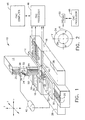
- Figure 1 is a perspective view of a CNC machine tool.
- Figure 2 is a top view of the work table of the machine tool of Figure 1 showing a work piece measurement.
- Figure 1 shows a multi-axis, computer numerically controlled (CNC) machine tool 10.
- the machine tool 10 operates on a coordinate axis system having an X-axis and an Y-axis oriented horizontally and a Z-axis oriented vertically.
- CNC computer numerically controlled
- the CNC machine tool 10 includes a vertical column 12 mounted on a linearly movable platform 14.
- the platform 14 is slideably supported on horizontal X-direction guide rails 16 that are rigidly connected to a machine base 18, parallel to the X-axis.
- the machine base 18 also has horizontal Y-direction guide rails 20 rigidly connected thereto and extending perpendicular to the X-direction guide rails 16.
- a work table carrier 22 is slideably supported on the Y-direction guide rails 20.
- a rotary work table 24 is rotatively mounted on the work table carrier 22 for rotation about an axis of rotation, which is parallel to the Z-axis.
- the rotary work table 24 supports for a work piece 26 to be machined.
- a spindle carrier 28 is slideably supported on vertical Z-direction guide rails 30 that are rigidly connected to the column 12, parallel to the Z-axis. Thus, the spindle carrier 28 can be moved vertically, along the Z-axis, towards or away from the work piece 26 clamped to the rotary work table 24.
- the spindle carrier 28 supports a spindle mechanism 32 that includes a tool holder 34 capable of receiving various cutting tools, measuring devices and probes used in the machining process.
- the tool holder 34 can thus be moved along the X-, Y- and Z-axes so as to be accurately positioned with respect to the work piece 26.
- the machine tool 10 includes a conventional measuring system for tracking the relative position of the tool holder 34.
- the measuring system can comprise a linear scale 35 for each coordinate axis as shown in Figure 1.
- a plurality of rotary encoders could be used instead of linear scales.
- the machine tool 10 includes a conventional system for cooling the work piece 26 and removing debris during machining operations.
- a nozzle 36 is incorporated into the spindle mechanism 32 and arranged to spray a stream of coolant onto the work piece 26 at a flow rate of many gallons per minute.
- the coolant is collected in a sump 38, and a pump 40 is provided for circulating the coolant, as is shown schematically in Figure 1.
- the machine tool 10 also includes a means for measuring the work piece temperature.
- this means comprises a temperature sensor 42 situated to sense the temperature of the coolant as it flows into the sump 38. Because of the coolant's high thermal transmitting capability, the coolant and the work piece 26 will assume substantially the same temperature after only a short period of work piece flooding. Thus, by placing the temperature sensor 42 in the coolant flow just downstream of the work piece 26, it will effectively provide an indication of the work piece temperature. It should be understood that other approaches to measuring the work piece temperature are also applicable.
- Additional temperature sensors 44 are provided for monitoring the temperature of the machine tool 10, particularly the measuring system that tracks the positioning of the tool holder 34.
- each one of the three linear scales 35 has at least one of the machine temperature sensors 44 attached thereto.
- Control of the CNC machine 10 is provided by a CNC processor 46 generally, but not necessarily, mounted near or in the vicinity of the column 12.
- the CNC processor 46 is capable of being programmed to machine a work piece as well as making necessary work piece measurements.
- the CNC processor 46 also has computer calculating capability. Programs are loaded in a conventional manner using CNC programs via a host digital numerical control (DNC) computer 48. These programs, typically referred to as NC programs, provide data for controlling the operation of the machine tool 10.
- the CNC processor 46 also receives input from each of the temperature sensors 42 and 44.
- an appropriate tool (not shown in Figure 1) is inserted into the tool holder 34, and the work piece 26 is clamped onto the rotary work table 24.
- the CNC processor 46 controls the movement of the platform 14, the work table carrier 22, the rotary work table 24 and the spindle carrier 28 to position the tool relative to the work piece 26 so that the machining operation can be performed. At some point in the operation, it may become necessary to measure a dimension of the work piece 26. To do this, the tool is removed and a sensing probe 50 is inserted in the tool holder 34.
- One type of probe that is suitable for use as the probe 50 is a conventional touch trigger type of displacement probe, although other types of probes could be used as well.
- Figure 2 schematically shows how an X-direction dimension of the work piece 26 is measured.
- the probe 50 is moved along the X-axis until it contacts the work piece 26 at a point A on a first side thereof.
- the contact of the probe 50 against the work piece 26 triggers the probe 50 to send a signal to the CNC processor 46, and the X-axis position of point A is stored in the CNC processor 46.
- the probe 50 is then moved into contact with the opposite side of the work piece 26 at a point B on the X-axis.
- the X-axis position of point B is also stored in the CNC processor 46.
- the CNC processor 46 uses the two stored position values to determine the observed dimension (i.e., the distance between points A and B) of the work piece 26.
- the observed dimension is the diameter of the cylindrical work piece 26, although the same measuring process would apply to other dimensions and differently shaped work pieces.
- the same process could be applied to measuring dimensions in the Y- or Z-directions.
- measurement error will occur if the machine tool 10 and the work piece 26 are at different temperatures because the respective thermal expansion will be different. Measurement error will also occur if the machine tool 10 and the work piece 26 have different coefficients of expansion and the work piece 26, the machine tool 10 or both are not at the standard reference temperature (typically 68 °F (20 °C)).
- the present invention provides for automatic compensation of such measurement errors by accounting for the difference between the machine tool's thermal expansion and the work piece's thermal expansion.
- the first step of the compensation process is to determine the amount of work piece thermal expansion from the size that the work piece 26 would be at the standard reference temperature.
- the work piece's coefficient of thermal expansion is included in the NC program and is thus stored in the CNC processor 46.
- the next step is to determine the amount of thermal expansion of the machine tool 10 along the X-axis from the standard reference temperature.
- the machine tool's coefficient of thermal expansion is also included in the NC program and stored in the CNC processor 46. This can be an effective coefficient of expansion for the machine tool 10 that is typically stated by the original equipment manufacturer or else established empirically by the end user. In some machine tools, different rates of expansion are experienced along the three coordinate axes.
- E m in the above equation would be the coefficient of thermal expansion for the X-axis because the dimension being measured extends in the X-direction. If a dimension extending in another direction were being measured, then the coefficient of thermal expansion for that axis would be used.
- the difference of the two thermal expansions (E w - E m ) represents the thermally induced error or distortion.
- the actual dimension of the work piece 26 can be determined from the observed dimension as measured by the probe 50 and the calculated thermal expansions.
- the machine tool 10 can automatically compensate for measuring error encountered from on machine probing when measuring work pieces having different coefficients of thermal expansion and/or at non-standard temperature.
- the CNC processor 46 is capable of automatic compensation for thermally induced measurement error.
- the automatic measurement error compensation of the present invention optimizes measuring accuracy by establishing the work piece's standard temperature size.
- the observed dimension in the X-direction would by x 2 -x 1
- the observed dimension in the Y-direction would be y 2 -y 1
- the observed dimension in the Z-direction would be z 2 -z 1 .
- the above equations would be used for the observed dimension for each direction to determine the actual dimension in each direction. These values would then be combined to determine the overall actual dimension.
Landscapes
- Physics & Mathematics (AREA)
- General Physics & Mathematics (AREA)
- Engineering & Computer Science (AREA)
- Mechanical Engineering (AREA)
- Automatic Control Of Machine Tools (AREA)
- Length Measuring Devices With Unspecified Measuring Means (AREA)
- Machine Tool Sensing Apparatuses (AREA)
Applications Claiming Priority (2)
| Application Number | Priority Date | Filing Date | Title |
|---|---|---|---|
| US50161500A | 2000-02-10 | 2000-02-10 | |
| US501615 | 2000-02-10 |
Publications (1)
| Publication Number | Publication Date |
|---|---|
| EP1128156A1 true EP1128156A1 (en) | 2001-08-29 |
Family
ID=23994300
Family Applications (1)
| Application Number | Title | Priority Date | Filing Date |
|---|---|---|---|
| EP01301059A Withdrawn EP1128156A1 (en) | 2000-02-10 | 2001-02-07 | Method and apparatus for automatically compensating for measurement error |
Country Status (4)
| Country | Link |
|---|---|
| EP (1) | EP1128156A1 (tr) |
| JP (1) | JP2001269841A (tr) |
| BR (1) | BR0100462A (tr) |
| TR (1) | TR200100390A2 (tr) |
Cited By (19)
| Publication number | Priority date | Publication date | Assignee | Title |
|---|---|---|---|---|
| WO2003014655A1 (de) * | 2001-08-09 | 2003-02-20 | Carl Zeiss | Korrektur des temperaturfehlers bei einer messung mit einem koordinatenmessgerät |
| WO2004076120A1 (en) * | 2003-02-28 | 2004-09-10 | Maus S.P.A. | A method for processing products having low tolerances by removing shavings |
| WO2005071350A1 (de) * | 2004-01-26 | 2005-08-04 | Carl Zeiss Industrielle Messtechnik Gmbh | Messsystem zum geometrischen vermessen eines werkstückes |
| EP1748278A1 (de) * | 2005-07-29 | 2007-01-31 | Hexagon Metrology GmbH | Verfahren zur Korrektur des thermischen Verhaltens eines Messprozesses oder der thermischen Ausdehnung eines Werkstückes sowie Koordinatenmessgerät zur Durchführung des Verfahrens |
| US7266903B2 (en) * | 2005-03-31 | 2007-09-11 | Okuma Corporation | Method for correcting thermal displacement in a machine tool |
| WO2010044067A1 (de) * | 2008-10-14 | 2010-04-22 | Bystronic Laser Ag | Thermische strahlbearbeitungsmaschine mit längenausgleich und verfahren hierfür |
| CN102554705A (zh) * | 2012-02-28 | 2012-07-11 | 天津微纳制造技术有限公司 | 一种光学自由曲面补偿加工方法 |
| ITBS20110020A1 (it) * | 2011-02-25 | 2012-08-26 | Camozzi Machine Tools S P A | Macchina utensile con compensazione delle deformazioni termiche di organi di misura |
| EP2284485A3 (de) * | 2004-12-16 | 2013-05-15 | Werth Messtechnik GmbH | Koordinatenmessgerät sowie Verfahren zum Messen mit einem Koordinatenmessgerät |
| US8711365B2 (en) | 2004-12-16 | 2014-04-29 | Werth Messtechnik Gmbh | Coordinate measuring device and method for measuring with a coordinate measuring device |
| WO2014076454A1 (en) * | 2012-11-14 | 2014-05-22 | Renishaw Plc | Method and apparatus for measuring a workpiece with a machine tool |
| CN105269406A (zh) * | 2014-07-23 | 2016-01-27 | 沈阳机床(集团)设计研究院有限公司上海分公司 | 双转台五轴联动机床旋转轴的误差补偿方法 |
| CN106052613A (zh) * | 2016-07-29 | 2016-10-26 | 商丘金振源电子科技有限公司 | 一种测量产品尺寸的检测治具 |
| CN106346304A (zh) * | 2015-07-17 | 2017-01-25 | 发那科株式会社 | 机床的热位移修正装置 |
| US9739606B2 (en) | 2011-08-09 | 2017-08-22 | Renishaw Plc | Method and apparatus for inspecting workpieces |
| US9989347B2 (en) | 2013-05-10 | 2018-06-05 | Renishaw Plc | Method and apparatus for inspecting workpieces |
| CN110625441A (zh) * | 2019-11-05 | 2019-12-31 | 东莞信柏结构陶瓷股份有限公司 | 在数控机床上在机检测产品尺寸的方法 |
| CN110977612A (zh) * | 2019-11-18 | 2020-04-10 | 上海爱堃智能系统有限公司 | Cnc数控加工在线测量误差修正方法及系统 |
| CN111872743A (zh) * | 2020-07-21 | 2020-11-03 | 天津大学 | 卧式加工中心热致直线度-垂直度误差检测装置及其方法 |
Families Citing this family (3)
| Publication number | Priority date | Publication date | Assignee | Title |
|---|---|---|---|---|
| JP4803491B2 (ja) * | 2006-11-02 | 2011-10-26 | 株式会社ニイガタマシンテクノ | 工作機械における位置補正装置 |
| JP5381922B2 (ja) * | 2010-07-22 | 2014-01-08 | トヨタ自動車株式会社 | 加工装置による被加工物の加工方法 |
| JP6757391B2 (ja) * | 2018-11-19 | 2020-09-16 | Dmg森精機株式会社 | 測定方法 |
Citations (5)
| Publication number | Priority date | Publication date | Assignee | Title |
|---|---|---|---|---|
| US3332153A (en) * | 1964-08-31 | 1967-07-25 | Bausch & Lomb | Temperature compensating system |
| US4392195A (en) * | 1979-10-03 | 1983-07-05 | Inoue-Japax Research Incorporated | Method of and apparatus for controlledly moving a movable element |
| DE3620118A1 (de) * | 1986-06-14 | 1987-12-17 | Zeiss Carl Fa | Verfahren zur bestimmung bzw. korrektur des temperaturfehlers bei laengenmessungen |
| EP0546784A2 (en) * | 1991-12-11 | 1993-06-16 | Renishaw Metrology Limited | Temperature sensor for coordinate positioning apparatus |
| JPH068107A (ja) * | 1992-06-29 | 1994-01-18 | Hitachi Seiko Ltd | 工作機械における熱変位補正方法 |
-
2001
- 2001-02-07 EP EP01301059A patent/EP1128156A1/en not_active Withdrawn
- 2001-02-08 BR BR0100462A patent/BR0100462A/pt not_active Application Discontinuation
- 2001-02-08 TR TR2001/00390A patent/TR200100390A2/tr unknown
- 2001-02-09 JP JP2001033021A patent/JP2001269841A/ja not_active Withdrawn
Patent Citations (5)
| Publication number | Priority date | Publication date | Assignee | Title |
|---|---|---|---|---|
| US3332153A (en) * | 1964-08-31 | 1967-07-25 | Bausch & Lomb | Temperature compensating system |
| US4392195A (en) * | 1979-10-03 | 1983-07-05 | Inoue-Japax Research Incorporated | Method of and apparatus for controlledly moving a movable element |
| DE3620118A1 (de) * | 1986-06-14 | 1987-12-17 | Zeiss Carl Fa | Verfahren zur bestimmung bzw. korrektur des temperaturfehlers bei laengenmessungen |
| EP0546784A2 (en) * | 1991-12-11 | 1993-06-16 | Renishaw Metrology Limited | Temperature sensor for coordinate positioning apparatus |
| JPH068107A (ja) * | 1992-06-29 | 1994-01-18 | Hitachi Seiko Ltd | 工作機械における熱変位補正方法 |
Non-Patent Citations (1)
| Title |
|---|
| PATENT ABSTRACTS OF JAPAN vol. 018, no. 203 (M - 1590) 11 April 1994 (1994-04-11) * |
Cited By (27)
| Publication number | Priority date | Publication date | Assignee | Title |
|---|---|---|---|---|
| US7188432B2 (en) | 2001-08-09 | 2007-03-13 | Carl Zeiss Industrielle Messtechnik Gmbh | Correction of the temperature error during a measurement conducted by a coordinate measuring device |
| WO2003014655A1 (de) * | 2001-08-09 | 2003-02-20 | Carl Zeiss | Korrektur des temperaturfehlers bei einer messung mit einem koordinatenmessgerät |
| WO2004076120A1 (en) * | 2003-02-28 | 2004-09-10 | Maus S.P.A. | A method for processing products having low tolerances by removing shavings |
| WO2005071350A1 (de) * | 2004-01-26 | 2005-08-04 | Carl Zeiss Industrielle Messtechnik Gmbh | Messsystem zum geometrischen vermessen eines werkstückes |
| EP2284485A3 (de) * | 2004-12-16 | 2013-05-15 | Werth Messtechnik GmbH | Koordinatenmessgerät sowie Verfahren zum Messen mit einem Koordinatenmessgerät |
| US8711365B2 (en) | 2004-12-16 | 2014-04-29 | Werth Messtechnik Gmbh | Coordinate measuring device and method for measuring with a coordinate measuring device |
| US7266903B2 (en) * | 2005-03-31 | 2007-09-11 | Okuma Corporation | Method for correcting thermal displacement in a machine tool |
| EP1748278A1 (de) * | 2005-07-29 | 2007-01-31 | Hexagon Metrology GmbH | Verfahren zur Korrektur des thermischen Verhaltens eines Messprozesses oder der thermischen Ausdehnung eines Werkstückes sowie Koordinatenmessgerät zur Durchführung des Verfahrens |
| WO2010044067A1 (de) * | 2008-10-14 | 2010-04-22 | Bystronic Laser Ag | Thermische strahlbearbeitungsmaschine mit längenausgleich und verfahren hierfür |
| CN103442845A (zh) * | 2011-02-25 | 2013-12-11 | 银丝-贝拉尔迪有限公司 | 具有热变形补偿的测量工具的机床 |
| ITBS20110020A1 (it) * | 2011-02-25 | 2012-08-26 | Camozzi Machine Tools S P A | Macchina utensile con compensazione delle deformazioni termiche di organi di misura |
| WO2012114168A1 (en) * | 2011-02-25 | 2012-08-30 | Innse-Berardi S.P.A. | Machine tool with thermal deformation compensation of measuring means |
| US9753448B2 (en) | 2011-02-25 | 2017-09-05 | Innse-Berardi S.P.A. | Machine tools which compensate for thermal deformation |
| US9739606B2 (en) | 2011-08-09 | 2017-08-22 | Renishaw Plc | Method and apparatus for inspecting workpieces |
| CN102554705B (zh) * | 2012-02-28 | 2013-12-11 | 天津微纳制造技术有限公司 | 一种光学自由曲面补偿加工方法 |
| CN102554705A (zh) * | 2012-02-28 | 2012-07-11 | 天津微纳制造技术有限公司 | 一种光学自由曲面补偿加工方法 |
| WO2014076454A1 (en) * | 2012-11-14 | 2014-05-22 | Renishaw Plc | Method and apparatus for measuring a workpiece with a machine tool |
| US10048065B2 (en) | 2012-11-14 | 2018-08-14 | Renishaw Plc | Method and apparatus for measuring a part |
| US9989347B2 (en) | 2013-05-10 | 2018-06-05 | Renishaw Plc | Method and apparatus for inspecting workpieces |
| CN105269406A (zh) * | 2014-07-23 | 2016-01-27 | 沈阳机床(集团)设计研究院有限公司上海分公司 | 双转台五轴联动机床旋转轴的误差补偿方法 |
| CN106346304A (zh) * | 2015-07-17 | 2017-01-25 | 发那科株式会社 | 机床的热位移修正装置 |
| US10514676B2 (en) * | 2015-07-17 | 2019-12-24 | Fanuc Corporation | Thermal displacement correction apparatus for machine tool |
| CN106052613A (zh) * | 2016-07-29 | 2016-10-26 | 商丘金振源电子科技有限公司 | 一种测量产品尺寸的检测治具 |
| CN110625441A (zh) * | 2019-11-05 | 2019-12-31 | 东莞信柏结构陶瓷股份有限公司 | 在数控机床上在机检测产品尺寸的方法 |
| CN110977612A (zh) * | 2019-11-18 | 2020-04-10 | 上海爱堃智能系统有限公司 | Cnc数控加工在线测量误差修正方法及系统 |
| CN110977612B (zh) * | 2019-11-18 | 2021-08-03 | 上海爱堃智能系统有限公司 | Cnc数控加工在线测量误差修正方法及系统 |
| CN111872743A (zh) * | 2020-07-21 | 2020-11-03 | 天津大学 | 卧式加工中心热致直线度-垂直度误差检测装置及其方法 |
Also Published As
| Publication number | Publication date |
|---|---|
| TR200100390A3 (tr) | 2001-09-21 |
| BR0100462A (pt) | 2002-02-19 |
| JP2001269841A (ja) | 2001-10-02 |
| TR200100390A2 (tr) | 2001-09-21 |
Similar Documents
| Publication | Publication Date | Title |
|---|---|---|
| EP1128156A1 (en) | Method and apparatus for automatically compensating for measurement error | |
| EP0545658B1 (en) | Automated maintenance system for computer numerically controlled machines | |
| EP3134707B1 (en) | Calibration of measurement probes | |
| US6973738B2 (en) | Measuring method and device, machine tool having such device, and work processing method | |
| US5111590A (en) | Measuring method of machine tool accuracy using a computer aided kinematic transducer link and its apparatus | |
| US4808048A (en) | Method and apparatus for error compensation | |
| WO2000014474A1 (en) | Coordinate measuring machine having a machine tool frame | |
| EP0318557A1 (en) | PROCESS FOR INSPECTING WORKPIECES. | |
| JP4803491B2 (ja) | 工作機械における位置補正装置 | |
| JPS6161744A (ja) | 工作物を計測する方法と装置 | |
| EP1107080B1 (en) | Probe chord error compensation | |
| JP7300374B2 (ja) | 工作機械の誤差計測方法及び工作機械 | |
| CN116748573A (zh) | 一种叶盘铣五轴卧式加工中心一体式床身制造和检测方法 | |
| JP5437693B2 (ja) | 主軸又はアタッチメント主軸の補正値自動計測方法 | |
| JP2022161355A (ja) | 工作機械における運動誤差の導出方法および導出装置 | |
| JPH08141883A (ja) | 工作機械の熱変位補正方法 | |
| JPH09131642A (ja) | 数値制御工作機械精度検査装置並びに該数値制御工作 機械の熱変位検査方法及び精度検査方法 | |
| KR101823052B1 (ko) | 자동 선반 가공 후 자동 보정을 위한 가공물 측정 방법 | |
| JPH05185304A (ja) | 自動旋盤 | |
| JP2021076425A (ja) | 工作機械における対象物の位置計測方法及び位置計測システム、位置計測プログラム | |
| Liu et al. | The application of the double-readheads planar encoder system for error calibration of computer numerical control machine tools | |
| JP2760986B2 (ja) | 工具長測定方法 | |
| Kim et al. | Synthesis of the 3D artefact for quick identification of thermal errors in machine tools | |
| KR0161339B1 (ko) | 컴퓨터수치제어 공작기계의 열변형 오차측정장치 | |
| JPH07204991A (ja) | 変位検出形測定ヘッドを用いた測定システム |
Legal Events
| Date | Code | Title | Description |
|---|---|---|---|
| PUAI | Public reference made under article 153(3) epc to a published international application that has entered the european phase |
Free format text: ORIGINAL CODE: 0009012 |
|
| AK | Designated contracting states |
Kind code of ref document: A1 Designated state(s): AT BE CH CY DE DK ES FI FR GB GR IE IT LI LU MC NL PT SE TR |
|
| AX | Request for extension of the european patent |
Free format text: AL;LT;LV;MK;RO;SI |
|
| 17P | Request for examination filed |
Effective date: 20020228 |
|
| AKX | Designation fees paid |
Free format text: DE FR GB |
|
| 17Q | First examination report despatched |
Effective date: 20020812 |
|
| GRAP | Despatch of communication of intention to grant a patent |
Free format text: ORIGINAL CODE: EPIDOSNIGR1 |
|
| STAA | Information on the status of an ep patent application or granted ep patent |
Free format text: STATUS: THE APPLICATION IS DEEMED TO BE WITHDRAWN |
|
| 18D | Application deemed to be withdrawn |
Effective date: 20040629 |