EP1126284A2 - Gekühlter NMR-Probenkopf mit gleichmässiger Temperierung der Messprobe - Google Patents
Gekühlter NMR-Probenkopf mit gleichmässiger Temperierung der Messprobe Download PDFInfo
- Publication number
- EP1126284A2 EP1126284A2 EP00127797A EP00127797A EP1126284A2 EP 1126284 A2 EP1126284 A2 EP 1126284A2 EP 00127797 A EP00127797 A EP 00127797A EP 00127797 A EP00127797 A EP 00127797A EP 1126284 A2 EP1126284 A2 EP 1126284A2
- Authority
- EP
- European Patent Office
- Prior art keywords
- room temperature
- tube
- probe head
- sample tube
- heating
- Prior art date
- Legal status (The legal status is an assumption and is not a legal conclusion. Google has not performed a legal analysis and makes no representation as to the accuracy of the status listed.)
- Granted
Links
- 238000012360 testing method Methods 0.000 title description 7
- 238000005481 NMR spectroscopy Methods 0.000 claims abstract description 55
- 238000010521 absorption reaction Methods 0.000 claims abstract description 10
- 239000000126 substance Substances 0.000 claims abstract description 10
- 239000000523 sample Substances 0.000 claims description 109
- 238000010438 heat treatment Methods 0.000 claims description 66
- 230000005855 radiation Effects 0.000 claims description 51
- 239000000463 material Substances 0.000 claims description 28
- 239000004020 conductor Substances 0.000 claims description 15
- 125000006850 spacer group Chemical group 0.000 claims description 9
- 230000008878 coupling Effects 0.000 claims description 5
- 238000010168 coupling process Methods 0.000 claims description 5
- 238000005859 coupling reaction Methods 0.000 claims description 5
- 238000000034 method Methods 0.000 abstract description 4
- 230000008569 process Effects 0.000 abstract description 3
- 230000001771 impaired effect Effects 0.000 abstract 1
- 238000011161 development Methods 0.000 description 15
- 230000018109 developmental process Effects 0.000 description 15
- 239000000835 fiber Substances 0.000 description 14
- 239000011521 glass Substances 0.000 description 8
- 238000005259 measurement Methods 0.000 description 8
- 238000005496 tempering Methods 0.000 description 5
- 230000008901 benefit Effects 0.000 description 4
- 239000003365 glass fiber Substances 0.000 description 4
- 238000000655 nuclear magnetic resonance spectrum Methods 0.000 description 4
- 239000010453 quartz Substances 0.000 description 4
- VYPSYNLAJGMNEJ-UHFFFAOYSA-N silicon dioxide Inorganic materials O=[Si]=O VYPSYNLAJGMNEJ-UHFFFAOYSA-N 0.000 description 4
- 230000015572 biosynthetic process Effects 0.000 description 3
- 230000000903 blocking effect Effects 0.000 description 3
- 230000000694 effects Effects 0.000 description 3
- 238000009413 insulation Methods 0.000 description 3
- 230000004323 axial length Effects 0.000 description 2
- 239000010949 copper Substances 0.000 description 2
- 238000010586 diagram Methods 0.000 description 2
- 239000004744 fabric Substances 0.000 description 2
- 238000004128 high performance liquid chromatography Methods 0.000 description 2
- 230000001678 irradiating effect Effects 0.000 description 2
- 239000007788 liquid Substances 0.000 description 2
- 238000004811 liquid chromatography Methods 0.000 description 2
- 238000012545 processing Methods 0.000 description 2
- 230000001105 regulatory effect Effects 0.000 description 2
- 230000000630 rising effect Effects 0.000 description 2
- 229910052594 sapphire Inorganic materials 0.000 description 2
- 239000010980 sapphire Substances 0.000 description 2
- 230000003068 static effect Effects 0.000 description 2
- 238000011144 upstream manufacturing Methods 0.000 description 2
- 229910018072 Al 2 O 3 Inorganic materials 0.000 description 1
- 238000012935 Averaging Methods 0.000 description 1
- RYGMFSIKBFXOCR-UHFFFAOYSA-N Copper Chemical compound [Cu] RYGMFSIKBFXOCR-UHFFFAOYSA-N 0.000 description 1
- 238000012565 NMR experiment Methods 0.000 description 1
- 230000002730 additional effect Effects 0.000 description 1
- 239000000853 adhesive Substances 0.000 description 1
- 238000004026 adhesive bonding Methods 0.000 description 1
- 230000001070 adhesive effect Effects 0.000 description 1
- 229910052782 aluminium Inorganic materials 0.000 description 1
- XAGFODPZIPBFFR-UHFFFAOYSA-N aluminium Chemical compound [Al] XAGFODPZIPBFFR-UHFFFAOYSA-N 0.000 description 1
- 238000004458 analytical method Methods 0.000 description 1
- 230000002238 attenuated effect Effects 0.000 description 1
- 239000011324 bead Substances 0.000 description 1
- 230000005540 biological transmission Effects 0.000 description 1
- 230000001427 coherent effect Effects 0.000 description 1
- 238000001816 cooling Methods 0.000 description 1
- 229910052802 copper Inorganic materials 0.000 description 1
- 238000013016 damping Methods 0.000 description 1
- 230000006866 deterioration Effects 0.000 description 1
- 238000009826 distribution Methods 0.000 description 1
- 238000005516 engineering process Methods 0.000 description 1
- 239000011888 foil Substances 0.000 description 1
- 230000017525 heat dissipation Effects 0.000 description 1
- 230000006872 improvement Effects 0.000 description 1
- 238000003780 insertion Methods 0.000 description 1
- 230000037431 insertion Effects 0.000 description 1
- 238000012594 liquid chromatography nuclear magnetic resonance Methods 0.000 description 1
- 238000004519 manufacturing process Methods 0.000 description 1
- 229910052751 metal Inorganic materials 0.000 description 1
- 239000002184 metal Substances 0.000 description 1
- 238000012986 modification Methods 0.000 description 1
- 230000004048 modification Effects 0.000 description 1
- 230000003287 optical effect Effects 0.000 description 1
- 230000000704 physical effect Effects 0.000 description 1
- 230000009467 reduction Effects 0.000 description 1
- 239000012858 resilient material Substances 0.000 description 1
- 238000000926 separation method Methods 0.000 description 1
- 239000007787 solid Substances 0.000 description 1
- XLYOFNOQVPJJNP-UHFFFAOYSA-N water Substances O XLYOFNOQVPJJNP-UHFFFAOYSA-N 0.000 description 1
Images


Classifications
-
- G—PHYSICS
- G01—MEASURING; TESTING
- G01R—MEASURING ELECTRIC VARIABLES; MEASURING MAGNETIC VARIABLES
- G01R33/00—Arrangements or instruments for measuring magnetic variables
- G01R33/20—Arrangements or instruments for measuring magnetic variables involving magnetic resonance
- G01R33/28—Details of apparatus provided for in groups G01R33/44 - G01R33/64
- G01R33/30—Sample handling arrangements, e.g. sample cells, spinning mechanisms
-
- G—PHYSICS
- G01—MEASURING; TESTING
- G01R—MEASURING ELECTRIC VARIABLES; MEASURING MAGNETIC VARIABLES
- G01R33/00—Arrangements or instruments for measuring magnetic variables
- G01R33/20—Arrangements or instruments for measuring magnetic variables involving magnetic resonance
- G01R33/28—Details of apparatus provided for in groups G01R33/44 - G01R33/64
- G01R33/32—Excitation or detection systems, e.g. using radio frequency signals
- G01R33/34—Constructional details, e.g. resonators, specially adapted to MR
- G01R33/34015—Temperature-controlled RF coils
- G01R33/34023—Superconducting RF coils
-
- G—PHYSICS
- G01—MEASURING; TESTING
- G01R—MEASURING ELECTRIC VARIABLES; MEASURING MAGNETIC VARIABLES
- G01R33/00—Arrangements or instruments for measuring magnetic variables
- G01R33/20—Arrangements or instruments for measuring magnetic variables involving magnetic resonance
- G01R33/28—Details of apparatus provided for in groups G01R33/44 - G01R33/64
- G01R33/32—Excitation or detection systems, e.g. using radio frequency signals
- G01R33/34—Constructional details, e.g. resonators, specially adapted to MR
- G01R33/34092—RF coils specially adapted for NMR spectrometers
Definitions
- NMR nuclear magnetic resonance
- HF high frequency
- Such a cooled NMR probe head is known, for example, from US-A 5,247,256.
- the probe head is installed in a magnet to generate a highly homogeneous, static B 0 field and contains RF reception coils arranged around a z-axis, which use suitable heat exchangers and heat conduction elements during operation up to temperatures of approx. 10 - 25 K. cooled in order to improve the signal-to-noise ratio of the received NMR signal during the measurement.
- the RF receiving coils are located in an evacuated space, which is essentially formed by a generally metallic housing of the sample head, which is broken through by a room temperature tube arranged cylindrically around the z-axis for receiving a sample tube.
- the otherwise normally metallic room temperature tube in the axial area of the coils is replaced by an RF-permeable inner tube, usually a glass tube, which connects vacuum-tight to the metallic parts of the room temperature tube.
- the sample tube is inserted after insertion into the room temperature pipe from below using a warm air flow through the room temperature pipe essentially at a desired temperature (usually about 300 K).
- a desired temperature usually about 300 K.
- the problem arises that the Measurement sample the considerably cooler environment of the cooled to 10 - 25 K. NMR resonators "see” and radiate their heat there in the radial direction. This outgoing heat must continuously from the rising warm tempering air flow be fed back so that the measurement sample essentially remains at the desired temperature. This process now has the consequence that an axial and radial temperature gradient arises in the test sample, which is the NMR measurement is very disturbing.
- the object of the present invention is therefore a cooled NMR probe head with the features mentioned in the introduction, in which the Temperature gradient in the z direction during operation is significantly reduced without the NMR measurement is affected.
- this task is as surprisingly simple as effective way solved in that between the RF receiving coil system and the sample tube in a radial direction In the direction surrounding, extended in the z-direction temperature control device which is almost completely transparent to RF fields, at least but has an absorption ⁇ 5%, preferably ⁇ 1% for RF fields.
- the NMR probe heads according to the invention include those with exchangeable sample tubes also so-called flow heads, in which the sample tube remains permanently installed and the liquid to be examined through a thin pipe on one side (below) and on the other side (above).
- Such probes can both in continuous flow as well as in flow and stop mode (for one extended measurement period) can be used.
- These probes are one hand used for a quick sample introduction, on the other hand also as one Very meaningful analysis stage, that of a liquid chromatography separation cell is connected downstream. In the former case one speaks of flow probes, in the second by LC-NMR coupling.
- Such probes are also referred to as LC heads (Liquid Chromatography, in particular also HPLC (High Pressure Liquid Chromatography).
- Such probe heads can in particular Dimensions from cryo technology and therefore from those according to the invention Modifications benefit.
- the advantage of such a temperature control device compared to the known use of a heated air flow for The test tube lies mainly in the fact that the heating output is evenly above the entire axial length of the sample tube can be made. The middle one The area is tempered as well as the edge areas. In this way axial temperature gradients can be effectively prevented.
- Such a heating device according to the invention can be used both alone and can also be used together with air flow temperature control.
- a Combining both types of heating is particularly advantageous since it is the residual Optimally suppressed temperature gradients.
- a conventional heated airflow occurs without the inventive one Heater usually at the bottom of the sample tube into the room temperature pipe, from then on it gives off its heat to the Sample tube and cools in the axial direction when rising ever further.
- the temperature of the heated air flow in the upper area of the sample tube will therefore always be smaller than that in the lower area, which inevitably changes the temperature control in the upper area of the Sample tube reduced.
- an axial temperature gradient always arises, which increases by increasing the amount of air per unit of time can be reduced somewhat, but in principle cannot be prevented.
- there are narrow limits to the corresponding countermeasures because if the air volume is too large per unit of time, a vibration-free position or clean rotation of the sample tube can no longer be guaranteed.
- the temperature control device in the NMR probe head according to the invention can be opened technically completely different ways. For example heating with electric current, but also heating by radiation or by heat conduction in the area around the sample tube.
- a particularly preferred embodiment of the NMR probe head according to the invention is characterized in that the temperature control device a the sample tube radially in the axial area of the RF receiving coil system surrounding layer with a radial thickness ⁇ 1 mm, preferably ⁇ 50 microns, which is made up of material which emits radiation in a wavelength range 100nm ⁇ ⁇ ⁇ 100 ⁇ m at least partially absorbed, and which for Radiation in a wavelength range ⁇ > 100mm is transparent.
- a radial thickness ⁇ 1 mm preferably ⁇ 50 microns, which is made up of material which emits radiation in a wavelength range 100nm ⁇ ⁇ ⁇ 100 ⁇ m at least partially absorbed, and which for Radiation in a wavelength range ⁇ > 100mm is transparent.
- a heater is preferred for uniform heating of the layer provided in the NMR probe head according to the invention, which is based on technical different ways can be designed.
- the heating device a device for irradiating the layer with radiation from the wavelength range 100nm ⁇ ⁇ ⁇ 100 ⁇ m, especially with thermal radiation. This means that the layer can be heated evenly without contact.
- the device for irradiating the layer is preferably on the HF receiving coil system facing side of the room temperature tube arranged. Since the receiving coil system is usually evacuated Space is housed, the radiant heat can be unhindered by the vacuum get to the heating layer.
- the radiation-absorbing heating layer can cover the room temperature pipe surround.
- the layer can also be around the room temperature pipe around in the axially extending, circumferentially spaced apart Strips may be arranged.
- a development in which the layer is electrically conductive is particularly preferred and can be heated by applying an electrical voltage.
- the temperature control device one or more heating loops made of thin comprises in particular layered, electrically highly conductive material, the each have a forward and a return conductor, the forward and return conductors the heating loops are electrically connected at one end and can be fed with heating current from a power source at the other end.
- the heating loops are made of an electrically conductive layer are the sample tube in the axial area of the RF receiving coil system radially surrounds, has a radial thickness ⁇ 1mm, preferably ⁇ 50 ⁇ m and transparent for radiation in a wavelength range ⁇ > 100mm is.
- this layer can also be the same as that described above Embodiments to be radiation absorbing, so that heating is possible in two different ways.
- the forward and return conductors of the heating loops are particularly preferably bifilar the smallest possible distance from each other to form a to keep disturbing magnetic field as low as possible when current flows.
- the forward and return conductors of the heating loops consist of two superimposed elongated strips consist of a Insulating layer or an insulating strip are electrically isolated from each other.
- the temperature control device can be constructed so that one or several heating loops arranged helically around the room temperature pipe are.
- heating loops can also be used at a distance from each other in the circumferential direction around the z-axis of the room temperature pipe are arranged around and parallel to the z-direction extend.
- the heating loops are advantageously spatially oriented so that their coupling to the RF receiving coil system is minimal.
- the heating loops from a material which is as good an electrical conductor as possible (for example Cu), the conductors having rectangular, preferably square or circular cross sections (typically of the order of magnitude of 10 ⁇ m ⁇ 10 ⁇ m or smaller ).
- the room temperature tube remains very permeable to the HF fields, and the HF losses are kept very low due to both the small surfaces of the heating conductors and the good electrical (and therefore HF) conductivity .
- a low-pass filter can be placed between the power source and the heating loops be provided in order to avoid signal carryover and residual attenuation to keep low.
- a further development is also preferred, in which between the current source and the heating loops a parallel resonant circuit is provided, the resonance frequency at the most sensitive RF frequency relevant for the NMR measurement lies.
- a blocking circuit also prevents the transmission of Interference signals to the RF receiving coil system and minimizes unwanted Coupling of the RF signals through the heating loops.
- the current source is the Heating loop fed with alternating current.
- the angular frequency ⁇ H should be chosen through the heating loops so that the corresponding side bands lie outside the observable NMR spectrum.
- a heating layer and / or heating loops are constructed from material with high thermal conductivity, because then the heating can take place particularly uniformly over the entire surface of the corresponding heating devices, which leads to the formation of Counteracts temperature gradients in the sample tube.
- a particularly preferred embodiment of the NMR probe head according to the invention provides that between the RF receiving coil system and the room temperature pipe surrounding the room temperature pipe in the radial direction, Extended radiation shields are arranged in the z direction, which constructed from one or more materials oriented in the z direction are almost completely transparent to RF fields, or at least one Have absorption ⁇ 5%, preferably ⁇ 1% for RF fields.
- the RF coils and the room temperature radiation shield only materials that have an orientation in the z direction have.
- the axial alignment of the radiation shield material prevents that their finite susceptibility deteriorates the resolution of the NMR signals.
- the materials should have their physical properties forth in the area of high-frequency radiation as transparent as possible his. Most of the time, the latter material property has to be bought with it be that not too high a reflection of the heat loss to the test sample can be expected there.
- the former Wavelength range corresponds to heat radiation at a temperature between approx. 20 K to 300 K, which is the temperature difference between the test sample and equals the cooled NMR coils during the second wavelength range corresponds to radiation with a frequency below 3 GHz, the HF range between a few MHz, which is important for the NMR measurements is below about 1GHz.
- the radiation shields of the NMR probe head according to the invention could theoretically designed as coaxial around the room temperature pipe his.
- the pipe material is usually too thick exhibit.
- the orientation of the film along the z-axis can be, for example, by Mechanical tensile stress can be produced. Is preferred in contrast, an embodiment in which the radiation shields from one unidirectional tissues are constructed. Such unidirectional tissue suitable materials are readily available commercially.
- These fabrics preferably consist of fiber mats, in particular glass fiber mats, made of fibers with diameters of less than 10 ⁇ m and have a total thickness of about 30 ⁇ m.
- fiber mats in particular glass fiber mats, made of fibers with diameters of less than 10 ⁇ m and have a total thickness of about 30 ⁇ m.
- a radial one Sequence of cylindrical single radiation shields can be used of such glass fiber mats also to a helical wrapping of the room temperature pipe on its vacuum side in several layers be thought.
- the radiation shields are from aligned in the z direction, radially around the axis of the room temperature pipe arranged rods or fibers, preferably glass fibers and / or quartz fibers.
- Such fibers have diameters between 10 and 50 ⁇ m commercially available.
- glass filaments with diameters of less than 5 ⁇ m, which are difficult to process should be.
- the radiation shields are made of fiber bundles built up, the overall then a slightly higher mechanical Have stability than the individual filaments and therefore in their processing similar to how bars are easier to handle.
- the rods or fibers can be arranged loosely in space and only be attached to their ends.
- the rods or fibers can also be connected to the room temperature pipe Coaxially arranged carrier tube, preferably on the RF receiving coil system facing side of the room temperature pipe itself attached his.
- the rods or fibers are on the carrier tube or on the room temperature pipe with an adhesive that is transparent to HF radiation attached so that no attenuation of the RF radiation from the test sample the RF receiving coil is due to the gluing.
- rods or fibers are circumferential is also advantageous tightly packed around the axis of the room temperature pipe are arranged so that there is no "optical view" in the radial direction. In this way, the rods or fibers each form one in the circumferential direction coherent radiation shield.
- An embodiment of the invention is also particularly preferred NMR probe head, in which a centering device for centering the sample tube provided in the measuring position around the axis of the room temperature pipe is.
- the transverse temperature gradients radial to the z-axis during operation of a cooled NMR probe head can arise as Product of the heat loss per unit area, the reciprocal of the Mass flow of tempering gas and a symmetry factor, which one Offset or an angular deviation of the axis of the sample tube from the includes z-axis of the room temperature pipe. Because this asymmetry as a factor that goes into the entire product, even with small inclinations the measurement sample within the room temperature pipe considerable influences on the tempering flow. Therefore, with the proposed centering device a not negligible, additional effect in the sense of a Reduction of temperature gradients and an improvement in quality of the NMR signals are effected.
- the centering device comprises one or more between the room temperature pipe and the Sample tubes arranged symmetrically around the z-axis of the room temperature tube distributed spacers.
- spacers can be placed in the area of the bottom of the sample tube its measuring position and / or in the area of the filling opening of the room temperature pipe on the side of the room temperature tube facing the sample tube to be appropriate.
- the spacers can also extend over the entire axial length of the RF receiving coil system.
- the spacers point in the direction the z-axis extended strips are made of resilient material that rigid at its end facing away from the sample glass in its measuring position are connected to the room temperature tube, and which on their the sample tube in its measuring position facing end one for the sample glass have bulged beads, the free leg of the room temperature pipe is present.
- the spacers should be made from one for the HF radiation transparent, preferably magnetically compensated Material built up.
- the spacers consist of sheet metal strips with a thickness of about 100 ⁇ m and a width transverse to the z-axis of about 0.5mm to 2mm, preferably about 1mm.
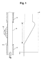
- FIG. 1 shows an NMR probe head according to the invention in a schematic vertical cross section with a temperature control device 11 in the axial area of the inner tube 5 of a room temperature tube 4 and the associated temperature profile shown along the z-axis.
- the temperature control device 11 can for example by an electrical heater and / or by a radiant heater corresponding area on the room temperature pipe 4 in the area of the inner pipe 5 can be realized with the aid of a heating device 19.
- the one shown on the right in the picture Temperature curve along the z-axis shows in the solid line the situation without temperature control and dashed the situation with a regulated temperature control, where an almost constant temperature along the entire z-axis can be observed.
- FIG. 10a Further details of the NMR probe head according to the invention can be found at can be seen from FIG. 10a described below.
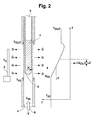
- Fig. 2 is a section of an NMR probe head according to the State of the art shown, in the case of a sample tube 6 radially in the direction to the RF receiving coil system 1 by radiation heat flows Q go off because the receiving coil system 1 at a cryogenic temperature of approximately 25 K is maintained, while the sample tube 6 by means of the Temperature-controlled air flow 8 supplied from below to approximately room temperature to be held. Due to the heat radiation from the sample tube 6 arises taking into account that with the tempering current 8 supplied heat a temperature curve in the axial direction within the Sample tube 6, as shown schematically on the right side of FIG. 2 is.
- transverse gradients can also be used occur when the sample tube 6 is not exactly in the middle of the Room temperature tube 4 is placed, as in Fig. 3a in a horizontal section shown schematically.
- the middle part 5 of the room temperature pipe 4 made of good heat-conducting material. This allows the transversal Temperature gradients (x-y direction) can be greatly reduced. It however, only materials are considered whose absorption for HF radiation is negligible and at the same time the required high thermal conductivity to have. Specifically, sapphire is a suitable material here.
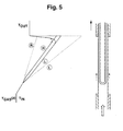
- Fig. 5 the situation is without good heat conduction (dashed) and with good Heat conduction (solid) of the room temperature tube 4, in particular the Inner tube 5 shown.
- the temperature curve along the z-axis can be (apart from averaging the two extremes) practically not influence. Only the temperature curve just before the upper clamping point the sample tube 6 can be lifted.
- a linear temperature gradient can by heat-conducting measures on the room temperature pipe 4 alone cannot be eliminated.
- the temperature control device 11 consists of a heating device 19.
- a layer applied to the sample tube 6 what heat radiation can absorb. So that already results Significantly improved axial temperature profile described above in Fig. 1 in the sample tube 6.
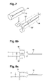
- the temperature control device 11 can also have electrically heatable elements, in particular heating loops 12, 12 ', as opposed in Fig. 6a and in the z-direction along the inner tube 5 of the room temperature tube 4 are shown arranged.
- the inner tube 5 be made of material with good heat conduction (for example sapphire).
- FIG. 6b schematically shows a heating loop 12 "which comprises a relatively large area A. This should be avoided in practice and the area A of the loop should be minimized, since noticeable disturbances of the homogeneous magnetic field B 0 in the area due to an excessively large area Measuring position of the NMR probe head according to the invention is to be feared due to fields running perpendicular to it when current flows through the heating loops.
- Fig. 6c shows an arrangement according to the invention with a helical around the Inner tube 5 wrapped heating loop 12 "', in turn the surface between the two electrical conductors for the reasons mentioned above was kept as low as possible.
- the heating loop 13 consists of two thin layers 13 ', 13 ", which arranged one above the other and electrically through a thin insulation film 14 are separated from each other. This is the generation of disruptive magnetic Fields with current flow through the heating loop 13 practically excluded.
- copper or aluminum are suitable as materials for the layers 13, 13 ′′, for example Al 2 O 3 as the material for the insulating layer 14.
- such an arrangement can also consist of a combination of different materials of the layers 13 ′ and 13 ′′, these should then be selected so that the entire heating loop 13 is magnetically compensated to the outside.
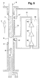
- Temperature control device 11 a low-pass filter 15 before the corresponding Heating loops 12 are switched, as indicated in Fig. 8a.
- FIG. 8b A further improved embodiment is shown schematically in FIG. 8b, where in front of the two inputs of the heating loop 12 each have an electrical blocking circuit 16, 16 'was switched. This blocks the RF frequencies to be measured and additionally minimizes the influence of the heating current on the NMR measurement, and vice versa, carryover and damping of the measuring frequencies.
- an alternating current as heating current through the heating loop 12 the angular frequency of the alternating current can then be selected so that the sidebands generated thereby are outside the observable NMR spectrum.
- the heating power can either be set permanently, corresponding to the radial heat flow to be expected, at a temperature T IN of the temperature gas 8 flowing into the room temperature tube 4 from below and corrected according to the fourth power of this temperature.
- the heating output can also be actively regulated.
- two thermometers 17, 17 'at the lower and upper ends of the inner tube 5 of the room temperature tube 4 can measure the temperatures T 1 and T 2 there and supply them to an electronic control circuit 18 which controls the temperature control device 11.
- the control circuit 18 can consist of a differential amplifier 18 ', which receives the two temperature signals from the thermometers 17, 17' and transmits its differential signal to a controller 18 ", which in turn controls an output stage 18"', which in turn controls the temperature control device 11, in particular a heating loop 12 is supplied with a corresponding heating current.
- NMR probe head has an RF receiving coil system 1, which symmetrical to a z-axis around an axially extending room temperature tube 4 is arranged, which serves to hold a sample tube 6, the one Contains sample substance 7, which are examined with the aid of NMR measurements should.
- the HF reception coil system 1 is mounted on heat conduction elements 2, which are used to cool the HF reception coil system 1 to cryogenic temperatures, generally T 1 ⁇ 25 K.
- the room temperature tube 4 is connected in its upper and lower section to a housing 3 of the NMR probe head, while in its middle section it has an inner tube 5 (usually made of glass) which is permeable to HF fields.
- the sample tube 6 projecting axially into the room temperature tube 4 is kept at the desired temperature during the measurements by means of a gas stream 8, which is approximately at room temperature T 2 ⁇ 300 K.
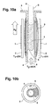
- FIGS. 10a and 10b there are between the receiving coil system 1 and the room temperature tube 4 a plurality of radiation shields 9 arranged, which surround the room temperature tube 4 in the radial direction and are extended along the z-axis.
- the radiation shields 9 are off in the z direction aligned materials, which are almost completely for HF fields are transparent.
- the radiation shields 9 are in the radial direction from one another spaced and do not touch or at least only touch each other or linear, as can be clearly seen in Fig. 10b. They have a radial thickness ⁇ 0.1 mm, preferably ⁇ 50 ⁇ m.
- the preferred material for the Radiation shields 9 use glass or quartz.
- the radiation shields 9 from a unidirectional film unidirectional fabric, especially made of glass fiber mats or axial extending rods or fibers, preferably glass or quartz fibers or Fiber bundles should be built up.
- the radiation shields 9 can be arranged loosely in space and only at their ends attached or, as in the embodiment shown on the room temperature pipe 4 be attached.
- FIGS. 10a, 10b show the invention used temperature control device not shown. You can go to any of the above described types can be realized.
- FIGS. 11a and 11b show a preferred embodiment of the NMR probe head according to the invention with a centering device, the in the embodiment shown, four symmetrically distributed around the z-axis Spacer 10 includes.
Landscapes
- Physics & Mathematics (AREA)
- Condensed Matter Physics & Semiconductors (AREA)
- General Physics & Mathematics (AREA)
- Investigating Or Analyzing Materials Using Thermal Means (AREA)
- Magnetic Resonance Imaging Apparatus (AREA)
Abstract
Description
- Fig. 1
- einen schematischen Vertikalschnitt längs der z-Achse durch einen erfindungsgemäßen NMR-Probenkopf im Bereich des HF-Empfangsspulensystems mit Temperiereinrichtung sowie zugehöriger Temperaturverlauf längs der z-Achse;
- Fig. 2
- einen schematischen Vertikalschnitt durch einen gekühlten NMR-Probenkopf nach dem Stand der Technik mit zugehörigem Temperaturverlauf in Richtung der z-Achse;
- Fig. 3a
- einen schematischen Horizontalschnitt durch eine Anordnung mit asymmetrisch in das Raumtemperaturrohr eingeführtem Probenröhrchen;
- Fig. 3b
- die zur Anordnung nach Fig. 3a zugehörige Temperaturverteilung in z-Richtung;
- Fig. 4a
- einen schematischen Vertikalschnitt durch ein Raumtemperaturrohr mit asymmetrisch eingeführtem Probenröhrchen und angedeuteten Konvektionsströmungen innerhalb der Meßprobe;
- Fig. 4b
- die zugehörigen Temperaturverläufe in Richtung der z-Achse auf der linken und der rechten Seite der Anordnung von Fig. 4a;
- Fig. 5
- ein Schema des Temperaturverlaufs des Temperiergases in Richtung der z-Achse bei asymmetrisch in das Raumtemperaturrohr eingeführtem Probenröhrchen und einer gut wärmeleitenden Innenseite des Raumtemperaturrohres im Bereich der HF-Empfangsspulen;
- Fig. 6a
- eine schematische Darstellung einer Ausführungsform der Erfindung mit zwei gegenüberliegenden elektrischen Heizschlaufen längs des Raumtemperaturrohres;
- Fig. 6b
- wie Fig. 6a, jedoch mit großer von den Heizschlaufen eingeschlossenen Fläche A;
- Fig. 6c
- eine Ausführungsform mit spiralig gewendelter Heizschlaufe;
- Fig. 7
- eine schematische Darstellung einer Ausführungsform mit 2 dünnen, durch eine Isolationsfolie getrennten Schichten einer Heizschlaufe;
- Fig. 8a
- ein Schaltschema für eine Heizschlaufe mit vorgeschalteten Tiefpaß-Filtern;
- Fig. 8b
- wie Fig. 8a, jedoch mit vorgeschalteten Sperrkreisen;
- Fig. 9
- einen schematischen Vertikalschnitt durch eine erfindungsgemäße Anordnung mit Heizeinrichtung, Temperaturfühlern und elektronischer Steuerung der Temperierung;
- Fig.10a
- einen schematischen Vertikalschnitt durch einen erfindungsgemäßen NMR-Probenkopf mit Wärmeschilden zwischen Raumtemperaturrohr und HF-Empfangsspulensystem;
- Fig.10b
- einen schematischen Horizontalschnitt durch eine Anordnung nach Fig. 10a im axialen Bereich des HF-Empfangsspulensystems;
- Fig. 11a
- einen schematischen Vertikalschnitt durch eine erfindungsgemäße Anordnung mit Zentriervorrichtung; und
- Fig. 11b
- einen Horizontalschnitt durch eine Anordnung nach Fig.11a.
Claims (10)
- NMR(= Kernspinresonanz)-Probenkopf mit einem auf kryogene Temperaturen abkühlbaren HF(= Hochfrequenz)-Empfangsspulensystem (1) und einem in einer z-Richtung verlaufenden Raumtemperaturrohr (4) zur Aufnahme eines Probenröhrchens (6), welches mittels NMR-Messung zu untersuchende Probensubstanz (7) enthält,
dadurch gekennzeichnet,
daß zwischen dem HF-Empfangsspulensystem (1) und dem Probenröhrchen (6) eine das Probenröhrchen (6) in radialer Richtung umgebende, in z-Richtung ausgedehnte Temperiereinrichtung (11) angeordnet ist, welche für HF-Felder nahezu vollständig transparent ist, zumindest aber eine Absorption < 5%, vorzugsweise < 1% für HF-Felder aufweist. - NMR-Probenkopf nach Anspruch 1, dadurch gekennzeichnet, daß die Temperiereinrichtung (11) eine das Probenröhrchen (6) im axialen Bereich des HF-Empfangsspulensystems (1) radial umgebende Schicht mit einer radialen Dicke < 1mm, vorzugsweise < 50µm umfaßt, die aus Material aufgebaut ist, welches Strahlung in einem Wellenlängenbereich 100nm < λ ≤ 100µm zumindest teilweise absorbiert, und welches für Strahlung in einem Wellenlängenbereich λ > 100mm transparent ist.
- NMR-Probenkopf nach Anspruch 2, dadurch gekennzeichnet, daß eine Heizeinrichtung (19) zur gleichmäßigen Erwärmung der Schicht vorgesehen ist.
- NMR-Probenkopf nach einem der vorhergehenden Ansprüche, dadurch gekennzeichnet, daß die Temperiereinrichtung (11) eine oder mehrere Heizschlaufen (12, 12', 12"; 13) aus dünnem, elektrisch gut leitfähigem Material umfaßt, die jeweils einen Hin- und einen Rückleiter aufweisen, wobei die Hin- und Rückleiter der Heizschlaufen (12; 13) jeweils einenends elektrisch miteinander verbunden sind und anderenends mit Heizstrom aus einer Stromquelle beschickt werden können.
- NMR-Probenkopf nach einem der Ansprüche 2 bis 4, dadurch gekennzeichnet, daß die das Probenröhrchen (6) radial umgebende Schicht elektrisch beheizbar ist.
- NMR-Probenkopf nach einem der Ansprüche 4 oder 5, dadurch gekennzeichnet, daß die Hin- und Rückleiter der Heizschlaufen (12; 13) aus Materialien von unterschiedlicher magnetischer Suszeptibilität aufgebaut sind, die so ausgewählt sind, daß die gesamte Heizschlaufe (12; 13) jeweils nach außen magnetisch kompensiert ist.
- NMR-Probenkopf nach einem der Ansprüche 3 bis 6, dadurch gekennzeichnet, daß die Heizschlaufen (12; 13) räumlich so orientiert sind, daß ihre Kopplung zum HF-Empfangsspulensystem (1) minimal ist.
- NMR-Probenkopf nach einem der Ansprüche 3 bis 7, dadurch gekennzeichnet, daß zwischen der Stromquelle und den Heizschlaufen (12; 13) ein Tief-Paß-Filter (15) oder ein Parallel-Schwingkreis (16, 16') vorgesehen ist, dessen Resonanzfrequenz bei der empfindlichsten für die NMR-Messung relevanten HF-Frequenz liegt.
- NMR-Probenkopf nach einem der vorhergehenden Ansprüche, dadurch gekennzeichnet, daß zwischen dem HF-Empfangsspulensystem (1) und dem Raumtemperaturrohr (4) mindestens ein, vorzugsweise mehrere das Raum-temperaturrohr (4) in radialer Richtung umgebende, in z-Richtung ausgedehnte Strahlungsschilde (9) angeordnet sind, welche aus einem oder mehreren in z-Richtung ausgerichteten Materialien aufgebaut sind, die für HF-Felder nahezu vollständig transparent sind, zumindest aber eine Absorption < 5%, vorzugsweise < 1% für HF-Felder aufweisen.
- NMR-Probenkopf nach einem der vorhergehenden Ansprüche, dadurch gekennzeichnet, daß eine Zentriervorrichtung zur Zentrierung des Probenröhrchens (6) in Meßposition um die Achse des Raumtemperaturrohres (4) vorgesehen ist, die einen oder mehrere zwischen dem Raumtemperaturrohr (4) und dem Probenröhrchen (6) angeordnete symmetrisch um die z-Achse des Raumtemperaturrohres (4) verteilte Abstandhalter (10) umfaßt, die im Bereich des Bodens des Probenröhrchens (6) in dessen Meßposition und/oder Abstandhalter (10) im Bereich der Einfüllöffnung des Raumtemperaturrohres (4) an der dem Probenröhrchen (6) zugewandten Seite des Raumtemperaturrohres (4) angebracht sind.
Applications Claiming Priority (2)
| Application Number | Priority Date | Filing Date | Title |
|---|---|---|---|
| DE10006323A DE10006323C1 (de) | 2000-02-12 | 2000-02-12 | Gekühlter NMR-Probenkopf mit gleichmäßiger Temperierung der Meßprobe |
| DE10006323 | 2000-02-12 |
Publications (3)
| Publication Number | Publication Date |
|---|---|
| EP1126284A2 true EP1126284A2 (de) | 2001-08-22 |
| EP1126284A3 EP1126284A3 (de) | 2003-07-16 |
| EP1126284B1 EP1126284B1 (de) | 2007-06-27 |
Family
ID=7630736
Family Applications (1)
| Application Number | Title | Priority Date | Filing Date |
|---|---|---|---|
| EP00127797A Expired - Lifetime EP1126284B1 (de) | 2000-02-12 | 2000-12-19 | Gekühlter NMR-Probenkopf mit gleichmässiger Temperierung der Messprobe |
Country Status (4)
| Country | Link |
|---|---|
| US (1) | US6437570B2 (de) |
| EP (1) | EP1126284B1 (de) |
| JP (1) | JP2001242229A (de) |
| DE (1) | DE10006323C1 (de) |
Families Citing this family (24)
| Publication number | Priority date | Publication date | Assignee | Title |
|---|---|---|---|---|
| DE10157972B4 (de) * | 2001-11-27 | 2004-01-08 | Bruker Biospin Ag | NMR-Spektrometer und Betriebsverfahren mit Stabilisierung der transversalen Magnetisierung bei supraleitenden NMR-Resonatoren |
| US6768304B2 (en) * | 2002-02-22 | 2004-07-27 | Varian, Inc. | On-flow preheating in NMR measurements |
| DE10225958B3 (de) * | 2002-06-12 | 2004-03-04 | Bruker Biospin Ag | Vorrichtung zur Positionierung eines mit einer Messsubstanz gefüllten länglichen Probenröhrchens relativ zu einem NMR-Empfangsspulensystem |
| US6917201B2 (en) * | 2002-12-09 | 2005-07-12 | Varian, Inc. | Squashed liquid NMR sample tubes and RF coils |
| US7112963B2 (en) * | 2003-04-11 | 2006-09-26 | Jeol Ltd. | NMR measurement method |
| WO2005022183A1 (ja) * | 2003-08-29 | 2005-03-10 | Kyoto University | 高温測定用nmrプローブ |
| DE10340352B4 (de) * | 2003-09-02 | 2005-10-20 | Bruker Biospin Ag Faellanden | Kryokopf mit mehreren Wärmetauschern für die Kühlung der HF-Spulen oder Resonatoren |
| US6972568B2 (en) * | 2003-09-09 | 2005-12-06 | Varian, Inc. | Radially-compact NMR flow cell assemblies and methods |
| JP4291304B2 (ja) * | 2005-07-11 | 2009-07-08 | 株式会社日立製作所 | Nmrプローブ |
| JP4319650B2 (ja) * | 2005-07-29 | 2009-08-26 | 株式会社日立製作所 | Nmr用低温プローブおよびnmr装置 |
| DE102005041383B4 (de) * | 2005-09-01 | 2007-09-27 | Bruker Biospin Ag | NMR-Apparatur mit gemeinsam gekühltem Probenkopf und Kryobehälter und Verfahren zum Betrieb derselben |
| JP4641250B2 (ja) * | 2005-11-15 | 2011-03-02 | 株式会社日立製作所 | Nmr分析装置および試料管理装置 |
| DE102005060447B4 (de) * | 2005-12-17 | 2012-01-05 | Bruker Biospin Mri Gmbh | NMR-Probenkopf mit beheiztem Gehäuse |
| DE102006046888B4 (de) * | 2006-10-04 | 2010-12-16 | Bruker Biospin Ag | Gekühlter Magnet-Resonanz-Probenkopf mit einem Vakuumbehälter sowie zugehörige NMR-Messapparatur |
| JP2008083065A (ja) * | 2007-12-04 | 2008-04-10 | Hitachi Ltd | 二ホウ化マグネシウムを用いたnmr装置用プローブ |
| FR2986609B1 (fr) * | 2012-02-07 | 2017-06-02 | Commissariat Energie Atomique | Dispositif d'isolation thermique et procede de fonctionnement d'un tel dispositif |
| JP6019515B2 (ja) * | 2012-05-15 | 2016-11-02 | 日本電子株式会社 | Nmr用試料管およびnmr装置 |
| DE102012217601B4 (de) * | 2012-09-27 | 2016-10-13 | Bruker Biospin Ag | NMR-Messanordnung mit Temperiereinrichtung für ein Probenröhrchen |
| CN105474027A (zh) | 2013-05-03 | 2016-04-06 | 量子谷投资基金有限合伙公司 | 转移自旋极化 |
| CA2910540C (en) | 2013-05-03 | 2020-03-10 | Quantum Valley Investment Fund LP | Using a cavity to polarize a spin ensemble |
| DE102013215918B4 (de) * | 2013-08-12 | 2017-07-27 | Siemens Healthcare Gmbh | Thermostabilisierung einer Antennenanordnung für Magnetresonanztomographie |
| CN108549043B (zh) * | 2018-06-26 | 2024-05-31 | 合肥中科离子医学技术装备有限公司 | 一种回旋加速器磁测霍尔探头温度控制装置 |
| CN117214794B (zh) * | 2023-11-03 | 2024-02-09 | 中国科学院精密测量科学与技术创新研究院 | 一种1H-13C-e三共振DNP极化探头 |
| DE102025109424B3 (de) | 2025-03-12 | 2026-03-26 | Bruker Biospin Gmbh & Co. Kg | NMR-Probenkopf mit Temperiervorrichtung aus thermisch gut leitfähigem Material |
Family Cites Families (7)
| Publication number | Priority date | Publication date | Assignee | Title |
|---|---|---|---|---|
| US3764892A (en) * | 1971-01-04 | 1973-10-09 | Southwest Res Inst | Spectroscopic apparatus |
| DE4013111C2 (de) * | 1990-04-25 | 1994-05-26 | Spectrospin Ag | HF-Empfangsspulenanordnung für NMR-Spektrometer |
| DE4018734A1 (de) | 1990-06-12 | 1991-12-19 | Spectrospin Ag | Probentemperiervorrichtung |
| US5258710A (en) * | 1992-03-27 | 1993-11-02 | General Electric Company | Cryogenic probe for NMR microscopy |
| EP0738897B1 (de) * | 1995-03-25 | 2000-08-09 | Bruker AG | HF-Empfangsspulenanordnung für NMR-Spektrometer |
| DE19720677C1 (de) * | 1997-05-16 | 1998-10-22 | Spectrospin Ag | NMR-Meßvorrichtung mit gekühltem Meßkopf |
| US5986453A (en) * | 1997-11-07 | 1999-11-16 | Varian, Inc. | AC magnetic susceptibility control of superconducting materials in nuclear magnetic resonance (NMR) probes |
-
2000
- 2000-02-12 DE DE10006323A patent/DE10006323C1/de not_active Expired - Lifetime
- 2000-12-19 EP EP00127797A patent/EP1126284B1/de not_active Expired - Lifetime
-
2001
- 2001-01-22 US US09/765,277 patent/US6437570B2/en not_active Expired - Lifetime
- 2001-02-09 JP JP2001034695A patent/JP2001242229A/ja active Pending
Also Published As
| Publication number | Publication date |
|---|---|
| US6437570B2 (en) | 2002-08-20 |
| JP2001242229A (ja) | 2001-09-07 |
| US20010015646A1 (en) | 2001-08-23 |
| DE10006323C1 (de) | 2001-08-09 |
| EP1126284B1 (de) | 2007-06-27 |
| EP1126284A3 (de) | 2003-07-16 |
Similar Documents
| Publication | Publication Date | Title |
|---|---|---|
| DE10006317C1 (de) | Gekühlter NMR-Probenkopf mit thermischer Isolation der Meßprobe | |
| EP1126284B1 (de) | Gekühlter NMR-Probenkopf mit gleichmässiger Temperierung der Messprobe | |
| EP1124137B1 (de) | Gekühlter NMR-Probenkopf mit Vorrichtung zur Zentrierung der Messprobe | |
| DE69636756T2 (de) | Sondenspule für die Kernspinresonanz | |
| DE19680973B4 (de) | Verwendung eines Probenrohrs in der NMR-Spektroskopie | |
| DE60225247T2 (de) | Sonde für ein NMR-Gerät, wobei Magnesiumdiborid verwendet wird | |
| EP1909111B1 (de) | Vakuumbehälter für gekühlten Magnet-Resonanz-Probenkopf | |
| DE102008017135B4 (de) | Doppelresonanzstruktur, Spektrometer und Verfahren zur Untersuchung von Proben mittles DNP- und/oder ENDOR | |
| DE19733574C2 (de) | Supraleitender Hybrid-Resonator für den Empfang für NMR-Signalen | |
| DE19937566C2 (de) | Hochdruckpolarisator für Edelgase und Verfahren zum Betreiben des Polarisators | |
| EP0738897A1 (de) | HF-Empfangsspulenanordnung für NMR-Spektrometer | |
| DE4408195C2 (de) | Resonator für die Kernspinresonanz | |
| DE60127114T2 (de) | Magnetisches resonanz-gerät mit einer struktur zur leitung des magnetischen flusses von rf-feldern | |
| DE4304871A1 (de) | ||
| CH708630B1 (de) | DNP-Vorrichtung. | |
| DE60131386T2 (de) | Mehrschichtige NMR-Proben-RF-Spulen | |
| WO2021032491A1 (de) | Temperiersystem für mr-geräte mit permanentmagnetanordnung | |
| WO2012022663A1 (de) | Vorrichtung und system zur selektiven detektion von gaskomponenten oder von konzentrationen von gaskomponente in einem zu untersuchendem gas und verfahren zum betrieb einer derartigen vorrichtung | |
| DE102007049701B4 (de) | NMR-Messkopf mit mehreren Resonatorsystemen zur simultanen Vermessung mehrerer Messproben in einem gekoppelten Mode | |
| DE1673268B2 (de) | Sonde fur Resonanzspektrometer | |
| DE112018000097T5 (de) | Gepulstes Elektronen-Paramagnetresonanzspektrometer | |
| DE102022212952B4 (de) | Dnp-probenkopf für hochauflösende flüssigkeits-nmr | |
| DE69100611T2 (de) | Kompakte Sonde für die magnetische Kernresonanz. | |
| DE102012222253A1 (de) | Magnetische kernresonanzsonde mit infrarot-reflexionsflächen | |
| DE4125653C2 (de) | Resonatoranordnung für die Elektronenspinresonanz-Spektroskopie |
Legal Events
| Date | Code | Title | Description |
|---|---|---|---|
| PUAI | Public reference made under article 153(3) epc to a published international application that has entered the european phase |
Free format text: ORIGINAL CODE: 0009012 |
|
| AK | Designated contracting states |
Kind code of ref document: A2 Designated state(s): AT BE CH CY DE DK ES FI FR GB GR IE IT LI LU MC NL PT SE TR |
|
| AX | Request for extension of the european patent |
Free format text: AL;LT;LV;MK;RO;SI |
|
| RAP1 | Party data changed (applicant data changed or rights of an application transferred) |
Owner name: BRUKER BIOSPIN AG |
|
| PUAL | Search report despatched |
Free format text: ORIGINAL CODE: 0009013 |
|
| RIC1 | Information provided on ipc code assigned before grant |
Ipc: 7G 01R 33/34 A Ipc: 7G 01R 33/31 B |
|
| AK | Designated contracting states |
Designated state(s): AT BE CH CY DE DK ES FI FR GB GR IE IT LI LU MC NL PT SE TR |
|
| AX | Request for extension of the european patent |
Extension state: AL LT LV MK RO SI |
|
| 17P | Request for examination filed |
Effective date: 20030918 |
|
| AKX | Designation fees paid |
Designated state(s): CH DE FR GB LI |
|
| GRAP | Despatch of communication of intention to grant a patent |
Free format text: ORIGINAL CODE: EPIDOSNIGR1 |
|
| RBV | Designated contracting states (corrected) |
Designated state(s): CH FR GB LI |
|
| REG | Reference to a national code |
Ref country code: DE Ref legal event code: 8566 |
|
| GRAS | Grant fee paid |
Free format text: ORIGINAL CODE: EPIDOSNIGR3 |
|
| GRAA | (expected) grant |
Free format text: ORIGINAL CODE: 0009210 |
|
| AK | Designated contracting states |
Kind code of ref document: B1 Designated state(s): CH FR GB LI |
|
| REG | Reference to a national code |
Ref country code: GB Ref legal event code: FG4D Free format text: NOT ENGLISH |
|
| GBT | Gb: translation of ep patent filed (gb section 77(6)(a)/1977) |
Effective date: 20070627 |
|
| REG | Reference to a national code |
Ref country code: CH Ref legal event code: EP |
|
| ET | Fr: translation filed | ||
| PLBE | No opposition filed within time limit |
Free format text: ORIGINAL CODE: 0009261 |
|
| STAA | Information on the status of an ep patent application or granted ep patent |
Free format text: STATUS: NO OPPOSITION FILED WITHIN TIME LIMIT |
|
| 26N | No opposition filed |
Effective date: 20080328 |
|
| REG | Reference to a national code |
Ref country code: FR Ref legal event code: PLFP Year of fee payment: 16 |
|
| REG | Reference to a national code |
Ref country code: FR Ref legal event code: PLFP Year of fee payment: 17 |
|
| PGFP | Annual fee paid to national office [announced via postgrant information from national office to epo] |
Ref country code: GB Payment date: 20161222 Year of fee payment: 17 Ref country code: CH Payment date: 20161222 Year of fee payment: 17 |
|
| PGFP | Annual fee paid to national office [announced via postgrant information from national office to epo] |
Ref country code: FR Payment date: 20161221 Year of fee payment: 17 |
|
| REG | Reference to a national code |
Ref country code: CH Ref legal event code: PL |
|
| GBPC | Gb: european patent ceased through non-payment of renewal fee |
Effective date: 20171219 |
|
| REG | Reference to a national code |
Ref country code: FR Ref legal event code: ST Effective date: 20180831 |
|
| PG25 | Lapsed in a contracting state [announced via postgrant information from national office to epo] |
Ref country code: FR Free format text: LAPSE BECAUSE OF NON-PAYMENT OF DUE FEES Effective date: 20180102 |
|
| PG25 | Lapsed in a contracting state [announced via postgrant information from national office to epo] |
Ref country code: GB Free format text: LAPSE BECAUSE OF NON-PAYMENT OF DUE FEES Effective date: 20171219 Ref country code: CH Free format text: LAPSE BECAUSE OF NON-PAYMENT OF DUE FEES Effective date: 20171231 Ref country code: LI Free format text: LAPSE BECAUSE OF NON-PAYMENT OF DUE FEES Effective date: 20171231 |