EP1124113A2 - Elektrolumineszenz-Folie zur Zeigerausleuchtung - Google Patents
Elektrolumineszenz-Folie zur Zeigerausleuchtung Download PDFInfo
- Publication number
- EP1124113A2 EP1124113A2 EP01103051A EP01103051A EP1124113A2 EP 1124113 A2 EP1124113 A2 EP 1124113A2 EP 01103051 A EP01103051 A EP 01103051A EP 01103051 A EP01103051 A EP 01103051A EP 1124113 A2 EP1124113 A2 EP 1124113A2
- Authority
- EP
- European Patent Office
- Prior art keywords
- pointer
- light
- instrument according
- film
- flag
- Prior art date
- Legal status (The legal status is an assumption and is not a legal conclusion. Google has not performed a legal analysis and makes no representation as to the accuracy of the status listed.)
- Withdrawn
Links
Images
Classifications
-
- G—PHYSICS
- G01—MEASURING; TESTING
- G01D—MEASURING NOT SPECIALLY ADAPTED FOR A SPECIFIC VARIABLE; ARRANGEMENTS FOR MEASURING TWO OR MORE VARIABLES NOT COVERED IN A SINGLE OTHER SUBCLASS; TARIFF METERING APPARATUS; MEASURING OR TESTING NOT OTHERWISE PROVIDED FOR
- G01D13/00—Component parts of indicators for measuring arrangements not specially adapted for a specific variable
- G01D13/22—Pointers, e.g. settable pointer
-
- B—PERFORMING OPERATIONS; TRANSPORTING
- B60—VEHICLES IN GENERAL
- B60Q—ARRANGEMENT OF SIGNALLING OR LIGHTING DEVICES, THE MOUNTING OR SUPPORTING THEREOF OR CIRCUITS THEREFOR, FOR VEHICLES IN GENERAL
- B60Q3/00—Arrangement of lighting devices for vehicle interiors; Lighting devices specially adapted for vehicle interiors
- B60Q3/10—Arrangement of lighting devices for vehicle interiors; Lighting devices specially adapted for vehicle interiors for dashboards
- B60Q3/14—Arrangement of lighting devices for vehicle interiors; Lighting devices specially adapted for vehicle interiors for dashboards lighting through the surface to be illuminated
-
- B—PERFORMING OPERATIONS; TRANSPORTING
- B60—VEHICLES IN GENERAL
- B60Q—ARRANGEMENT OF SIGNALLING OR LIGHTING DEVICES, THE MOUNTING OR SUPPORTING THEREOF OR CIRCUITS THEREFOR, FOR VEHICLES IN GENERAL
- B60Q3/00—Arrangement of lighting devices for vehicle interiors; Lighting devices specially adapted for vehicle interiors
- B60Q3/60—Arrangement of lighting devices for vehicle interiors; Lighting devices specially adapted for vehicle interiors characterised by optical aspects
- B60Q3/62—Arrangement of lighting devices for vehicle interiors; Lighting devices specially adapted for vehicle interiors characterised by optical aspects using light guides
- B60Q3/64—Arrangement of lighting devices for vehicle interiors; Lighting devices specially adapted for vehicle interiors characterised by optical aspects using light guides for a single lighting device
-
- G—PHYSICS
- G01—MEASURING; TESTING
- G01D—MEASURING NOT SPECIALLY ADAPTED FOR A SPECIFIC VARIABLE; ARRANGEMENTS FOR MEASURING TWO OR MORE VARIABLES NOT COVERED IN A SINGLE OTHER SUBCLASS; TARIFF METERING APPARATUS; MEASURING OR TESTING NOT OTHERWISE PROVIDED FOR
- G01D11/00—Component parts of measuring arrangements not specially adapted for a specific variable
- G01D11/28—Structurally-combined illuminating devices
Definitions
- the invention relates to an analog display instrument, in particular for use in Motor vehicles, with a display panel and with a view in the direction of Viewer in front of the scoreboard, the one at least partially has pointer flag that can be illuminated by a light source.
- Analog display instruments with illuminated pointer flags are well known.
- the lighting of the usually swiveling pointer needles is done by means of Incandescent lamps or light-emitting diodes, the light of which leads to the pointer flag via light guides is directed.
- the pointers of the Illuminate analog display instruments in a transmitted light process the The pointer flag itself serves as a radiating light guide.
- Illuminate the pointer from the outside incident light method
- the surface of the Pointer needle reflects the light towards the viewer and gives the impression of a Illuminated pointer needle arises.
- the known methods have the disadvantage that they are used as light sources used LEDs or light bulbs have a limited lifespan and need to be replaced from time to time due to a defect. On such an exchange is complex and expensive. Still disadvantageous to the so far Light sources used is that they together with their holder and with the Means for contacting require a relatively large amount of space. Will this If light sources are installed directly behind the scoreboard, they require one comparatively large installation depth of the instrument and limit the optimization the overall depth. If the light sources are placed elsewhere, that is Light guidance to the scoreboard is correspondingly complex and costly since correspondingly long light guides must be laid.
- the object of the present invention is therefore a possibility for illuminating a Analog display instrument to create high reliability and low Manufacturing costs good lighting of the pointer flag at low Space requirements guaranteed.
- the particular advantage of the instrument according to the invention is that the have used electroluminescent foils (EL foils) versatile it is possible with the EL foils on the one hand the scales, symbols and labels on the dashboard forming the surface of the instrument panel and on the other also to illuminate the pointer.
- EL foils are already widely used It is used to illuminate information displays on dashboards structurally simple, these existing EL foils for illuminating the Pointer to "misuse”. This saves the use of additional light sources, such as LEDs or incandescent lamps, and makes it possible to do without complicated laying Light guide. The manufacturing costs of the Significantly reduce the display instrument.
- EL foils are formed of the previously used Light sources comparatively great reliability.
- the luminosity is one EL film is sufficient for brightly illuminating the pointer.
- the EL films in any cuts, for example as strips, Let plates or rings be inserted. This is an individual adjustment Foil on the special instrument possible.
- EL foils are their small space requirement. With their low strength, they hardly contribute to the depth of the instrument.
- the Electrical connections of a film can be laid and connected as wires a voltage source can be connected.
- the instrument has a display panel that is visible to the driver arranged carrier plate, on which an EL film is applied, in particular glued, advantageously, the carrier plate has the same dimensions as that Scoreboard and is completely covered with EL film.
- Carrier plate and scoreboard form a sandwich that encloses the EL film. In this version need the information displays only from the material of the scoreboard be worked out.
- an opening for decoupling the Illumination of the pointer provided light in the serving as a mask Scoreboard can be introduced.
- the scoreboard is advantageously one opaque, in particular a black, film on the EL film is glued or printed.
- the Carrier plate can be dispensed with.
- the EL film can be used both to illuminate the pointer in transmitted light and in Use incident light method.
- the Pointer flag made of transparent plastic and the one coupled out of the EL foil Light is, especially as known from the prior art, in the foot of the Pointer coupled in and distributed through reflection surfaces in this, so that a homogeneous fluoroscopy is guaranteed. So that a reflection of the light for Takes place towards the viewer, the pointer flag, for example, is cloudy or on hers Provide underside with homogeneously distributed reflective surfaces that block the light Deflect the direction of the viewer from the top surface of the pointer flag.
- the top surface of the pointer flag is from the outside illuminated and the light through a reflection surface located on the top surface, which in a special embodiment form an angle of approximately 45 ° to the plane of rotation of the pointer, reflected towards the viewer.
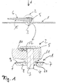
- Figure 1 is one, especially for use in motor vehicles provided, analog display instrument with a circular in this case.
- the pointer 2 is around a pointer shaft 3rd pivotable, which is passed through a bore 4 in the instrument panel 1.
- the head of the pointer shaft 3 is covered with an opaque cover 5.
- the pointer flag 6 is by means of a light source serving electroluminescent film 7 illuminated in the transmitted light process, such as is explained below with reference to the detail shown in FIG. 1 below.
- the dashboard 1 has multiple layers is constructed.
- the EL film 7 is on a solid carrier plate 8 made of plastic applied and covered with a display panel 9 designed as a film, so that no light from the EL film can get into the eye of the beholder.
- a display panel 9 designed as a film, so that no light from the EL film can get into the eye of the beholder.
- Around the Breakthrough 4 of the pointer shaft 3 is a circular opening from the display panel 9 10 cut into the display panel 9 so that light 11 of the EL film can exit.
- the light is parallel to Pointer shaft 3 in the body of the transparent pointer 1 and a Reflection surface 12, which is arranged in the pointer flag, in the direction of The tip of the pointer reflects (rays 14). Both the opening 10 and the Reflection surface 12 are covered by the cover 5, so that this is parallel to Pointer wave radiating light cannot get to the eye of the beholder.
- the cover 5 covers the cover 5, so that this is parallel to Pointer wave radiating light cannot get to the eye of the beholder.
- Around To ensure a uniform illumination of the pointer flag 6 is the Lower edge 15 of the pointer flag 6 beveled towards the tip and roughened so that the light rays 14 running parallel to the pointer flag 6 toward the viewer scatters.
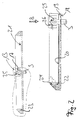
- the exemplary embodiment according to FIG. 2 shows an illuminated by the incident light method Pointer 13 shown in cross section.
- the pointer 13 is on a pointer shaft 16 stored and covered in the area of the head by a cap 17.
- the pointer 13 in turn sweeps a dashboard 21 with part-circular Display area, the shaft of the pointer being arranged in the center of the circle.
- the dashboard 21 has an EL film 19 glued onto a carrier plate 18 on, the EL film 19 being covered over a large area by a display panel 20.
- the Scoreboard 20 are the scales, symbols and others to be illuminated Except labels.
- Coupled-out light 22 is on a reflection surface arranged in the light guide 23 24 steered in the direction of the pointer 13.
- the reflective surface 24 is in this case an outer side surface inclined at an angle of 45 ° with its Ring-shaped light guide placed on the EL film.
- the pointer flag in turn has an at least partially facing the viewer reflective top surface 25, which is illuminated by the light 22 and Light rays 26 reflected towards the viewer, so that the pointer flag for the The viewer seems homogeneously illuminated.
- the top surface is approximately at an angle of 45 ° inclined to the direction of view of the viewer (arrow B) in this embodiment the pointer 13 along the pointer flag two at an angle of 90 ° to each other reflective top surfaces 25 with pointed gables.
- the pointer is in this Embodiment in the plane of the top surfaces 25 of that through the light guide 23 illuminates reflected light parallel to the display panel 20.
Landscapes
- Physics & Mathematics (AREA)
- General Physics & Mathematics (AREA)
- Engineering & Computer Science (AREA)
- Mechanical Engineering (AREA)
- Details Of Measuring Devices (AREA)
Abstract
Description
- Figur 1
- eine in Durchlichtverfahren beleuchtete Zeigerfahne und
- Figur 2
- eine in Auflichtverfahren beleuchtete Zeigerfahne.
Claims (14)
- Analoganzeigeinstrument, insbesondere für den Einsatz in Kraftfahrzeugen, mit einer Armaturentafel (1,21) und mit einem in Blickrichtung des Betrachters vor der Armaturentafel (1,21) angeordneten Zeiger (2,13), der eine wenigstens teilweise von einer Lichtquelle beleuchtbare Zeigerfahne (6) aufweist,
dadurch gekennzeichnet, daß die Lichtquelle eine Elektroluminiszenz-Folie (EL-Folie) (7,19) ist. - Instrument nach Anspruch 1,
dadurch gekennzeichnet, daß die EL-Folie (7,19) hinter einer Anzeigetafel (9,20) angeordnet ist, welche die zum Betrachter gewandte Oberfläche der Armaturentafel (1,21) bildet und auf der beleuchtbare Informationsanzeigen angeordnet sind. - Instrument nach Anspruch 1,
dadurch gekennzeichnet, daß die EL-Folie (7,19) mit einer undurchsichtigen Folie bedruckt ist, aus der die Informationsanzeigen ausgenommen sind. - Instrument nach einem der vorherigen Ansprüche,
dadurch gekennzeichnet, daß die EL-Folie (7,19) auf eine Trägerplatte (8,18) aufgebracht, insbesondere aufgeklebt, ist. - Instrument nach einem der vorherigen Ansprüche,
dadurch gekennzeichnet, daß die Anzeigetafel (9,20) die mit EL-Folie (7,19) versehene Trägerplatte (8,18) bedeckt und von unbedeckten Stellen (10) der EL-Folie (7,19) Licht zur Beleuchtung des Zeigers (2,13) ausgekoppelbar ist. - Instrument nach einem der vorherigen Ansprüche,
gekennzeichnet durch einen kreisförmigen oder teilkreisförmigen Anzeigebereich und einen verschwenkbaren Zeiger (2,13), wobei die Welle (3) des Zeigers im Zentrum des Kreises angeordnet ist. - Instrument nach einem der vorherigen Ansprüche,
dadurch gekennzeichnet, daß die Zeigerfahne aus transparentem Kunststoff ist. - Instrument nach einem der vorherigen Ansprüche,
dadurch gekennzeichnet, daß das aus der EL-Folie (7,19) ausgekoppelte Licht (11,22) in den Zeiger einkoppelbar ist. - Instrument nach Anspruch 8,
dadurch gekennzeichnet, daß das Licht (11) in den Fuß des Zeigers parallel zur Welle (3) einkoppelbar und mittels einer im Zeiger angeordneten Reflektionsfläche (12) in Richtung der Zeigerfahne (6) umlenkbar ist. - Instrument nach Anspruch 9,
dadurch gekennzeichnet, daß in die Zeigerfahne (6) Reflexionsmittel (15) eingebracht sind, welche das Licht (14) aus der Zeigerfahne (6) zum Betrachter hin reflektieren, so daß die Zeigerfahne (6) für den Betrachter homogen ausgeleuchtet scheint. - Zeigerinstrument nach einem der vorigen Ansprüche,
dadurch gekennzeichnet, daß die Zeigerfahne zumindest teilweise eine dem Betrachter zugewandte reflektierende Deckfläche (25) aufweist, die von dem Licht (22) der EL-Folie (19) beleuchtbar ist, so daß die Zeigerfahne für den Betrachter homogen erleuchtet scheint. - Zeigerinstrument nach Anspruch 11,
dadurch gekennzeichnet, daß die Deckfläche eine im Winkel von 45° zur Drehebene des Zeigers angeordnete Reflexionsfläche aufweist. - Zeigerinstrument nach einem der Ansprüche 11 oder 12,
dadurch gekennzeichnet, daß zur Auskoppelung von Licht ein Lichtleiter (23) auf die EL-Folie (19) aufgesetzt ist, mit dem die Deckfläche (25) beleuchtbar ist. - Zeigerinstrument nach einem der vorherigen Ansprüche,
dadurch gekennzeichnet, daß der Lichtleiter (23) ein zur Welle (3) des Zeigers (13) konzentrisch angeordneter Ring aus Plexiglas ist, der mit einer planen Grundfläche auf die EL-Folie (19) aufgesetzt ist und der eine unter einem Winkel von 45° geneigte äußere Seitenfläche (24) aufweist, mittels der das Licht (22) zur Deckfläche (25) der Zeigerfahne reflektierbar ist.
Applications Claiming Priority (2)
| Application Number | Priority Date | Filing Date | Title |
|---|---|---|---|
| DE10006058A DE10006058A1 (de) | 2000-02-10 | 2000-02-10 | Elektrolumineszenz-Folie zur Zeigerausleuchtung |
| DE10006058 | 2000-02-10 |
Publications (2)
| Publication Number | Publication Date |
|---|---|
| EP1124113A2 true EP1124113A2 (de) | 2001-08-16 |
| EP1124113A3 EP1124113A3 (de) | 2002-01-09 |
Family
ID=7630565
Family Applications (1)
| Application Number | Title | Priority Date | Filing Date |
|---|---|---|---|
| EP01103051A Withdrawn EP1124113A3 (de) | 2000-02-10 | 2001-02-09 | Elektrolumineszenz-Folie zur Zeigerausleuchtung |
Country Status (2)
| Country | Link |
|---|---|
| EP (1) | EP1124113A3 (de) |
| DE (1) | DE10006058A1 (de) |
Family Cites Families (9)
| Publication number | Priority date | Publication date | Assignee | Title |
|---|---|---|---|---|
| US4297681A (en) * | 1980-08-11 | 1981-10-27 | Dircksen Arnold D | Electroluminescent ring light adapter for aircraft instruments |
| US4559582A (en) * | 1984-09-04 | 1985-12-17 | Allied Corporation | Indicator illuminated with electroluminescent lighting |
| US4959759A (en) * | 1989-08-04 | 1990-09-25 | Delco Electronics Corporation | Automotive instrument display having a thickfilm electroluminescent lightpipe pointer |
| US5142274A (en) * | 1989-08-24 | 1992-08-25 | Delco Electronics Corporation | Silhouette illuminated vehicle head-up display apparatus |
| JPH0810780Y2 (ja) * | 1990-06-29 | 1996-03-29 | 矢崎総業株式会社 | 自動車用計器 |
| JP3733628B2 (ja) * | 1995-11-28 | 2006-01-11 | 株式会社デンソー | 車両用表示装置 |
| JP3189736B2 (ja) * | 1996-07-26 | 2001-07-16 | 株式会社デンソー | 複合表示装置 |
| EP1018121A1 (de) * | 1997-09-24 | 2000-07-12 | Ju, Jong-Chuel | Zeigerinstrument für ein fahrzeug |
| DE29816517U1 (de) * | 1998-09-15 | 1998-12-10 | Moser, Helmut, Dipl.-Volkswirt, 76646 Bruchsal | Leuchtanzeigeeinrichtung auf der Basis der Elektrolumineszenz ohne Mechanik mit elektronischer Ansteuerung |
-
2000
- 2000-02-10 DE DE10006058A patent/DE10006058A1/de not_active Withdrawn
-
2001
- 2001-02-09 EP EP01103051A patent/EP1124113A3/de not_active Withdrawn
Also Published As
| Publication number | Publication date |
|---|---|
| EP1124113A3 (de) | 2002-01-09 |
| DE10006058A1 (de) | 2001-08-16 |
Similar Documents
| Publication | Publication Date | Title |
|---|---|---|
| DE3817874C2 (de) | Meßgerät | |
| DE68909765T2 (de) | Beleuchtete Anzeigetafel. | |
| EP1015269B1 (de) | Anzeigevorrichtung | |
| DE2536700C3 (de) | Einrichtung zum Anzeigen von Fehlfunktionen einer Anlage | |
| EP0967464B1 (de) | Zeigerinstrument | |
| DE3625767A1 (de) | Lichtdiffusionsvorrichtung mit rueckstrahler | |
| DE19547375A1 (de) | Anzeigeeinrichtung | |
| DE19632381A1 (de) | Kombinationsinstrument | |
| EP1010969B1 (de) | Zeigerinstrument | |
| DE3834757A1 (de) | Messgeraet-leuchtanzeigeskalenanordnung | |
| DE19844316A1 (de) | Beleuchtbare Anzeigeskalenvorrichtung | |
| DE69911567T2 (de) | Beleuchtbares Zeigerinstrument | |
| DE102010026773A1 (de) | Skalenelement für ein Anzeigeinstrument, Kombiinstrument und Fahrzeug mit einem Skalenelement | |
| DE10102774A1 (de) | Anzeigevorrichtung, insbesondere für ein Fahrzeug | |
| EP1106419B1 (de) | Bediengerät mit beleuchtbaren Bedienelementen | |
| EP1034965B1 (de) | Anzeigeeinheit mit einer Anzeigenfront und Verfahren zur Herstellung einer solchen Anzeigenfront | |
| DE102010035717B4 (de) | Anzeigevorrichtung für ein Kraftfahrzeug und Kraftfahrzeug | |
| DE102010032946A1 (de) | Kraftfahrzeug mit einem Innenraum, in dem eine Beleuchtungseinrichtung angeordnet ist | |
| DE102008052420B4 (de) | Anzeigevorrichtung für ein Fahrzeug | |
| EP1113246A2 (de) | Anordnung zum Ausleuchten einer Anzeigevorrichtung mit einem Zifferblatt | |
| DE102012016771A1 (de) | Instrument mit Ziffernblatt für ein Kraftfahrzeug und Verfahren zur Herstellung desselben | |
| DE3113773C2 (de) | ||
| EP1124113A2 (de) | Elektrolumineszenz-Folie zur Zeigerausleuchtung | |
| DE102022127222A1 (de) | Beleuchtungsvorrichtung für Fahrzeuge | |
| DE4244452A1 (de) | Anzeigeinstrument für Kraftfahrzeuge |
Legal Events
| Date | Code | Title | Description |
|---|---|---|---|
| PUAI | Public reference made under article 153(3) epc to a published international application that has entered the european phase |
Free format text: ORIGINAL CODE: 0009012 |
|
| AK | Designated contracting states |
Kind code of ref document: A2 Designated state(s): AT BE CH CY DE DK ES FI FR GB GR IE IT LI LU MC NL PT SE TR Kind code of ref document: A2 Designated state(s): DE FR GB IT |
|
| AX | Request for extension of the european patent |
Free format text: AL;LT;LV;MK;RO;SI |
|
| PUAL | Search report despatched |
Free format text: ORIGINAL CODE: 0009013 |
|
| AK | Designated contracting states |
Kind code of ref document: A3 Designated state(s): AT BE CH CY DE DK ES FI FR GB GR IE IT LI LU MC NL PT SE TR |
|
| AX | Request for extension of the european patent |
Free format text: AL;LT;LV;MK;RO;SI |
|
| 17P | Request for examination filed |
Effective date: 20020628 |
|
| AKX | Designation fees paid |
Free format text: DE FR GB IT |
|
| RAP1 | Party data changed (applicant data changed or rights of an application transferred) |
Owner name: JOHNSON CONTROLS AUTOMOTIVE ELECTRONICS GMBH |
|
| 17Q | First examination report despatched |
Effective date: 20080422 |
|
| STAA | Information on the status of an ep patent application or granted ep patent |
Free format text: STATUS: THE APPLICATION IS DEEMED TO BE WITHDRAWN |
|
| 18D | Application deemed to be withdrawn |
Effective date: 20141022 |