EP1123831A1 - Headrest for vehicle seats - Google Patents
Headrest for vehicle seats Download PDFInfo
- Publication number
- EP1123831A1 EP1123831A1 EP00125896A EP00125896A EP1123831A1 EP 1123831 A1 EP1123831 A1 EP 1123831A1 EP 00125896 A EP00125896 A EP 00125896A EP 00125896 A EP00125896 A EP 00125896A EP 1123831 A1 EP1123831 A1 EP 1123831A1
- Authority
- EP
- European Patent Office
- Prior art keywords
- headrest according
- headrest
- force application
- support rod
- support
- Prior art date
- Legal status (The legal status is an assumption and is not a legal conclusion. Google has not performed a legal analysis and makes no representation as to the accuracy of the status listed.)
- Granted
Links
- 210000001520 comb Anatomy 0.000 claims description 3
- 239000012530 fluid Substances 0.000 claims 1
- 230000002787 reinforcement Effects 0.000 claims 1
- 230000002441 reversible effect Effects 0.000 description 4
- 230000003014 reinforcing effect Effects 0.000 description 3
- 230000001447 compensatory effect Effects 0.000 description 1
- 238000003780 insertion Methods 0.000 description 1
- 230000037431 insertion Effects 0.000 description 1
Images


Classifications
-
- B—PERFORMING OPERATIONS; TRANSPORTING
- B60—VEHICLES IN GENERAL
- B60N—SEATS SPECIALLY ADAPTED FOR VEHICLES; VEHICLE PASSENGER ACCOMMODATION NOT OTHERWISE PROVIDED FOR
- B60N2/00—Seats specially adapted for vehicles; Arrangement or mounting of seats in vehicles
- B60N2/02—Seats specially adapted for vehicles; Arrangement or mounting of seats in vehicles the seat or part thereof being movable, e.g. adjustable
- B60N2/0224—Non-manual adjustments, e.g. with electrical operation
- B60N2/02246—Electric motors therefor
-
- B—PERFORMING OPERATIONS; TRANSPORTING
- B60—VEHICLES IN GENERAL
- B60N—SEATS SPECIALLY ADAPTED FOR VEHICLES; VEHICLE PASSENGER ACCOMMODATION NOT OTHERWISE PROVIDED FOR
- B60N2/00—Seats specially adapted for vehicles; Arrangement or mounting of seats in vehicles
- B60N2/80—Head-rests
- B60N2/806—Head-rests movable or adjustable
- B60N2/809—Head-rests movable or adjustable vertically slidable
- B60N2/812—Head-rests movable or adjustable vertically slidable characterised by their locking devices
- B60N2/818—Head-rests movable or adjustable vertically slidable characterised by their locking devices with stepwise positioning
-
- B—PERFORMING OPERATIONS; TRANSPORTING
- B60—VEHICLES IN GENERAL
- B60N—SEATS SPECIALLY ADAPTED FOR VEHICLES; VEHICLE PASSENGER ACCOMMODATION NOT OTHERWISE PROVIDED FOR
- B60N2/00—Seats specially adapted for vehicles; Arrangement or mounting of seats in vehicles
- B60N2/80—Head-rests
- B60N2/894—Head-rests with rods solidly attached to the back-rest
Definitions
- the invention relates to a headrest for vehicle seats accordingly the preamble of claim 1.
- a headrest is in DE 35 19 351 C2.
- the headrest according to DE 35 19 351 C2 is an electromotive Drive unit in the lower frame web of a frame-shaped headrest support built-in.
- Each tooth of a row of teeth on the support rod therefore forms for the drive element an abutment on the support rod side.
- the head cushion support known headrest can be adjusted up or down.
- the known headrest according to DE 35 19 351 C2 belongs to the genus of the headrests adjustable in height, which - in contrast to the Height-adjustable headrests on the backrest - the height adjustment movement the headrest by a relative movement between the seat back Support rods and the headrest support relatively movable to the latter he follows.
- the headrest described in DE 35 19 351 C2 is concerned is a specially designed headrest, in which both the actual Headrest elements as well as the motor drive unit with their Drive elements are specially matched to each other and thus an individual, form a largely integrated unit.
- the invention has for its object to provide a headrest whose motor drive unit a compact design and also versatile Possible applications regarding the height adjustment of a headrest allowed.
- this object is shared with the Features of the preamble of claim 1 solved in that the motor Drive unit with respect to both the support rod and the Head cushion carrier is guided in a relatively movable, height-adjustable manner, that of the motor drive unit two height adjustable opposite to each other Movable drive elements, of which the first drive element at least indirectly with a force application point facing away from the drive unit on the support rod and the second drive element with one of the drive unit away from the force application point at least indirectly on the headrest support are supported.
- the drive unit according to the invention forms one of the individual ones special design of a headrest (see. DE 35 19 351 C2) largely independent compact independent assembly, its drive elements in different ways on those to be moved relative to each other Components of a headrest, namely on the support rod or on the support rods and can attack the headrest support.
- the independence of the drive unit according to the invention is also due to the fact that the latter both with respect to the support rod and is relatively adjustable in height with respect to the headrest support.
- Each of the two drive elements can be both tensile and and pressure-resistant with respect to the corresponding headrest component, that is with respect to the support rod or with respect to the headrest support his.
- An embodiment of the invention is that the Force application point of the first drive element at least indirectly only pressure-resistant on the support rod and the force application point of the second drive element at least indirectly also only pressure-resistant on the head cushion support are supported.
- This embodiment allows in particular in connection with a rear headrest has the following advantage: in the event that a rear headrest assumes their maximum altitude and thereby e.g. the rear view of the Driver hindered, the two drive elements are extended, whereby one drive element on the top of the support rod and the other drive element supported only pressure-resistant at the bottom of the headrest support. While the two drive elements, so to speak, starting from the drive unit spread apart, the headrest carrier will be in its lowest Position adjusted downwards.
- the drive unit is either on the side of the support rod or on the headrest support is relatively movable adjustable in height, it does not matter in which individual starting altitude, the drive unit is because the Force application points of the two drive elements each independently to the corresponding one support rod side or head cushion support side abutment points get, especially since the drive unit any height differences can correct by an adjustment movement.
- Another embodiment of the invention e.g. in connection with rear headrests the same handling as described above allowed, according to the invention is that the force application point of the first drive element at least indirectly tensile and compressive or only pressure-resistant on the support rod and the force application point of the second drive element at least indirectly only pressure-resistant or tensile and pressure-resistant on the head cushion support are supported.
- the force application point of the first Drive elements are tensile and pressure resistant on the support rod and the force application point of the second drive element is supported only pressure-resistant on the head cushion support his.
- the motor drive unit Tension and pressure resistant via the force application point of the first drive element held on the support rod.
- an embodiment of a headrest according to the invention characterized in that the force application point of the first Drive elements at least indirectly tensile and pressure resistant on the support rod and the force application point of the second drive element at least indirectly can also be supported in a tensile and compressive manner on the head cushion support.
- this Embodiment according to the invention is the height adjustment of the headrest support motorized in both directions.
- each drive element is a rack of the rack and pinion gear trained drive unit.
- Another embodiment of a drive unit to a special The invention has a compact and low design with a large adjustment range created in that the drive unit is a motor-driven pinion has, which together with at two opposite circumferential points the two designed as racks and parallel to each other arranged drive elements combs.
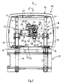
- the headrest 10 has a head cushion support 11, which with a Head cushion 12 is clothed.
- a Head cushion 12 is clothed.
- the head cushion support 11 For sliding guidance and gradual height adjustment is the head cushion support 11 with two sliding sleeves 13 held on it provided, which carry detent springs 14, which are approximately tangential or secantial to the support rods 16 extending latch legs 15 with notches 17th interact adjustably lockable on the lateral surface of the support rods 16.
- the downward insertion regions 18 of the two support rods 16 are locked in insert sleeves 19 so that they cannot be removed.
- the insert sleeves 19 are plugged into the partially shown seat back frame 20.
- the upper ends 21 of the two support rods 16 are by means of a Yokes 22 rigidly connected.
- the notches 17 are formally designed and act in such a way with the Locking legs 15 of the locking springs 14 together that an adjustment of the Head cushion support 11 in the y direction, that is to say in the high position, relatively light and in opposite direction z, i.e. towards the low position, is more difficult.
- a motor drive unit 25 is accommodated, which is constructed as follows: in a housing 26 there is a Electric motor (DC motor) 27, the motor shaft 28 via a screw 29 drives a worm wheel 30, which has several gear wheels (binding wheels) is geared with a pinion 31, which at the same time with the rows of teeth 32, 33 of a first rack A1 and a second rack A2 combs.
- DC motor Electric motor
- worm wheel 30 which has several gear wheels (binding wheels) is geared with a pinion 31, which at the same time with the rows of teeth 32, 33 of a first rack A1 and a second rack A2 combs.
- the electric motor 27 is reversible, i.e. in terms of its direction of rotation reversible.
- the force application point K1 of the first rack A1 is by means of a Fastening tab arrangement 34 connected to the yoke 22 in a tensile and compressive manner.
- the force application point K2 of the second rack A2 is only supported pressure-resistant on reinforcing ribs 35, which in the region of the bottom 24 of the Head cushion support 11 are provided.
- the drive unit 25 is only attached to the yoke 22 in the area of its force application point K1, that is to a certain extent "hangs" on yoke 22.
- the headrest 10 shown in FIGS. 1-3 works as follows:
- the electric motor 27 is equipped with such Direction of rotation switched on so that the racks A1 and A2 from the Stand out housing 26 of the drive unit 25. That moves Housing 26 in the direction z down, as well as with its force application point K2 on the bottom reinforcing ribs 35 of the headrest support 11 only pressure-resistant second rack A2.
- the head cushion carrier has itself 11 moved into its low position.
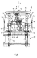
- the second embodiment of a headrest 10 according to FIGS. 4 and 5 differs from the first embodiment according to FIGS. 1-3 in that the housing 26 forms a cross member 36, which on both of them Each end has a guide area encompassing a support rod 16, specifically has a sliding guide area 37.
- the two force application points K1 and K2 are only pressure-resistant on the yoke 22 or on the bottom reinforcing ribs 35 of the headrest support 11 supportable.
- the third embodiment shown in FIG. 6 differs from the first embodiment shown in FIGS. 1 to 3 only by that in addition to the force application point K1 also the force application point K2 second rack A2 by means of a mounting bracket arrangement 38 the bottom 24 of the head cushion support 11 is connected in a tensile and compressive manner.
- both force application points K1 and K2 of the racks A1 and A2 for one with the yoke 22 and the other with the bottom 24 of the headrest support 11 are connected tensile and pressure resistant, can be reversible Operation of the electric motor 27 of the head cushion support 11 upwards in the direction y or can be adjusted downwards in the direction z.
- a stepless height adjustment is also conceivable, especially since it is a relatively large one Worm gears 29, 30 of the drive unit 25 that cause self-locking the head cushion support 11 is adequately locked in practically any height.
- the electrical equipment can be chosen so that each time it is reached the high or low position of the head cushion support 11 a limit switch takes place, possibly connected with a switch in the other direction of rotation.
Abstract
Description
Die Erfindung betrifft eine Kopfstütze für Fahrzeugsitze entsprechend dem Oberbegriff des Anspruchs 1. Eine solche Kopfstütze ist in der DE 35 19 351 C2 beschrieben.The invention relates to a headrest for vehicle seats accordingly the preamble of claim 1. Such a headrest is in DE 35 19 351 C2.
Bei der Kopfstütze gemäß der DE 35 19 351 C2 ist eine elektromotorische Antriebseinheit im unteren Rahmensteg eines rahmenförmigen Kopfpolsterträgers eingebaut. Aus beiden Stirnseiten der Antriebseinheit tritt je ein Antriebselement in Form einer Antriebswelle aus, welche endständig ein Ritzel trägt, das jeweils mit einer als Zahnstange ausgebildeten Tragstange kämmt. Jeder Zahn einer tragstangenseitigen Zahnreihe bildet daher für das Antriebselement ein tragstangenseitiges Widerlager. Je nach Drehrichtung der beiden gleichsinnig umlaufenden Antriebswellen kann der Kopfpolsterträger der bekannten Kopfstütze nach oben oder nach unten verstellt werden.In the headrest according to DE 35 19 351 C2 is an electromotive Drive unit in the lower frame web of a frame-shaped headrest support built-in. One enters from both ends of the drive unit Drive element in the form of a drive shaft, which is a pinion carries, which meshes with a rack designed as a rack. Each tooth of a row of teeth on the support rod therefore forms for the drive element an abutment on the support rod side. Depending on the direction of rotation of the two In the same direction revolving drive shafts, the head cushion support known headrest can be adjusted up or down.
Die bekannte Kopfstütze gemäß der DE 35 19 351 C2 zählt zur Gattung
der innenhöhenverstellbaren Kopfstützen, bei denen - im Unterschied zu den
sitzlehnenseitig höhenverstellbaren Kopfstützen - die Höhenverstellbewegung
der Kopfstütze durch eine Relativbewegung zwischen den sitzlehnenseitig festgelegten
Tragstangen und dem zu letzteren relativbeweglichen Kopfpolsterträger
erfolgt.The known headrest according to
Bei der in der DE 35 19 351 C2 beschriebenen Kopfstütze handelt es
sich um eine speziell ausgestaltete Kopfstütze, bei welcher sowohl die eigentlichen
Kopfstützenelemente als auch die motorische Antriebseinheit mit ihren
Antriebselementen besonders aufeinander abgestimmt sind und so eine individuelle,
weitestgehend integrierte Baueinheit bilden.The headrest described in
Ausgehend von der durch die DE 35 19 351 C2 bekannten Kopfstütze,
liegt der Erfindung die Aufgabe zugrunde, eine Kopfstütze zu schaffen, deren
motorische Antriebseinheit eine kompakte Bauform und außerdem vielfältige
Anwendungsmöglichkeiten bezüglich der Höhenverstellung einer Kopfstütze
gestattet.Starting from the headrest known from
Entsprechend der Erfindung wird diese Aufgabe gemeinsam mit den Merkmalen des Oberbegriffs des Anspruchs 1 dadurch gelöst, dass die motorische Antriebseinheit sowohl bezüglich der Tragstange als auch bezüglich des Kopfpolsterträgers relativbeweglich höhenverstellbar geführt ist, dass von der motorischen Antriebseinheit zwei entgegengesetzt zueinander höhenverstellbar bewegliche Antriebselemente ausgehen, von denen das erste Antriebselement mit einer der Antriebseinheit abgewandten Kraftangriffsstelle mindestens mittelbar an der Tragstange und das zweite Antriebselement mit einer der Antriebseinheit abgewandten Kraftangriffsstelle mindestens mittelbar am Kopfpolsterträger abstützbar sind.According to the invention, this object is shared with the Features of the preamble of claim 1 solved in that the motor Drive unit with respect to both the support rod and the Head cushion carrier is guided in a relatively movable, height-adjustable manner, that of the motor drive unit two height adjustable opposite to each other Movable drive elements, of which the first drive element at least indirectly with a force application point facing away from the drive unit on the support rod and the second drive element with one of the drive unit away from the force application point at least indirectly on the headrest support are supported.
Die erfindungsgemäße Antriebseinheit bildet eine von der individuellen
speziellen Bauform einer Kopfstütze (vgl. dazu DE 35 19 351 C2) weitestgehend
unabhängige kompakte eigenständige Baugruppe, deren Antriebselemente
auf unterschiedliche Weise an den relativ zueinander zu bewegenden
Bauteilen einer Kopfstütze, nämlich an der Tragstange oder an den Tragstangen
und an dem Kopfpolsterträger, angreifen können. The drive unit according to the invention forms one of the individual ones
special design of a headrest (see.
Die Unabhängigkeit der erfindungsgemäßen Antriebseinheit ist zudem dadurch bedingt, dass letztere sowohl bezüglich der Tragstange als auch bezüglich des Kopfpolsterträgers relativbeweglich höhenverstellbar geführt ist.The independence of the drive unit according to the invention is also due to the fact that the latter both with respect to the support rod and is relatively adjustable in height with respect to the headrest support.
Jedes der beiden Antriebselemente kann sowohl zugfest als auch zug- und druckfest bezüglich des korrespondierenden Kopfstützen-Bauteils, also bezüglich der Tragstange oder bezüglich des Kopfpolsterträgers, angeordnet sein.Each of the two drive elements can be both tensile and and pressure-resistant with respect to the corresponding headrest component, that is with respect to the support rod or with respect to the headrest support his.
Dadurch, dass die beiden Antriebselemente entgegengesetzt zueinander höhenverstellbar sind, ist außerdem die Voraussetzung zu einer niedrig bauenden Antriebseinheit geschaffen worden, die zugleich einen großen Verstellweg gestattet.The fact that the two drive elements oppose each other are adjustable in height, is also the prerequisite for a low building Drive unit has been created, which also has a large adjustment range allowed.
Eine erfindungsgemäße Ausführungsform besteht darin, dass die Kraftangriffsstelle des ersten Antriebselements mindestens mittelbar nur druckfest an der Tragstange und die Kraftangriffsstelle des zweiten Antriebselements mindestens mittelbar ebenfalls nur druckfest am Kopfpolsterträger abstützbar sind.An embodiment of the invention is that the Force application point of the first drive element at least indirectly only pressure-resistant on the support rod and the force application point of the second drive element at least indirectly also only pressure-resistant on the head cushion support are supported.
Diese Ausführungsform gestattet insbesondere im Zusammenhang mit einer Fondkopfstütze folgenden Vorteil: für den Fall, dass eine Fondkopfstütze ihre maximale Höhenlage einnimmt und dabei z.B. die rückwärtige Sicht des Fahrers behindert, werden die beiden Antriebselemente ausgefahren, wobei sich ein Antriebselement oben tragstangenseitig und das andere Antriebselement unten am Kopfpolsterträger jeweils nur druckfest abstützt. Während sich die beiden Antriebselemente, ausgehend von der Antriebseinheit, gewissermaßen auseinanderspreizen, wird der Kopfpolsterträger in seine niedrigste Position nach unten verstellt.This embodiment allows in particular in connection with a rear headrest has the following advantage: in the event that a rear headrest assumes their maximum altitude and thereby e.g. the rear view of the Driver hindered, the two drive elements are extended, whereby one drive element on the top of the support rod and the other drive element supported only pressure-resistant at the bottom of the headrest support. While the two drive elements, so to speak, starting from the drive unit spread apart, the headrest carrier will be in its lowest Position adjusted downwards.
Da die Antriebseinheit entweder tragstangenseitig oder am Kopfpolsterträger relativ beweglich höhenverstellbar geführt ist, ist es gleichgültig, in welcher individuellen Ausgangs-Höhenlage sich die Antriebseinheit befindet, da die Kraftangriffsstellen der beiden Antriebselemente jeweils selbständig zu den korrespondierenden tragstangenseitigen oder kopfpolsterträgerseitigen Widerlagerstellen gelangen, zumal die Antriebseinheit etwaige Höhenunterschiede durch eine Anpassungsbewegung korrigieren kann.Since the drive unit is either on the side of the support rod or on the headrest support is relatively movable adjustable in height, it does not matter in which individual starting altitude, the drive unit is because the Force application points of the two drive elements each independently to the corresponding one support rod side or head cushion support side abutment points get, especially since the drive unit any height differences can correct by an adjustment movement.
Ein erneutes Verschieben der Kopfstütze in die Höhenlage hinein geschieht bei der vorbeschriebenen erfindungsgemäßen Ausführungsform zweckmäßig derart, dass zunächst die beiden Antriebselemente selbsttätig eingefahren werden, worauf eine ungehinderte Verstellung der Kopfstütze nach oben von Hand erfolgen kann.Another move of the headrest into the higher position happens in the embodiment of the invention described above Expediently such that the two drive elements are first retracted automatically be followed by an unimpeded adjustment of the headrest can be done by hand above.
Eine andere erfindungsgemäße Ausführungsform, welche z.B. in Verbindung mit Fondkopfstützen dieselbe vorbeschriebene Handhabungsweise gestattet, besteht entsprechend der Erfindung darin, dass die Kraftangriffsstelle des ersten Antriebselements mindestens mittelbar zug- und druckfest oder nur druckfest an der Tragstange und die Kraftangriffsstelle des zweiten Antriebselements mindestens mittelbar nur druckfest oder zug- und druckfest am Kopfpolsterträger abstützbar sind.Another embodiment of the invention, e.g. in connection with rear headrests the same handling as described above allowed, according to the invention is that the force application point of the first drive element at least indirectly tensile and compressive or only pressure-resistant on the support rod and the force application point of the second drive element at least indirectly only pressure-resistant or tensile and pressure-resistant on the head cushion support are supported.
Demnach können beispielsweise die Kraftangriffsstelle des ersten Antriebselements zug- und druckfest an der Tragstange und die Kraftangriffsstelle des zweiten Antriebselements nur druckfest am Kopfpolsterträger abgestützt sein. Bei einer solchen Ausführungsform ist die motorische Antriebseinheit über die Kraftangriffsstelle des ersten Antriebselements zug- und druckfest an der Tragstange gehalten. Dies hat den Vorteil, dass die motorische Antriebseinheit sich während ihrer Höhenverstellung am ersten Antriebselement führen kann, so dass keine weiteren Mittel zur Führung der Antriebseinheit bezüglich der Tragstange bzw. bezüglich des Kopfpolsterträgers erforderlich sind.Accordingly, for example, the force application point of the first Drive elements are tensile and pressure resistant on the support rod and the force application point of the second drive element is supported only pressure-resistant on the head cushion support his. In such an embodiment, the motor drive unit Tension and pressure resistant via the force application point of the first drive element held on the support rod. This has the advantage that the motor Drive unit during the height adjustment on the first drive element can lead so that no further means for guiding the drive unit required with respect to the support rod or with respect to the headrest support are.
Schließlich ist eine Ausführungsform einer erfindungsgemäßen Kopfstütze dadurch gekennzeichnet, dass die Kraftangriffsstelle des ersten Antriebselements mindestens mittelbar zug- und druckfest an der Tragstange und die Kraftangriffsstelle des zweiten Antriebselements mindestens mittelbar ebenfalls zug- und druckfest am Kopfpolsterträger abstützbar sind. Bei dieser erfindungsgemäßen Ausführungsform erfolgt die Höhenverstellung des Kopfpolsterträgers in beiden Richtungen motorisch.Finally, an embodiment of a headrest according to the invention characterized in that the force application point of the first Drive elements at least indirectly tensile and pressure resistant on the support rod and the force application point of the second drive element at least indirectly can also be supported in a tensile and compressive manner on the head cushion support. At this Embodiment according to the invention is the height adjustment of the headrest support motorized in both directions.
Eine von der Erfindung besonders bevorzugte Ausführungsform besteht darin, dass jedes Antriebselement eine Zahnstange der als Zahnstangengetriebe ausgebildeten Antriebseinheit ist.A particularly preferred embodiment of the invention exists in that each drive element is a rack of the rack and pinion gear trained drive unit.
Eine weitere Ausgestaltung einer Antriebseinheit zu einer besonders kompakten und niedrigen Bauform mit großem Verstellweg hat die Erfindung dadurch geschaffen, dass die Antriebseinheit ein motorisch antreibbares Ritzel aufweist, welches an zwei gegenüberliegenden Umfangsstellen gemeinsam mit den beiden als Zahnstangen ausgebildeten und im Parallelabstand zueinander angeordneten Antriebselementen kämmt. Another embodiment of a drive unit to a special The invention has a compact and low design with a large adjustment range created in that the drive unit is a motor-driven pinion has, which together with at two opposite circumferential points the two designed as racks and parallel to each other arranged drive elements combs.
In den Zeichnungen sind bevorzugte Ausführungsbeispiele entsprechend
der Erfindung dargestellt, es zeigt
In den Zeichnungen ist die jeweilige Kopfstütze unabhängig von ihrer
Ausgestaltung jeweils mit der Bezugsziffer 10 versehen. Auch sind einander
analogen Bauteilen unabhängig von ihrer besonderen Ausführungsform stets
dieselben Bezugsziffern zugeordnet.In the drawings, the respective headrest is independent of it
Design each provided with the
Die Kopfstütze 10 weist einen Kopfpolsterträger 11 auf, der mit einem
Kopfpolster 12 bekleidet ist. Zur Gleitführung und stufenweisen Höhenverstellung
ist der Kopfpolsterträger 11 mit zwei an ihm gehaltenen Gleithülsen 13
versehen, welche Rastfedern 14 tragen, deren sich etwa tangential bzw. sekantial
zu den Tragstangen 16 erstreckende Rastschenkel 15 mit Rastkerben 17
an der Mantelfläche der Tragstangen 16 verstellarretierbar zusammenwirken.The
Die nach unten weisenden Einsteckbereiche 18 der beiden Tragstangen
16 sind in Einsteckhülsen 19 unverschieblich herausnehmbar arretiert. Die Einsteckhülsen
19 sind in dem teilweise dargestellten Sitzlehnenrahmen 20 steckverrastet.The
Die oberen Enden 21 der beiden Tragstangen 16 sind mittels eines
Jochs 22 starr miteinander verbunden.The
Die Rastkerben 17 sind formlich so gestaltet und wirken derart mit den
Rastschenkeln 15 der Rastfedern 14 zusammen, dass eine Verstellung des
Kopfpolsterträgers 11 in Richtung y, also zur Hochlage hin, relativ leicht und in
entgegengesetzter Richtung z, also zur Tieflage hin, schwergängiger erfolgt.The
Innerhalb des Kopfpolsterträgers 11, und zwar innerhalb des von den
beiden Tragstangen 16, dem Joch 22 und dem Boden 24 des Kopfpolsterträgers
11 umgrenzten Raumes 23, ist eine motorische Antriebseinheit 25 aufgenommen,
welche wie folgt aufgebaut ist: in einem Gehäuse 26 befindet sich ein
Elektromotor (Gleichstrommotor) 27, dessen Motorwelle 28 über eine Schnecke
29 ein Schneckerad 30 treibt, welches über mehrere Zahnräder (Binderäder)
mit einem Ritzel 31 getrieblich verbunden ist, welches zugleich mit den Zahnreihen
32, 33 einer ersten Zahnstange A1 und einer zweiten Zahnstange A2
kämmt. Within the
Der Elektromotor 27 ist reversierbar, d.h. hinsichtlich seiner Drehrichtung
umkehrbar. Die Kraftangriffsstelle K1 der ersten Zahnstange A1 ist mittels einer
Befestigungslaschenanordnung 34 zug- und druckfest mit dem Joch 22 verbunden.The
Die Kraftangriffsstelle K2 der zweiten Zahnstange A2 stützt sich lediglich
druckfest auf Verstärkungsrippen 35 ab, die im Bereich des Bodens 24 des
Kopfpolsterträgers 11 vorgesehen sind.The force application point K2 of the second rack A2 is only supported
pressure-resistant on reinforcing
Nach diesen Ausführungen ist vorstellbar, dass die Antriebseinheit 25
lediglich im Bereich ihrer Kraftangriffsstelle K1 am Joch 22 befestigt ist, also
gewissermaßen am Joch 22 "hängt". According to these statements, it is conceivable that the
Die in den Fig. 1-3 dargestellte Kopfstütze 10 funktioniert wie folgt:The
Wenn sich der Kopfpolsterträger 11 beispielsweise einer Fondkopfstütze
10, wie in Fig. 1 dargestellt, in seiner Hochlage befindet, dabei aber das rückwärtige
Blickfeld des Fahrers verstellt, wird der Elektromotor 27 mit einer derartigen
Drehrichtung eingeschaltet, dass die Zahnstangen A1 und A2 aus dem
Gehäuse 26 der Antriebseinheit 25 hervortreten. Dabei bewegt sich das
Gehäuse 26 in Richtung z nach unten, ebenso wie die sich mit ihrer Kraftangriffsstelle
K2 auf den bodenseitigen Verstärkungsrippen 35 des Kopfpolsterträgers
11 lediglich druckfest abstützende zweite Zahnstange A2.If the head cushion support 11, for example, a
Wie anhand von Fig. 2 zu ersehen, hat sich dabei der Kopfpolsterträger 11 in seine Tieflage hineinbewegt.As can be seen from FIG. 2, the head cushion carrier has itself 11 moved into its low position.
Sobald die Tieflage des Kopfpolsterträgers 11 erreicht ist, sorgt ein
elektrisches Rückmeldesignal der Antriebseinheit 25 selbsttätig dafür, dass der
Elektromotor 27 in seiner umgekehrten Drehrichtung aktiviert wird, worauf beide
Zahnstangen A1 und A2 in das Gehäuse 26 einfahren. Dabei "klettert" die
Antriebseinheit 25 mittels ihres Ritzels 31 gewissermaßen bis in die in Fig. 3
gezeigte angehobene Bereitstellung. Diese Bereitstellung ist Voraussetzung
dafür, dass der Kopfpolsterträger 11, sofern es von den Fond-Fahrgästen
gewünscht ist, wiederum von Hand in seine Hochlage gemäß Fig. 1 verstellt
werden kann.As soon as the low position of the
Die zweite Ausführungsform einer Kopfstütze 10 gemäß den Fig. 4 und 5
unterscheidet sich von der ersten Ausführungsform gemäß den Fig. 1-3
dadurch, dass das Gehäuse 26 eine Traverse 36 bildet, welche an ihren beiden
Enden je einen eine Tragstange 16 umgreifenden Führungsbereich, und zwar
einen Gleitführungsbereich 37, aufweist.The second embodiment of a
Zudem sind die beiden Kraftangriffsstellen K1 und K2 lediglich druckfest
am Joch 22 bzw. an den bodenseitigen Verstärkungsrippen 35 des Kopfpolsterträgers
11 abstützbar.In addition, the two force application points K1 and K2 are only pressure-resistant
on the
Allein anhand von Fig. 4 ist vorstellbar, dass dank der Traverse 36 mit
den beiden Gleitführungsbereichen 37 die anfängliche Höhenlage der Antriebseinheit
25 bei Hochlage des Kopfpolsterträgers 11 (vgl. Fig. 1) beliebig sein
kann. Wenn nämlich der Elektromotor 27 so aktiviert wird, dass die erste
Zahnstange A1 in Richtung y und die zweite Zahnstange A2 in Richtung z ausfährt,
stellt sich die Tieflage gemäß Fig. 4 automatisch ein, wobei die an den
beiden Tragstangen 16 relativbeweglich höhenverstellbar geführte Antriebseinheit
25 - je nach ihrer zuvor eingenommenen Höhenposition - eine Ausgleichsbewegung
in Richtung y oder in Richtung z vollführt.4, it is conceivable that thanks to the
Sobald die Tieflage gemäß Fig. 4 erreicht ist, sorgt wiederum ein elektrisches
Rückmeldesignal der Antriebseinheit 25 dafür, dass die Bereitstellungsposition
gemäß. Fig. 5 selbsttätig herbeigeführt wird. Wenn nun der Kopfpolsterträger
11 gemäß seiner in Fig. 5 gezeigten Tieflage in seine Hochlage (vgl.
Fig. 1) versetzt werden soll, was von Hand geschieht, wird zugleich die
Antriebseinheit 25 dank der Gleitführungsbereiche 37 ihrer Traverse 36 in
Richtung y so weit nach oben verschoben, bis die Kraftangriffsstelle K1 der
ersten Zahnstange A1 von unten gegen das Joch 22 stößt.As soon as the low position according to FIG. 4 is reached, an electrical turn is provided
Feedback signal of the
Die in Fig. 6 dargestellte dritte Ausführungsform unterscheidet sich von
der in den Fig. 1 bis 3 gezeigten ersten Ausführungsform lediglich dadurch,
dass zusätzlich zur Kraftangriffsstelle K1 auch die Kraftangriffsstelle K2 der
zweiten Zahnstange A2 mittels einer Befestigungslaschenanordnung 38 mit
dem Boden 24 des Kopfpolsterträgers 11 zug- und druckfest verbunden ist.The third embodiment shown in FIG. 6 differs from
the first embodiment shown in FIGS. 1 to 3 only by
that in addition to the force application point K1 also the force application point K2
second rack A2 by means of a mounting
Da beide Kraftangriffsstellen K1 und K2 der Zahnstangen A1 und A2 zum
einen mit dem Joch 22 und zum anderen mit dem Boden 24 des Kopfpolsterträgers
11 zug- und druckfest verbunden sind, kann durch reversierbaren
Betrieb des Elektromotors 27 der Kopfpolsterträger 11 nach oben in Richtung y
oder nach unten in Richtung z verstellt werden.Since both force application points K1 and K2 of the racks A1 and A2 for
one with the
Bei Nichtvorhandensein der Rastkerben 17 ist in diesem Zusammenhang
auch eine stufenlose Höheneinstellung denkbar, zumal das eine relativ große
Selbsthemmung bedingende Schneckengetriebe 29, 30 der Antriebseinheit 25
den Kopfpolsterträger 11 praktisch in jeder Höhenlage hinreichend arretiert. Die
elektrische Ausrüstung kann dabei so gewählt sein, dass jeweils bei Erreichen
der Hochlage oder der Tieflage des Kopfpolsterträgers 11 eine Endabschaltung
erfolgt, ggf. verbunden mit einer Umschaltung in die andere Drehrichtung.In the absence of the locking
Claims (18)
Applications Claiming Priority (2)
| Application Number | Priority Date | Filing Date | Title |
|---|---|---|---|
| DE10006099A DE10006099A1 (en) | 2000-02-11 | 2000-02-11 | Head rest for car seat comprises cushioned pad mounted on carrier which can slide on vertical bars attached to seat and whose height is adjusted by motorised unit which operates hydraulic cylinder and piston units attached to bar and pad |
| DE10006099 | 2000-02-11 |
Publications (2)
| Publication Number | Publication Date |
|---|---|
| EP1123831A1 true EP1123831A1 (en) | 2001-08-16 |
| EP1123831B1 EP1123831B1 (en) | 2004-09-01 |
Family
ID=7630591
Family Applications (1)
| Application Number | Title | Priority Date | Filing Date |
|---|---|---|---|
| EP00125896A Expired - Lifetime EP1123831B1 (en) | 2000-02-11 | 2000-11-25 | Headrest for vehicle seats |
Country Status (3)
| Country | Link |
|---|---|
| EP (1) | EP1123831B1 (en) |
| DE (2) | DE10006099A1 (en) |
| ES (1) | ES2226691T3 (en) |
Cited By (5)
| Publication number | Priority date | Publication date | Assignee | Title |
|---|---|---|---|---|
| CN102795134A (en) * | 2012-07-21 | 2012-11-28 | 长春富维-江森自控汽车饰件系统有限公司 | Automobile seat headrest adjusting mechanism used for up-down and front-back electrical control |
| EP2698277A1 (en) * | 2012-08-13 | 2014-02-19 | Schukra Gerätebau GmbH | Headrest system and method of adjusting a headrest |
| US8876211B2 (en) | 2010-06-08 | 2014-11-04 | Lear Corporation | Seat assembly having a guide bushing |
| US20150054327A1 (en) * | 2013-08-22 | 2015-02-26 | GROENNINGER Reinhold | Support-rod bracket, headrest, and mounting method |
| CN105691261A (en) * | 2016-04-07 | 2016-06-22 | 宁波继峰汽车零部件股份有限公司 | Electric four-directional adjusting headrest |
Families Citing this family (6)
| Publication number | Priority date | Publication date | Assignee | Title |
|---|---|---|---|---|
| DE102007043065B4 (en) | 2007-09-11 | 2013-06-06 | Grammer Aktiengesellschaft | Headrest for vehicle seats |
| DE102009020117B4 (en) | 2009-05-06 | 2013-11-14 | Lear Corp. | Seat assembly and adjustable head restraint assembly |
| DE102011110389A1 (en) * | 2011-08-17 | 2013-02-21 | Grammer Aktiengesellschaft | Vehicle equipment part |
| DE102012005652B4 (en) * | 2012-03-22 | 2021-08-26 | Grammer Aktiengesellschaft | headrest |
| EP3492311B1 (en) | 2017-11-29 | 2020-05-27 | Schukra Gerätebau GmbH | Clutch-based adjustment mechanism for motorized multi-way seat adjustment |
| EP3492310B1 (en) | 2017-11-29 | 2020-06-24 | Schukra Gerätebau GmbH | Adjustment mechanism for motorized multi-way seat adjustment |
Citations (4)
| Publication number | Priority date | Publication date | Assignee | Title |
|---|---|---|---|---|
| DE3519351A1 (en) * | 1985-05-30 | 1986-12-04 | Eugen Otto 4010 Hilden Butz | Head rest for motor-vehicle seats |
| EP0469979A1 (en) * | 1990-07-30 | 1992-02-05 | Bertrand Faure Automobile "B.F.A." | Electrical headrest, particularly for vehicle seats |
| DE29911221U1 (en) * | 1998-07-16 | 1999-10-14 | Brose Fahrzeugteile | Adjustment device for adjusting adjustment parts in motor vehicles |
| DE20002484U1 (en) * | 2000-02-11 | 2000-11-16 | Grammer Automotive Gmbh | Headrests for vehicle seats |
Family Cites Families (1)
| Publication number | Priority date | Publication date | Assignee | Title |
|---|---|---|---|---|
| NL1009513C2 (en) * | 1998-06-29 | 2000-01-04 | Verify International N V | Method for processing and editing data. |
-
2000
- 2000-02-11 DE DE10006099A patent/DE10006099A1/en not_active Withdrawn
- 2000-11-25 EP EP00125896A patent/EP1123831B1/en not_active Expired - Lifetime
- 2000-11-25 ES ES00125896T patent/ES2226691T3/en not_active Expired - Lifetime
- 2000-11-25 DE DE50007613T patent/DE50007613D1/en not_active Expired - Lifetime
Patent Citations (4)
| Publication number | Priority date | Publication date | Assignee | Title |
|---|---|---|---|---|
| DE3519351A1 (en) * | 1985-05-30 | 1986-12-04 | Eugen Otto 4010 Hilden Butz | Head rest for motor-vehicle seats |
| EP0469979A1 (en) * | 1990-07-30 | 1992-02-05 | Bertrand Faure Automobile "B.F.A." | Electrical headrest, particularly for vehicle seats |
| DE29911221U1 (en) * | 1998-07-16 | 1999-10-14 | Brose Fahrzeugteile | Adjustment device for adjusting adjustment parts in motor vehicles |
| DE20002484U1 (en) * | 2000-02-11 | 2000-11-16 | Grammer Automotive Gmbh | Headrests for vehicle seats |
Cited By (11)
| Publication number | Priority date | Publication date | Assignee | Title |
|---|---|---|---|---|
| US8876211B2 (en) | 2010-06-08 | 2014-11-04 | Lear Corporation | Seat assembly having a guide bushing |
| CN102795134A (en) * | 2012-07-21 | 2012-11-28 | 长春富维-江森自控汽车饰件系统有限公司 | Automobile seat headrest adjusting mechanism used for up-down and front-back electrical control |
| EP2698277A1 (en) * | 2012-08-13 | 2014-02-19 | Schukra Gerätebau GmbH | Headrest system and method of adjusting a headrest |
| WO2014026983A1 (en) * | 2012-08-13 | 2014-02-20 | Schukra Gerätebau Gmbh | Headrest system and method of adjusting a headrest |
| CN104379400A (en) * | 2012-08-13 | 2015-02-25 | 舒克拉机械制造有限公司 | Headrest system and method of adjusting headrest |
| US9365140B2 (en) | 2012-08-13 | 2016-06-14 | Schukra Geraetebau Gmbh | Headrest system and method of adjusting a headrest |
| US9487114B2 (en) | 2012-08-13 | 2016-11-08 | Schukra Gerätebau Gmbh | Headrest system and method of adjusting a headrest |
| US20150054327A1 (en) * | 2013-08-22 | 2015-02-26 | GROENNINGER Reinhold | Support-rod bracket, headrest, and mounting method |
| US9505326B2 (en) * | 2013-08-22 | 2016-11-29 | Grammer Ag | Support-rod bracket, headrest, and mounting method |
| CN105691261A (en) * | 2016-04-07 | 2016-06-22 | 宁波继峰汽车零部件股份有限公司 | Electric four-directional adjusting headrest |
| CN105691261B (en) * | 2016-04-07 | 2018-11-20 | 宁波继峰汽车零部件股份有限公司 | A kind of electronic four-way adjusting headrest |
Also Published As
| Publication number | Publication date |
|---|---|
| ES2226691T3 (en) | 2005-04-01 |
| DE50007613D1 (en) | 2004-10-07 |
| DE10006099A1 (en) | 2001-08-23 |
| EP1123831B1 (en) | 2004-09-01 |
Similar Documents
| Publication | Publication Date | Title |
|---|---|---|
| DE3021191A1 (en) | SAFETY HEADREST FOR A VEHICLE SEAT | |
| EP3802208B1 (en) | Hight adjustable and longitudinally adjustable headrest | |
| DE102008008924A1 (en) | Adjustable seat | |
| EP1123831B1 (en) | Headrest for vehicle seats | |
| EP1360085B1 (en) | Seat, in particular a Vehicle Seat, preferably an Airplane Seat | |
| DE102013110094A1 (en) | mounting frame | |
| DE10145843B4 (en) | Kraftfahzeugsitz | |
| DE102004055643B4 (en) | Seat adjustment and seat method | |
| DE4129497B4 (en) | 4-way seat height adjustment for a vehicle seat | |
| EP0914985B2 (en) | Vehicle seat backrest with headrest | |
| DE10239200B4 (en) | Windshield assembly with a telescopic element and vehicle with such a windshield assembly | |
| EP2248702B1 (en) | Lifting device | |
| DE19858980C5 (en) | Vehicle seat, in particular motor vehicle seat, with an adjusting device | |
| DE102006060992B3 (en) | Motor actuated locking device for locking mechanism of motor vehicle steering column adjusted vertically and slantly, has clamping element arranged on clamping bolt placed perpendicularly to steering column | |
| DE102013200851A1 (en) | Bending device for strand-shaped workpieces | |
| DE10318927B4 (en) | Headrest in the form of a multi-part net | |
| DE102020108920A1 (en) | Longitudinal adjustment device for a vehicle seat | |
| DE102009019348A1 (en) | Front seat for motor vehicle, has seat unit, backrest and head restraint, where head restraint is adjustably coupled with backrest | |
| EP0960764B1 (en) | Device for adjusting the height of a vehicle seat | |
| DE2948224A1 (en) | Height adjustment for car seat headrest - has tensioned cable drives each side of headrest frame | |
| DE102009019602B3 (en) | Motion unit for body panel of vehicle, has actuator, which is connected with body panel by gear, where actuator comprises drive motor pair | |
| DE10361874A1 (en) | Motor vehicle part e.g. seat, adjusting apparatus, has fastening unit with counter stoppers intervening with spindle stoppers when spindle moves parallel to part adjusting direction to impart force to support spindle on unit | |
| EP0442387B1 (en) | Actuating device for the remote control of the position regulation of an hydraulic power lift | |
| DE102014115084A1 (en) | furniture drive | |
| DE19705589A1 (en) | Device for moving parts of a motor vehicle |
Legal Events
| Date | Code | Title | Description |
|---|---|---|---|
| PUAI | Public reference made under article 153(3) epc to a published international application that has entered the european phase |
Free format text: ORIGINAL CODE: 0009012 |
|
| 17P | Request for examination filed |
Effective date: 20010523 |
|
| AK | Designated contracting states |
Kind code of ref document: A1 Designated state(s): DE ES FR GB IT SE |
|
| AX | Request for extension of the european patent |
Free format text: AL;LT;LV;MK;RO;SI |
|
| AKX | Designation fees paid |
Free format text: DE ES FR GB IT SE |
|
| GRAP | Despatch of communication of intention to grant a patent |
Free format text: ORIGINAL CODE: EPIDOSNIGR1 |
|
| GRAS | Grant fee paid |
Free format text: ORIGINAL CODE: EPIDOSNIGR3 |
|
| GRAA | (expected) grant |
Free format text: ORIGINAL CODE: 0009210 |
|
| AK | Designated contracting states |
Kind code of ref document: B1 Designated state(s): DE ES FR GB IT SE |
|
| REG | Reference to a national code |
Ref country code: GB Ref legal event code: FG4D Free format text: NOT ENGLISH |
|
| GBT | Gb: translation of ep patent filed (gb section 77(6)(a)/1977) |
Effective date: 20040901 |
|
| REF | Corresponds to: |
Ref document number: 50007613 Country of ref document: DE Date of ref document: 20041007 Kind code of ref document: P |
|
| PG25 | Lapsed in a contracting state [announced via postgrant information from national office to epo] |
Ref country code: SE Free format text: LAPSE BECAUSE OF FAILURE TO SUBMIT A TRANSLATION OF THE DESCRIPTION OR TO PAY THE FEE WITHIN THE PRESCRIBED TIME-LIMIT Effective date: 20041201 |
|
| ET | Fr: translation filed | ||
| REG | Reference to a national code |
Ref country code: ES Ref legal event code: FG2A Ref document number: 2226691 Country of ref document: ES Kind code of ref document: T3 |
|
| PLBE | No opposition filed within time limit |
Free format text: ORIGINAL CODE: 0009261 |
|
| STAA | Information on the status of an ep patent application or granted ep patent |
Free format text: STATUS: NO OPPOSITION FILED WITHIN TIME LIMIT |
|
| 26N | No opposition filed |
Effective date: 20050602 |
|
| PGFP | Annual fee paid to national office [announced via postgrant information from national office to epo] |
Ref country code: ES Payment date: 20081120 Year of fee payment: 9 |
|
| PGFP | Annual fee paid to national office [announced via postgrant information from national office to epo] |
Ref country code: GB Payment date: 20081111 Year of fee payment: 9 |
|
| GBPC | Gb: european patent ceased through non-payment of renewal fee |
Effective date: 20091125 |
|
| PG25 | Lapsed in a contracting state [announced via postgrant information from national office to epo] |
Ref country code: GB Free format text: LAPSE BECAUSE OF NON-PAYMENT OF DUE FEES Effective date: 20091125 |
|
| REG | Reference to a national code |
Ref country code: ES Ref legal event code: FD2A Effective date: 20110328 |
|
| PG25 | Lapsed in a contracting state [announced via postgrant information from national office to epo] |
Ref country code: ES Free format text: LAPSE BECAUSE OF NON-PAYMENT OF DUE FEES Effective date: 20110315 |
|
| REG | Reference to a national code |
Ref country code: DE Ref legal event code: R082 Ref document number: 50007613 Country of ref document: DE Representative=s name: PATENTANWAELTE OSTRIGA, SONNET, WIRTHS & ROCHE, DE Effective date: 20110630 Ref country code: DE Ref legal event code: R081 Ref document number: 50007613 Country of ref document: DE Owner name: GRAMMER AG, DE Free format text: FORMER OWNER: GRAMMER AUTOMOTIVE GMBH, 92224 AMBERG, DE Effective date: 20110630 Ref country code: DE Ref legal event code: R082 Ref document number: 50007613 Country of ref document: DE Representative=s name: ROCHE, VON WESTERNHAGEN & EHRESMANN, DE Effective date: 20110630 |
|
| PG25 | Lapsed in a contracting state [announced via postgrant information from national office to epo] |
Ref country code: ES Free format text: LAPSE BECAUSE OF NON-PAYMENT OF DUE FEES Effective date: 20091126 |
|
| REG | Reference to a national code |
Ref country code: FR Ref legal event code: TP Owner name: GRAMMER AG, DE Effective date: 20110923 |
|
| PGFP | Annual fee paid to national office [announced via postgrant information from national office to epo] |
Ref country code: FR Payment date: 20131122 Year of fee payment: 14 |
|
| PGFP | Annual fee paid to national office [announced via postgrant information from national office to epo] |
Ref country code: IT Payment date: 20131127 Year of fee payment: 14 |
|
| REG | Reference to a national code |
Ref country code: FR Ref legal event code: ST Effective date: 20150731 |
|
| PG25 | Lapsed in a contracting state [announced via postgrant information from national office to epo] |
Ref country code: FR Free format text: LAPSE BECAUSE OF NON-PAYMENT OF DUE FEES Effective date: 20141201 |
|
| PG25 | Lapsed in a contracting state [announced via postgrant information from national office to epo] |
Ref country code: IT Free format text: LAPSE BECAUSE OF NON-PAYMENT OF DUE FEES Effective date: 20141125 |
|
| PGFP | Annual fee paid to national office [announced via postgrant information from national office to epo] |
Ref country code: DE Payment date: 20171221 Year of fee payment: 18 |
|
| REG | Reference to a national code |
Ref country code: DE Ref legal event code: R119 Ref document number: 50007613 Country of ref document: DE |
|
| PG25 | Lapsed in a contracting state [announced via postgrant information from national office to epo] |
Ref country code: DE Free format text: LAPSE BECAUSE OF NON-PAYMENT OF DUE FEES Effective date: 20190601 |