EP1123582B1 - Arrangement and method for interference cancelling - Google Patents
Arrangement and method for interference cancelling Download PDFInfo
- Publication number
- EP1123582B1 EP1123582B1 EP99971166A EP99971166A EP1123582B1 EP 1123582 B1 EP1123582 B1 EP 1123582B1 EP 99971166 A EP99971166 A EP 99971166A EP 99971166 A EP99971166 A EP 99971166A EP 1123582 B1 EP1123582 B1 EP 1123582B1
- Authority
- EP
- European Patent Office
- Prior art keywords
- signal
- frequency
- interference
- sign
- arrangement according
- Prior art date
- Legal status (The legal status is an assumption and is not a legal conclusion. Google has not performed a legal analysis and makes no representation as to the accuracy of the status listed.)
- Expired - Lifetime
Links
- 238000000034 method Methods 0.000 title claims description 16
- 230000006978 adaptation Effects 0.000 claims description 20
- 230000004044 response Effects 0.000 claims 3
- 208000032365 Electromagnetic interference Diseases 0.000 claims 1
- 230000005540 biological transmission Effects 0.000 description 7
- 230000000875 corresponding effect Effects 0.000 description 4
- 238000010586 diagram Methods 0.000 description 4
- 230000003044 adaptive effect Effects 0.000 description 3
- 238000004364 calculation method Methods 0.000 description 3
- 230000001419 dependent effect Effects 0.000 description 3
- 230000002452 interceptive effect Effects 0.000 description 3
- 238000006243 chemical reaction Methods 0.000 description 2
- 238000004891 communication Methods 0.000 description 2
- 238000005259 measurement Methods 0.000 description 2
- 230000001276 controlling effect Effects 0.000 description 1
- 230000002596 correlated effect Effects 0.000 description 1
- 230000006870 function Effects 0.000 description 1
- 230000003068 static effect Effects 0.000 description 1
- 230000001360 synchronised effect Effects 0.000 description 1
- 239000013598 vector Substances 0.000 description 1
Images

Classifications
-
- H—ELECTRICITY
- H04—ELECTRIC COMMUNICATION TECHNIQUE
- H04B—TRANSMISSION
- H04B15/00—Suppression or limitation of noise or interference
- H04B15/02—Reducing interference from electric apparatus by means located at or near the interfering apparatus
- H04B15/04—Reducing interference from electric apparatus by means located at or near the interfering apparatus the interference being caused by substantially sinusoidal oscillations, e.g. in a receiver or in a tape-recorder
-
- H—ELECTRICITY
- H04—ELECTRIC COMMUNICATION TECHNIQUE
- H04B—TRANSMISSION
- H04B1/00—Details of transmission systems, not covered by a single one of groups H04B3/00 - H04B13/00; Details of transmission systems not characterised by the medium used for transmission
- H04B1/06—Receivers
- H04B1/10—Means associated with receiver for limiting or suppressing noise or interference
- H04B1/12—Neutralising, balancing, or compensation arrangements
- H04B1/123—Neutralising, balancing, or compensation arrangements using adaptive balancing or compensation means
Definitions
- the present invention relates to a method and a device for cancellation of electromagnetic interference.
- VDSL Very high speed Digital Subscriber Line
- ETSI DTS/TM-06003-1 (draft) V0.0.6 (1997-11)
- the frequency band used ranges from 0,5 to 10 MHz.
- One occurring problem is that several amateur radio frequency bands are located in the same frequency range as VDSL, namely 1,8-2,0 MHz, 3,5-3,8 MHz, 7.0-7.1 MHz and 10,10-10,15 MHz.
- the radio amateur uses narrow band signals, usually having a bandwidth less than 4 kHz.
- the radio amateur can transmit nearby telephone lines using very high power levels, typically up to 400 W and even higher in some countries. Therefore, high magnitude interference can be introduced in the telephone lines.
- the interference presents large variations in characteristic over time due to the fact that amateur radio transmissions uses a single side band.
- the interference can be present in any part of the amateur radio frequency bands at any time of day depending on when and to whom the radio amateur transmits.
- a more advanced version shown in the paper by Scheerens & Arnbaks relies on adaptive weighting.
- Two synchronous detectors are used to correlate the signal from the original antenna with 0°- 90°-components, respectively, in the signal from the reference antenna. Thereupon these correlated signals are integrated and fed as control signals to a complex phase modulator acting as a kind of control circuit being feed-backed connected and which provides an output signal which is added to the signal from the original antenna. In this manner it is possible to control amplitude and phase for the incoming signal from the original antenna, thereby eliminating the interference.
- WO 97/40587 a version for use in telephony where it is not necessary to know from which direction the interference arrive, is shown.
- An incoming pair-twined telephone cable is connected to a transformer, which transforms the incoming signal into a differential signal and a common mode signal.
- the common mode signal which is a measurement of the interfering signal, is obtained by means of for example using the centre terminal on the input side of the transformer and using ground as reference.
- the differential signal and the common mode signal are fed to a radio frequency canceller, which, using a filter, generates an interference cancelled differential signal, which is A/D converted and processed in a digital signal processor in order to obtain the data originally transmitted.
- the digital signal processor also generates an update control signal which is fed back to the radio frequency canceller and which is activated during so called "silent periods" in the transmission, i.e. during times when no data is transmitted.
- the radio frequency canceller also includes a subtracter, which subtract an estimated interference signal from the differential signal and outputs the interference cancelled differential signal.
- the radio frequency canceller also includes an updating circuit, which receives the updating control signal and which allows the interference cancelled differential signal to pass during the silent periods for feedback to an adaptive filter, which receives the common mode signal and the interference can-celled differential signal and which generates the estimated interference signal.
- the adaptive filter includes a phase shifter, which obtains the 0°- and 90°-components of the common mode signal. Each of the signal components is multiplied with the interference cancelled differential signal and is integrated. The results are again multiplied to the respective component and added to each other, thus obtaining the estimated interference signal.
- a drawback of this method is that it is slow and that updating only can take place during the silent periods.
- a problem of the solution in WO 97/40587 is that updating only can take place during the silent periods. Another problem is that the solution in WO 97/40587 works well as long as the interference has the same frequency, but when the frequency changes an adaptation has to take place, which takes time.
- the object of the present invention is to solve the above problems by means of making the interference cancelling dependent upon the frequency in the interference.
- the invention includes a means, for example a phase shifter, for splitting a reference signal into a first and a second signal having different phases, preferably having a phase difference of 90°.
- the invention further includes two multipliers for multiplying one weight coefficient each with one of the phase displaced signals each and for outputting one multiplied signal each.
- Preferably an LMS-calculation (Least Mean Square) is used to obtain the weight coefficient.
- the invention includes an adder for adding the two multiplied signals and for outputting a corrected reference signal and a subtracter for subtracting the corrected reference signal from an input signal and for outputting an error signal.
- the interference cancelling is dependent upon the frequency of the interference by using different weight coefficients for different frequencies or frequency bands of the interference.
- the advantage is that for each new frequency or frequency band of the interference, a new basic value for the weight coefficients can quickly be chosen, which is suitable for this particular frequency or frequency band. This can take place at any time, not only during silent periods. Fine-tuning can then take place within this frequency or this frequency band, which for the best result should take place during silent periods or very slowly during transmission.
- the weight coefficients once have been set to the basic values for a particular frequency there is normally not much need for fine-tuning, which makes it a considerably quicker method than if the adaptation of weight coefficients had taken place continuously.
- the reference signal can be a common mode signal of a data signal, which for example can be telephony, video or pure data, whereas the input signal can be a differential signal of the same data signal.
- the error signal then becomes an interference cancelled version of the data signal.
- An interfering signal n interferes with an incoming twin pair telephone cable 1 connected to a transformer 2, which converts an incoming line signal S 1 into a differential signal S d and a common mode signal S c .
- the common mode signal S c which is a measurement of the interfering signal, can for example be obtained by means of choosing the centre terminal of the input side of the transformer and using ground as reference, by means of using one of the lines in the twined pair or by means of obtaining the sum of the two lines using ground as reference. It is preferred to use the first alternative.
- the common mode signal s c is fed to a phase shifter 3, which output 0°- and 90°-components s cI , s cQ of the common mode signal s c . Thereupon the components s cI , s cQ are multiplied with a weight coefficient I, Q each in multipliers 4, 5 in order to finally be added in an adder 6.
- weight coefficients is not used in WO 97/45087 , but is introduced here since the term is required in order to explain the present invention.
- the weight coefficients I, Q are obtained using an LMS-calculation 13, 14 (Least Mean Square). It is performed by feeding back the interference cancelled signal s e during the silent periods of the transmission to two multipliers 9, 10 where it in each multiplier is multiplied to one of the two common mode signal components S cI , S cQ and then integrated in an integrator 11, 12 thereby obtaining the weight coefficients I, Q.
- LMS-calculation 13, 14 Least Mean Square
- Silent periods are periods when no data are transmitted in any direction and can be used e.g. to separate communication in two different directions.
- the present invention which is shown in fig. 2, is based on the prior art described in conjunction with figure 1. However, the function to only update during silent periods is not necessary in the same way, which will be explained in more detail below.
- the interference problem can be generalised, as in the paper cited above by Kubs and Justh.
- the common mode signal s c there corresponds to a reference signal s c , the differential signal s d to an input signal s d and the interference cancelled signal s e to an error signal s e .
- FIG 2 an embodiment of the present invention is shown. It includes all elements from fig. 1 with exception of the signal processor 8. Further, the LMS-calculating units 13, 14 are generalised. In order to avoid having to make a new adaptation each time the interference change frequency the weight coefficients I, Q are made frequencies dependent, i.e. in practise they become different weight coefficients I(f), Q(f) for the different frequencies or frequency bands f of the interference.
- a new basic value which is suitable for this particular frequency or frequency band f, can quickly be chosen for the weight coefficients I(f), Q(f). This can take place at any time, not only during silent periods. Fine-tuning can then take place within this frequency or frequency band f according to the formulas (5a) and (5b) or corresponding formulas, which in order to obtain the best result should take place during silent periods or be carried out very slowly during transmission.
- the weight coefficients I(f), Q(f) once have been set to the basic values for a particular frequency, there is however normally no need for much fine tuning, which makes it a much quicker method then if the adaptation of the weight coefficients I, Q had taken place continuously.
- the apparatus is suitably provided with a frequency estimator 21, which estimates the frequency f of the interference n.
- a frequency estimator 21 which estimates the frequency f of the interference n.
- the different values can be stored in a memory and the frequency estimator 21 generates an estimated frequency, which is used in a frequency address generating unit 22 in order to chose one or several addresses a I(f) , a Q(f) in the memory.
- the frequency estimator 21 can for example be a simple frequency counter or any other more sophisticated device, whereas the frequency address generating unit 22 for example can use a simple look up table between frequency and address. It can be an advantage, but is not necessary, to use both the components S cI , S cQ of the reference signal/common mode signal s c .
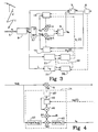
- a level detector 31 can be introduced, see fig. 3.
- the level detector 31 reads the level L of the reference signal/common mode signal S c .
- the level detector 31 indicates that.updating shall take place to an adaptation controller 32, which also receives the estimated frequency from the frequency estimator 21.
- the adaptation controller 32 indicates this to the frequency address generating unit 22, which then generates new addresses a I(f) , a Q(f) .
- updating takes place when the level has been above the threshold value for a certain period of time.
- This can also be generalised to a common controlling if updating is to take place or not. For example, there can be different interference at different frequencies and at different levels at the same time, so that particular consideration must be taken. If a receiver 9 is used it is also possible that the receiver 9 signals to the adaptation controller 32 when silent periods occur if it is desirable to consider this.
- fig. 3 also illustrates an alternative way to connect the frequency estimator 21, namely directly to the reference signal/common mode signal S c .
- the result is added in an adder 45 to a memory 46 where the address a Q(f) is chosen by the frequency address generating unit 22, and is D/A converted in a D/A converter 47, thereby obtaining a weight coefficient Q(f) which can be multiplied in the multiplier 5 to the reference signal s c .
- the multiplications can for example be implemented using XOR-gates and the multiplication with the adaptation constant ⁇ Q can for example be implemented as a shift operation.
- the invention as described above can besides being used for cancelling interference from radio amateurs, radio pirates and the like also be used in other areas where it is desired to cancel electromagnetic interference, in particular interference having a small bandwidth.
Landscapes
- Engineering & Computer Science (AREA)
- Computer Networks & Wireless Communication (AREA)
- Signal Processing (AREA)
- Noise Elimination (AREA)
Applications Claiming Priority (3)
| Application Number | Priority Date | Filing Date | Title |
|---|---|---|---|
| SE9803642A SE512979C2 (sv) | 1998-10-23 | 1998-10-23 | Anordning och förfarande för störningsdämpning av elektromagnetiska störningar |
| SE9803642 | 1998-10-23 | ||
| PCT/SE1999/001845 WO2000025434A1 (en) | 1998-10-23 | 1999-10-13 | Arrangement and method for interference cancelling |
Publications (2)
| Publication Number | Publication Date |
|---|---|
| EP1123582A1 EP1123582A1 (en) | 2001-08-16 |
| EP1123582B1 true EP1123582B1 (en) | 2007-07-11 |
Family
ID=20413067
Family Applications (1)
| Application Number | Title | Priority Date | Filing Date |
|---|---|---|---|
| EP99971166A Expired - Lifetime EP1123582B1 (en) | 1998-10-23 | 1999-10-13 | Arrangement and method for interference cancelling |
Country Status (8)
| Country | Link |
|---|---|
| US (1) | US7010277B1 (da) |
| EP (1) | EP1123582B1 (da) |
| CN (1) | CN1324518A (da) |
| AU (1) | AU767997B2 (da) |
| DE (1) | DE69936530T2 (da) |
| DK (1) | DK1123582T3 (da) |
| SE (1) | SE512979C2 (da) |
| WO (1) | WO2000025434A1 (da) |
Families Citing this family (14)
| Publication number | Priority date | Publication date | Assignee | Title |
|---|---|---|---|---|
| US6384589B1 (en) * | 2001-04-04 | 2002-05-07 | Tektronix, Inc. | Reference frequency spur cancellation in synthesized measurement receivers |
| TW569526B (en) * | 2002-12-05 | 2004-01-01 | Mediatek Inc | Adaptive filter with GSPT LMS algorithm for reducing complexity |
| US7392031B2 (en) * | 2003-06-25 | 2008-06-24 | Nxp B.V. | Method for cancelling a narrow-band interference signal |
| WO2005050869A1 (en) * | 2003-10-31 | 2005-06-02 | Telefonaktiebolaget Lm Ericsson (Publ) | Multiple access interference cancellation |
| US7046753B2 (en) * | 2004-06-29 | 2006-05-16 | Provigent Ltd. | Interference canceller with fast phase adaptation |
| EP1648093B1 (en) | 2004-10-15 | 2011-08-03 | Broadcom Corporation | Spur harmonic canceller for RF band clock |
| CN101534135B (zh) * | 2008-03-12 | 2013-06-26 | 华为技术有限公司 | 解决干扰频率的方法、设备及系统 |
| US8249540B1 (en) | 2008-08-07 | 2012-08-21 | Hypres, Inc. | Two stage radio frequency interference cancellation system and method |
| CN102082747B (zh) * | 2009-11-27 | 2014-01-08 | 西安费斯达自动化工程有限公司 | 一种tcas系统锁频滤波方法 |
| US8812571B2 (en) * | 2011-05-12 | 2014-08-19 | Telefonaktiebolaget L M Ericsson (Publ) | Spectrum agile radio |
| CN102647169B (zh) * | 2012-04-24 | 2014-10-15 | 中国科学院电工研究所 | 一种用于电缆微弱电压信号检测的降噪装置 |
| CN105119662B (zh) * | 2015-09-10 | 2017-08-01 | 湖南迈克森伟电子科技有限公司 | 无线电抗干扰设备 |
| US10014914B1 (en) * | 2017-06-13 | 2018-07-03 | Hughes Network Systems, L.L.C. | Adaptive interference canceller for multiple reference inputs |
| CN111585530B (zh) * | 2020-04-10 | 2022-05-20 | 中国科学院西安光学精密机械研究所 | 一种共模信号去除方法 |
Family Cites Families (17)
| Publication number | Priority date | Publication date | Assignee | Title |
|---|---|---|---|---|
| US4434505A (en) * | 1982-12-01 | 1984-02-28 | The United States Of America As Represented By The Secretary Of The Army | Interference cancelling system for a mobile subscriber access communications system |
| US4608569A (en) * | 1983-09-09 | 1986-08-26 | General Electric Company | Adaptive signal processor for interference cancellation |
| US4760540A (en) * | 1984-11-29 | 1988-07-26 | Rca Corporation | Adaptive interference cancelling system and method |
| GB2169477B (en) * | 1984-12-13 | 1988-08-17 | Plessey Co Plc | Improvements in or relating to communication receivers |
| US4996484A (en) * | 1988-12-29 | 1991-02-26 | Atlantic Richfield Company | Method and apparatus for cancelling powerline noise in geophysical electromagnetic exploration |
| US4952193A (en) * | 1989-03-02 | 1990-08-28 | American Nucleonics Corporation | Interference cancelling system and method |
| US4995104A (en) * | 1989-05-08 | 1991-02-19 | At&T Bell Laboratories | Interference cancelling circuit and method |
| GB2245102A (en) | 1990-06-16 | 1991-12-18 | British Aerospace | A frequency reuse phased array antenna system |
| US5047736A (en) * | 1990-09-10 | 1991-09-10 | Technology Research International, Inc. | Selective interference reduction in transmission lines |
| DE4105123A1 (de) * | 1991-02-19 | 1992-08-27 | Becker Autoradio | Schaltungsanordnung zur unterdrueckung von stoersignalen |
| US5224122A (en) * | 1992-06-29 | 1993-06-29 | Motorola, Inc. | Method and apparatus for canceling spread-spectrum noise |
| US5920539A (en) * | 1995-01-25 | 1999-07-06 | Discovision Associates | Apparatus and method for suppression of electromagnetic emissions having a groove on an external surface for passing an electrical conductor |
| GB2307150B (en) * | 1995-11-09 | 1999-10-20 | Northern Telecom Ltd | An interference reduction scheme and method |
| US5995567A (en) * | 1996-04-19 | 1999-11-30 | Texas Instruments Incorporated | Radio frequency noise canceller |
| US5825898A (en) * | 1996-06-27 | 1998-10-20 | Lamar Signal Processing Ltd. | System and method for adaptive interference cancelling |
| JPH10190495A (ja) * | 1996-12-20 | 1998-07-21 | Fujitsu Ltd | 干渉キャンセラ |
| US6178248B1 (en) * | 1997-04-14 | 2001-01-23 | Andrea Electronics Corporation | Dual-processing interference cancelling system and method |
-
1998
- 1998-10-23 SE SE9803642A patent/SE512979C2/sv not_active IP Right Cessation
-
1999
- 1999-10-13 DK DK99971166T patent/DK1123582T3/da active
- 1999-10-13 AU AU14251/00A patent/AU767997B2/en not_active Ceased
- 1999-10-13 EP EP99971166A patent/EP1123582B1/en not_active Expired - Lifetime
- 1999-10-13 US US09/807,924 patent/US7010277B1/en not_active Expired - Lifetime
- 1999-10-13 WO PCT/SE1999/001845 patent/WO2000025434A1/en not_active Ceased
- 1999-10-13 DE DE69936530T patent/DE69936530T2/de not_active Expired - Lifetime
- 1999-10-13 CN CN99812475.3A patent/CN1324518A/zh active Pending
Also Published As
| Publication number | Publication date |
|---|---|
| DE69936530T2 (de) | 2008-03-13 |
| DK1123582T3 (da) | 2007-11-05 |
| SE9803642D0 (sv) | 1998-10-23 |
| DE69936530D1 (de) | 2007-08-23 |
| CN1324518A (zh) | 2001-11-28 |
| US7010277B1 (en) | 2006-03-07 |
| EP1123582A1 (en) | 2001-08-16 |
| WO2000025434A1 (en) | 2000-05-04 |
| AU767997B2 (en) | 2003-11-27 |
| AU1425100A (en) | 2000-05-15 |
| SE9803642L (sv) | 2000-04-24 |
| SE512979C2 (sv) | 2000-06-12 |
Similar Documents
| Publication | Publication Date | Title |
|---|---|---|
| EP1123582B1 (en) | Arrangement and method for interference cancelling | |
| AU680981B2 (en) | Method for determining the location of echo in an echo cancellar | |
| EP1202469B1 (en) | Echo canceler and echo path estimating method | |
| US8023641B2 (en) | Spectral domain, non-linear echo cancellation method in a hands-free device | |
| US20020184013A1 (en) | Method of masking noise modulation and disturbing noise in voice communication | |
| JP3679245B2 (ja) | エコー消去システム及び方法、並びに移動通信装置 | |
| US6683913B1 (en) | Narrowband noise canceller | |
| US6466666B1 (en) | Method and apparatus for echo estimation and suppression | |
| US5825753A (en) | Echo canceler gain tracker for cellular modems | |
| EP0116968B1 (en) | Adaptive echo canceller | |
| JP4429533B2 (ja) | 周波数変換器 | |
| US6275087B1 (en) | Adaptive cancellation of time variant DC offset | |
| US6181791B1 (en) | Apparatus and method for reducing local interference in subscriber loop communication system | |
| US6256384B1 (en) | Method and apparatus for cancelling echo originating from a mobile terminal | |
| US4669115A (en) | Hybrid circuit and method | |
| US6920471B2 (en) | Compensation scheme for reducing delay in a digital impedance matching circuit to improve return loss | |
| JP2949989B2 (ja) | エコー消去装置 | |
| KR100456759B1 (ko) | 무선주파수노이즈소거기 | |
| KR100431965B1 (ko) | 시변 적응알고리즘이 적용된 음향반향 제거장치 및 그 방법 | |
| JP3419130B2 (ja) | エコーキャンセラ装置 | |
| KR20080058870A (ko) | Ics중계기의 간섭제거장치 | |
| JP3043767B2 (ja) | エコーキャンセル方式及びエコーキャンセラ | |
| JPH11150491A (ja) | 回線レベル制御装置及びこれを有するエコーキャンセル装置 | |
| JPH07123237B2 (ja) | デ−タ伝送用エコ−キヤンセル装置 | |
| JPH11344999A (ja) | ノイズキャンセラ |
Legal Events
| Date | Code | Title | Description |
|---|---|---|---|
| PUAI | Public reference made under article 153(3) epc to a published international application that has entered the european phase |
Free format text: ORIGINAL CODE: 0009012 |
|
| 17P | Request for examination filed |
Effective date: 20010414 |
|
| AK | Designated contracting states |
Kind code of ref document: A1 Designated state(s): AT BE CH CY DE DK ES FI FR GB GR IE IT LI LU MC NL PT SE |
|
| RAP1 | Party data changed (applicant data changed or rights of an application transferred) |
Owner name: TELEFONAKTIEBOLAGET LM ERICSSON (PUBL) |
|
| RBV | Designated contracting states (corrected) |
Designated state(s): DE DK FR GB |
|
| GRAP | Despatch of communication of intention to grant a patent |
Free format text: ORIGINAL CODE: EPIDOSNIGR1 |
|
| GRAS | Grant fee paid |
Free format text: ORIGINAL CODE: EPIDOSNIGR3 |
|
| GRAA | (expected) grant |
Free format text: ORIGINAL CODE: 0009210 |
|
| AK | Designated contracting states |
Kind code of ref document: B1 Designated state(s): DE DK FR GB |
|
| REG | Reference to a national code |
Ref country code: GB Ref legal event code: FG4D |
|
| REF | Corresponds to: |
Ref document number: 69936530 Country of ref document: DE Date of ref document: 20070823 Kind code of ref document: P |
|
| REG | Reference to a national code |
Ref country code: DK Ref legal event code: T3 |
|
| ET | Fr: translation filed | ||
| PLBE | No opposition filed within time limit |
Free format text: ORIGINAL CODE: 0009261 |
|
| STAA | Information on the status of an ep patent application or granted ep patent |
Free format text: STATUS: NO OPPOSITION FILED WITHIN TIME LIMIT |
|
| 26N | No opposition filed |
Effective date: 20080414 |
|
| PGFP | Annual fee paid to national office [announced via postgrant information from national office to epo] |
Ref country code: DK Payment date: 20131025 Year of fee payment: 15 |
|
| PGFP | Annual fee paid to national office [announced via postgrant information from national office to epo] |
Ref country code: GB Payment date: 20131028 Year of fee payment: 15 Ref country code: FR Payment date: 20131017 Year of fee payment: 15 Ref country code: DE Payment date: 20131029 Year of fee payment: 15 |
|
| REG | Reference to a national code |
Ref country code: DE Ref legal event code: R119 Ref document number: 69936530 Country of ref document: DE |
|
| REG | Reference to a national code |
Ref country code: DK Ref legal event code: EBP Effective date: 20141031 |
|
| GBPC | Gb: european patent ceased through non-payment of renewal fee |
Effective date: 20141013 |
|
| PG25 | Lapsed in a contracting state [announced via postgrant information from national office to epo] |
Ref country code: GB Free format text: LAPSE BECAUSE OF NON-PAYMENT OF DUE FEES Effective date: 20141013 Ref country code: DE Free format text: LAPSE BECAUSE OF NON-PAYMENT OF DUE FEES Effective date: 20150501 |
|
| REG | Reference to a national code |
Ref country code: FR Ref legal event code: ST Effective date: 20150630 |
|
| PG25 | Lapsed in a contracting state [announced via postgrant information from national office to epo] |
Ref country code: FR Free format text: LAPSE BECAUSE OF NON-PAYMENT OF DUE FEES Effective date: 20141031 |
|
| PG25 | Lapsed in a contracting state [announced via postgrant information from national office to epo] |
Ref country code: DK Free format text: LAPSE BECAUSE OF NON-PAYMENT OF DUE FEES Effective date: 20141031 |