EP1123188B1 - Rückstromsperre für die plastifizier- und einspritzeinheit in spritzgiessmaschinen - Google Patents
Rückstromsperre für die plastifizier- und einspritzeinheit in spritzgiessmaschinen Download PDFInfo
- Publication number
- EP1123188B1 EP1123188B1 EP99955724A EP99955724A EP1123188B1 EP 1123188 B1 EP1123188 B1 EP 1123188B1 EP 99955724 A EP99955724 A EP 99955724A EP 99955724 A EP99955724 A EP 99955724A EP 1123188 B1 EP1123188 B1 EP 1123188B1
- Authority
- EP
- European Patent Office
- Prior art keywords
- return valve
- wings
- pins
- blocking sleeve
- valve according
- Prior art date
- Legal status (The legal status is an assumption and is not a legal conclusion. Google has not performed a legal analysis and makes no representation as to the accuracy of the status listed.)
- Expired - Lifetime
Links
- 238000001746 injection moulding Methods 0.000 title claims abstract description 8
- 238000002347 injection Methods 0.000 title claims description 5
- 239000007924 injection Substances 0.000 title claims description 5
- 239000000463 material Substances 0.000 claims abstract description 11
- 239000002184 metal Substances 0.000 claims description 3
- 150000001247 metal acetylides Chemical class 0.000 claims description 2
- 230000000903 blocking effect Effects 0.000 claims 7
- 239000000919 ceramic Substances 0.000 claims 1
- 239000012815 thermoplastic material Substances 0.000 claims 1
- 230000004888 barrier function Effects 0.000 abstract description 4
- 229920001169 thermoplastic Polymers 0.000 abstract description 3
- 239000004416 thermosoftening plastic Substances 0.000 abstract description 2
- 238000000034 method Methods 0.000 description 5
- 239000004033 plastic Substances 0.000 description 3
- 229920003023 plastic Polymers 0.000 description 3
- 229920000426 Microplastic Polymers 0.000 description 1
- 229910010293 ceramic material Inorganic materials 0.000 description 1
- 150000001875 compounds Chemical class 0.000 description 1
- 238000011161 development Methods 0.000 description 1
- 230000018109 developmental process Effects 0.000 description 1
- 238000002845 discoloration Methods 0.000 description 1
- 238000006073 displacement reaction Methods 0.000 description 1
- 238000010438 heat treatment Methods 0.000 description 1
- 239000004413 injection moulding compound Substances 0.000 description 1
- 239000002994 raw material Substances 0.000 description 1
- 230000003716 rejuvenation Effects 0.000 description 1
Images


Classifications
-
- B—PERFORMING OPERATIONS; TRANSPORTING
- B29—WORKING OF PLASTICS; WORKING OF SUBSTANCES IN A PLASTIC STATE IN GENERAL
- B29C—SHAPING OR JOINING OF PLASTICS; SHAPING OF MATERIAL IN A PLASTIC STATE, NOT OTHERWISE PROVIDED FOR; AFTER-TREATMENT OF THE SHAPED PRODUCTS, e.g. REPAIRING
- B29C45/00—Injection moulding, i.e. forcing the required volume of moulding material through a nozzle into a closed mould; Apparatus therefor
- B29C45/17—Component parts, details or accessories; Auxiliary operations
- B29C45/46—Means for plasticising or homogenising the moulding material or forcing it into the mould
- B29C45/47—Means for plasticising or homogenising the moulding material or forcing it into the mould using screws
- B29C45/50—Axially movable screw
- B29C45/52—Non-return devices
-
- B—PERFORMING OPERATIONS; TRANSPORTING
- B29—WORKING OF PLASTICS; WORKING OF SUBSTANCES IN A PLASTIC STATE IN GENERAL
- B29C—SHAPING OR JOINING OF PLASTICS; SHAPING OF MATERIAL IN A PLASTIC STATE, NOT OTHERWISE PROVIDED FOR; AFTER-TREATMENT OF THE SHAPED PRODUCTS, e.g. REPAIRING
- B29C45/00—Injection moulding, i.e. forcing the required volume of moulding material through a nozzle into a closed mould; Apparatus therefor
- B29C45/17—Component parts, details or accessories; Auxiliary operations
- B29C45/46—Means for plasticising or homogenising the moulding material or forcing it into the mould
- B29C45/47—Means for plasticising or homogenising the moulding material or forcing it into the mould using screws
- B29C45/50—Axially movable screw
- B29C45/52—Non-return devices
- B29C2045/526—Abrasion resistant means in the screw head or non-return device
Definitions
- the invention relates to a non-return valve for the plasticizing and injection screw In injection molding machines, especially for the processing of thermoplastic Plastics having an axially displaceable locking sleeve, the one between Wings and a stop ring existing tapered area of an im Screw head fixed body encloses with radial play.
- Such a non-return valve is known from DE-A-3 711 775.
- JP62 130 818 shows a plasticizing in injection molding machines with a plasticizing cylinder, in which a rotatable and axially displaceable screw is arranged on the head side, a return flow lock is provided which has an axially displaceable locking sleeve, which is present between grooves and a stop ring includes tapered region of a fixed in the screw head body with radial Spiet. At the locking sleeve facing surfaces of the base support elements are provided, which are constructed of low-wear, ceramic material.
- Non-return valve has, which defines the greatest possible reliability at ensures low wear and minimal damage to the plastic material.
- support elements are provided on the wings of the base body, wherein at least the bearing surfaces are constructed of a low-wear material.
- the locking sleeve is supported evenly on these low-wear bearing surfaces during the dosing process. Due to the constant, as three plain bearings acting bearing surfaces, the frictional force to the contact surface of the locking sleeve is calculable and constant during the dosing process. Furthermore, measures are provided during the dosing process, ie with rotating screw and relative movement between the wings of the body and the locking sleeve to influence the plastic material located here as little as possible, in particular to prevent damage to the raw material.
- the support elements are designed as pins and arranged at a right angle to the support surface of the locking sleeve.
- the pins are flared in the direction of the locking sleeve, so that they can bessichemd pressed into the wings.
- arranged at the foot of the pins force elements which press the pins resiliently against the locking sleeve.
- the head ends of the support elements project beyond the surfaces of the wings.
- the locking sleeve facing surface of the wings is arcuate.
- the pins made of hard metal or have, at least in the region of the support surface, a layer containing carbides.
- the locking sleeve can be designed so that even a little wear in Purchase is taken, especially since it is a relatively simple in the locking sleeve is a geometric part that is easily replaceable.
- the contact surface to the support elements also from built up low-wear material, so that no wear between the Body and the locking sleeve occurs.
- the entire locking sleeve be made of a wear-reducing material.
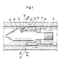
- FIG. 1 shows a part of a plasticizing cylinder 12 in which a worm 11 is arranged, at whose head a return flow lock 21 is releasably attached.
- the non-return valve 21 has a base body 22, which has a tapered region Has 23, facing the worm 11 has a stop ring 26 and the Tip towards at least three wings 24 has.
- the tapered portion 22 is enveloped by a locking sleeve 27, which in the axial direction displaced at one end on the locking sleeve facing surface 25 of the wing 24 and after displacement at the other end of the stop ring 26 is supported.
- the wings facing the support surface 28 of the locking sleeve 27 is located in the Wings 24 provided support elements 31.
- the Support member 31 configured as a pin 33, which in the direction of locking sleeve 27 is a conical has widening shape.
- the view AA is shown with a section through the Plasticizing cylinder 12 with a view of the support elements 31 of the body 22nd in the tapered portion 23.
- the wings 24 which faces the locking sleeve To see surface 25, in which the surface 32 of the support member 31 is visible.
- FIG. 3 shows a part of the main body 22 in which, in the tapered region 23 the locking sleeve 27 is arranged.
- a Support member 31 shown which has a cylindrical shape and whose Locking sleeve facing surface has a wear layer 35.
- a support element 31 is designed as a pin 33 at the foot end 34 is a force element 36 is located.
- Both support elements 31 shown in this figure protrude over the surface 25 of the Wing 24 out.
- FIG. 4 shows a detail of a wing 24 in the view BB.
- the support element 31 is configured in each case as a conical pin 33, which is pressed into the wing 24 on the head side.
- the conical hard metal pin used here is thus biased fixed in the receiving bore and whiffing of the bolt edge zones by the embedding in the receiving bore.
- the head end of the pin 33 inserted here protrudes by the dimension a beyond the surface 25 of the wing 24 addition.
- the surface 25 of the wing 24 is rounded and with a radius r. The vertex of the surface 25 is tangent to the surface 32 of the pin 33.
Landscapes
- Engineering & Computer Science (AREA)
- Manufacturing & Machinery (AREA)
- Mechanical Engineering (AREA)
- Injection Moulding Of Plastics Or The Like (AREA)
- Check Valves (AREA)
Description
An den der Sperrhülse zugewandten Flächen des Grundkörpers sind Auflageelemente vorgesehen, die aus verschleißarmem, keramischem Material aufgebaut sind.
Durch die konstante, wie drei Gleitlager wirkende Auflageflächen, ist die Reibkraft zur Berührungsfläche der Sperrhülse hin berechenbar und während des Dosiervorganges konstant.
Weiterhin sind Maßnahmen vorgesehen, während des Dosiervorganges, also bei rotierender Schnecke und relativer Bewegung zwischen den Flügeln des Grundkörpers und der Sperrhülse das hier befindliche Kunststoffmaterial so wenig wie möglich zu beeinflussen, insbesondere eine Schädigung des Rohstoffes zu verhindern.
Die Auflageelemente sind als Stifte ausgebildet und unter einem rechten Winkel zur Abstützfläche der Sperrhülse angeordnet. Wetterhin sind die Stifte in Richtung der Sperrhülse konisch erweitert, so daß sie selbstsichemd in die Flügel eingepreßt werden können.
Um ein gleichmäßiges, verschleißarmes Anliegen der Abstützfläche der Sperrhülse an den Stiften zu ermöglichen, sind, insbesondere bei dem Einsatz von mehr als drei Flügeln, am Fußende der Stifte Kraftelemente angeordnet, die die Stifte federnd gegen die Sperrhülse drücken.
In zweckmäßiger Weise überragen die Kopfenden der Auflageelemente die Flächen der Flügel. In der anderen Ausgestaltung ist die der Sperrhülse zugewandte Fläche der Flügel bogenförmig ausgebildet. In beiden Fällen wird eine Gleitbewegung zwischen der Flügelfläche und der Sperrhülsefläche vermieden, so daß es nicht zu Schlieren oder zu Verfärbungen am Formteil kommen kann.
In einer vorteilhaften Ausgestaltung sind die Stifte aus Hartmetall oder weisen, zumindestens im Bereich der Auflagefläche, eine Schicht auf, die Karbide enthält.
- Figur 1
- ein Detail des Plastifizierzylinders mit dem Kopf der Schnecke,
- Figur 2
- eine Schnittansicht in Richtung AA nach Fig. 1,
- Figur 3
- einen Grundkörper mit Sperrhülse,
- Figur 4
- den Schnitt eines Flügels, Ansicht BB.
Das Kopfende des hier eingesetzten Stiftes 33 ragt um das Maß a über die Fläche 25 des Flügels 24 hinaus.
Im rechten Teil ist in der Figur 4b die Fläche 25 des Flügels 24 abgerundet und zwar mit einem Radius r. Der Scheitelpunkt der Fläche 25 tangiert die Fläche 32 des Stiftes 33.
- 11
- Schnecke
- 12
- Plastifizierzylinder
- 21
- Rückstromsperre
- 22
- Grundkörper
- 23
- Verjüngter Bereich (22)
- 24
- Flügel (22)
- 25
- Der Sperrhülse (27) zugewandte Fläche (24)
- 26
- Anschlagring
- 27
- Sperrhülse
- 28
- Den Flügeln (24) zugewandte Abstützfläche (27)
- 31
- Auflageelement
- 32
- Fläche (31)
- 33
- Stift
- 34
- Fußende Stift (33)
- 35
- Verschleißschicht
- 36
- Kraftelement
- h
- Maß des Überragens (32 zu 25)
- b
- Dicke des Flügels
- d
- Durchmesser (31)
- r
- Radius (24)
Claims (7)
- Rückströmsperre für die Plastifizier- und Einspritzschnecke in Spritzgießmaschinen, insbesondere für die Verarbeitung von thermoplastischen Kunststoffen, die eine axial verschiebbare Sperrhülse aufweist, die einen zwischen Flügeln und einem Anschlagring vorhandenen verjüngten Bereich eines im Schneckenkopf fixierten Grundkörpers mit radialem Spiel umschließt,
dadurch gekennzeichnet,daß der Grundkörper (22) mindestens drei Flügel (24) besitzt,daß an den der Sperrhülse (27) zugewandten Flächen (25) der Flügel (24) Auflageelemente (31) vorgesehen sind,daß die Auflageelemente (31) als Stifte (33) ausgebildet sind,daß die Stifte (33) unter einem rechten Winkel zur Abstützfläche (28) der Sperrhülse (27) angeordnet sind,daß mindestens die Auflageflächen (32) der Auflageelemente (31) aus einem verschleißarmen Werkstoff aufgebaut sind,daß die Stifte (33) in Richtung Sperrhülse (27) sich konisch erweitern, unddaß am Fußende (34) der Stifte (33) Kraftelemente (36) angeordnet sind, die ein gleichmäßiges Anpressen der Flächen (32) der Stifte (33) gegen die Abstützfläche (28) der Sperrhülse (27) sichern. - Rückströmsperre nach Anspruch 1,
dadurch gekennzeichnet, daß das Kopfende der Auflageelemente (31) die Flächen (25) der Flügel (24) überragt. - Rückströmsperre nach Anspruch 1,
dadurch gekennzeichnet, daß die der Sperrhülse (27) zugewandte Fläche (25) der Flügel (24) bogenförmig ausgestaltet ist und
daß im Scheitel der höchsten Erhebung der Fläche (25) das Auflageelement (31) angeordnet ist. - Rückströmsperre nach Anspruch 3,
dadurch gekennzeichnet, daß die bogenförmige Ausgestaltung der Fläche (25) eine einfache kreisförmige Abrundung ist mit einem Radius (r) von r > ½ * b mit b = Dicke des Flügels (24) in seinem Kopfbereich. - Rückströmsperre nach Anspruch 1,
dadurch gekennzeichnet, daß zumindestens der mit den Auflageflächen (32) der Auflageelemente (31) korrespondierende Bereich der Sperrhülse (27) aus einem verschleißarmen Werkstoff aufgebaut ist. - Rückströmsperre nach Anspruch 1,
dadurch gekennzeichnet, daß die Stifte aus Hartmetall oder Keramik sind. - Rückströmsperre nach Anspruch 1 oder 5,
dadurch gekennzeichnet, daß die Flächen (32) der Auflageelemente (31) eine Karbide oder Boride aufweisende Verschleißschicht (35) besitzen.
Applications Claiming Priority (3)
| Application Number | Priority Date | Filing Date | Title |
|---|---|---|---|
| DE19849472A DE19849472C2 (de) | 1998-10-21 | 1998-10-21 | Rückströmsperre für die Plastifizier- und Einspritzschnecke in Spritzgießmaschinen |
| DE19849472 | 1998-10-21 | ||
| PCT/DE1999/002971 WO2000023248A1 (de) | 1998-10-21 | 1999-09-14 | Plastifiziereinheit in spritzgiessmaschinen mit rückstromsperre |
Publications (2)
| Publication Number | Publication Date |
|---|---|
| EP1123188A1 EP1123188A1 (de) | 2001-08-16 |
| EP1123188B1 true EP1123188B1 (de) | 2003-10-29 |
Family
ID=7885780
Family Applications (1)
| Application Number | Title | Priority Date | Filing Date |
|---|---|---|---|
| EP99955724A Expired - Lifetime EP1123188B1 (de) | 1998-10-21 | 1999-09-14 | Rückstromsperre für die plastifizier- und einspritzeinheit in spritzgiessmaschinen |
Country Status (6)
| Country | Link |
|---|---|
| US (1) | US6554603B1 (de) |
| EP (1) | EP1123188B1 (de) |
| AT (1) | ATE252973T1 (de) |
| AU (1) | AU1260300A (de) |
| DE (2) | DE19849472C2 (de) |
| WO (1) | WO2000023248A1 (de) |
Families Citing this family (12)
| Publication number | Priority date | Publication date | Assignee | Title |
|---|---|---|---|---|
| DE10103863C1 (de) * | 2001-01-30 | 2002-08-08 | Karl Hehl | Verfahren zur Herstellung eines Führungselements einer Rückstromsperre sowie entsprechendes Führungselement |
| DE10210464B4 (de) * | 2002-03-09 | 2007-07-26 | Demag Ergotech Gmbh | Rückströmsperre |
| DE10217758B4 (de) * | 2002-04-20 | 2005-06-16 | Krauss-Maffei Kunststofftechnik Gmbh | Rückstromsperre für Spritzgießmaschine |
| DE102004051105A1 (de) * | 2004-10-19 | 2006-04-27 | Billion S.A. | Plastifizier- und Einspritzvorrichtung |
| JP2006168218A (ja) * | 2004-12-16 | 2006-06-29 | Meiki Co Ltd | 射出装置 |
| CL2008001727A1 (es) * | 2007-06-12 | 2010-02-05 | Gillette Co | Maquina de afeitar que comprende un mango con un extremo proximal y otro distal, un cuello de adaptador unido de manera pivotante al extremo proximal del mango, una bomba unida a un canal alimentador, una horquilla de conexion a un cartucho y un cartucho para maquina de afeitar. |
| US7527493B1 (en) * | 2007-11-01 | 2009-05-05 | Md Plastics Incorporated | Precise control non-return valve |
| CA2741624A1 (en) * | 2008-12-10 | 2010-06-17 | Husky Injection Molding Systems Ltd. | Improved check valve |
| DE102017108895A1 (de) | 2017-04-26 | 2018-10-31 | Schaeffler Technologies AG & Co. KG | Plastifiziereinheit für eine Spritzgießmaschine |
| AT522179B1 (de) | 2019-04-25 | 2020-09-15 | Engel Austria Gmbh | Plastifizierschnecke für eine Formgebungsmaschine |
| CN110001015B (zh) * | 2019-05-20 | 2021-04-30 | 台州市永硕汽车部件有限公司 | 一种注塑机的注塑螺杆 |
| DE102023111743B3 (de) | 2023-05-05 | 2024-09-12 | Arburg Gmbh + Co Kg | Verfahren zur Herstellung eines Führungselements einer Rückstromsperre sowie ein entsprechendes Führungselement |
Family Cites Families (13)
| Publication number | Priority date | Publication date | Assignee | Title |
|---|---|---|---|---|
| DE7919878U1 (de) * | 1979-07-11 | 1979-12-20 | Koninklijke Machinefabriek Stork B.V., Hengelo (Niederlande) | Spritzgussmaschine mit spritzeinheit |
| EP0027616B1 (de) * | 1979-10-19 | 1983-06-22 | Mannesmann Demag Kunststofftechnik Zweigniederlassung Der Mannesmann Demag Aktiengesellschaft | Rückströmsperre am Schneckenkopf von Schneckenspritzgiessmaschinen |
| JPS61246031A (ja) * | 1985-04-25 | 1986-11-01 | Japan Steel Works Ltd:The | 射出成形機の逆流防止装置 |
| US4701293A (en) * | 1985-09-24 | 1987-10-20 | Grumman Aerospace Corporation | Molding process and apparatus utilizing memory metal alloy springs |
| JPS62130818A (ja) * | 1985-11-30 | 1987-06-13 | Meiki Co Ltd | 射出成形機 |
| CH670065A5 (de) * | 1986-05-13 | 1989-05-12 | Netstal Ag Maschf Giesserei | |
| DE3717735C1 (en) * | 1987-05-26 | 1988-02-18 | Krauss Maffei Ag | Non-return valve for a plastication screw |
| US5167971A (en) * | 1991-07-29 | 1992-12-01 | Gill Joseph R | Check valve assembly for injection molding apparatus |
| JP2894880B2 (ja) * | 1991-09-13 | 1999-05-24 | 株式会社ペトカ | ピッチ系炭素繊維紡糸用口金 |
| US5441400A (en) * | 1994-04-07 | 1995-08-15 | Zeiger; Donald J. | Spring biased check valve for an injection molding machine |
| FR2718800B1 (fr) * | 1994-04-13 | 1996-07-12 | Alain Georges Rene Viron | Clapet à goupille flottante et autocentrante à deux points d'appuis sur méplats usinés ou forgés suivant un angle donné. |
| JP2857845B2 (ja) * | 1995-02-20 | 1999-02-17 | 日精樹脂工業株式会社 | 射出成形機のスクリュヘッド装置 |
| DE29701495U1 (de) * | 1997-01-30 | 1997-03-27 | Battenfeld Gmbh, 58540 Meinerzhagen | Rückstromsperre |
-
1998
- 1998-10-21 DE DE19849472A patent/DE19849472C2/de not_active Expired - Lifetime
-
1999
- 1999-09-14 US US09/830,093 patent/US6554603B1/en not_active Expired - Lifetime
- 1999-09-14 AT AT99955724T patent/ATE252973T1/de active
- 1999-09-14 WO PCT/DE1999/002971 patent/WO2000023248A1/de not_active Ceased
- 1999-09-14 DE DE59907565T patent/DE59907565D1/de not_active Expired - Lifetime
- 1999-09-14 AU AU12603/00A patent/AU1260300A/en not_active Abandoned
- 1999-09-14 EP EP99955724A patent/EP1123188B1/de not_active Expired - Lifetime
Also Published As
| Publication number | Publication date |
|---|---|
| DE19849472C2 (de) | 2002-11-28 |
| ATE252973T1 (de) | 2003-11-15 |
| DE19849472A1 (de) | 2000-04-27 |
| AU1260300A (en) | 2000-05-08 |
| DE59907565D1 (de) | 2003-12-04 |
| WO2000023248A1 (de) | 2000-04-27 |
| US6554603B1 (en) | 2003-04-29 |
| EP1123188A1 (de) | 2001-08-16 |
Similar Documents
| Publication | Publication Date | Title |
|---|---|---|
| DE19849472C2 (de) | Rückströmsperre für die Plastifizier- und Einspritzschnecke in Spritzgießmaschinen | |
| DE68902084T2 (de) | Mischvorrichtung mit verteilungsmischwirkung fuer eine schneckenpresse, eine spritzgiessmaschine und dergleichen. | |
| EP0113853B1 (de) | Rückströmsperre | |
| EP2364813B1 (de) | Honwerkzeug | |
| DE4141891A1 (de) | Zahnbuerste | |
| DE4136537C1 (de) | ||
| DE2006389C3 (de) | Rückflußsperre für Spritzgieß-Schneckenkolbenmaschinen zum Verarbeiten von plastischen Massen mit einer umlaufenden und axial verschiebbaren Schnecke | |
| EP0027616B1 (de) | Rückströmsperre am Schneckenkopf von Schneckenspritzgiessmaschinen | |
| DE1928176A1 (de) | Walzenbrikettpresse zum Heissverpressen von Kohle,Erzen und aehnlichen Stoffen | |
| DE8616697U1 (de) | Reifenvulkanisierform | |
| DE29701495U1 (de) | Rückstromsperre | |
| EP1342547A1 (de) | Rückströmsperre | |
| DE20213902U1 (de) | Klinkenzug | |
| DE3142756C2 (de) | Rückströmsperre für eine Schneckenspritzgießmaschine | |
| DE3711775A1 (de) | Plastifizier- und spritzeinheit einer kunststoff- spritzgiessmaschine mit rueckstroemsperre | |
| DE2432003B2 (de) | Dichtring | |
| DE19701025C2 (de) | Markierungseinsatz, insbesondere für Kunststoff-Spritzgießwerkzeuge | |
| DE69909706T2 (de) | Drosselmittel für extruder am transfermischertyp | |
| DE1779711A1 (de) | Spritzgiessmaschine | |
| EP3656581A1 (de) | Gleitschutzstift | |
| DE3717735C1 (en) | Non-return valve for a plastication screw | |
| DE10241262B4 (de) | Schneckenkopf mit Rückstromsperre | |
| EP1060863B1 (de) | Vorrichtung zum Spritzgiessen von Formlingen | |
| EP1226920B1 (de) | Verfahren zur Herstellung einer Sperrhülse für eine Rückstromsperre einer Kunststoff-Spritzgiessmaschine | |
| DE10217758A1 (de) | Rückstromsperre für Spritzgießmaschine |
Legal Events
| Date | Code | Title | Description |
|---|---|---|---|
| PUAI | Public reference made under article 153(3) epc to a published international application that has entered the european phase |
Free format text: ORIGINAL CODE: 0009012 |
|
| 17P | Request for examination filed |
Effective date: 20010427 |
|
| AK | Designated contracting states |
Kind code of ref document: A1 Designated state(s): AT BE CH CY DE DK ES FI FR GB GR IE IT LI LU MC NL PT SE |
|
| RIN1 | Information on inventor provided before grant (corrected) |
Inventor name: STRENG DIETER Inventor name: SEIDEL, JOERG Inventor name: SCHIMMEL, DIETER Inventor name: SCHREINER, HELMUT |
|
| 17Q | First examination report despatched |
Effective date: 20020124 |
|
| RTI1 | Title (correction) |
Free format text: NONRETURN VALVE FOR PLASTIFYING AND INJECTION UNIT IN INJECTION-MOULDING MACHINES |
|
| GRAH | Despatch of communication of intention to grant a patent |
Free format text: ORIGINAL CODE: EPIDOS IGRA |
|
| RTI1 | Title (correction) |
Free format text: NONRETURN VALVE FOR PLASTIFYING AND INJECTION UNIT IN INJECTION-MOULDING MACHINES |
|
| RIN1 | Information on inventor provided before grant (corrected) |
Inventor name: STRENG DIETER Inventor name: SEIDEL, JOERG Inventor name: SCHIMMEL, DIETER Inventor name: SCHREINER, HELMUT |
|
| RIN1 | Information on inventor provided before grant (corrected) |
Inventor name: SEIDEL, JOERG Inventor name: SCHIMMEL, DIETER Inventor name: SCHREINER, HELMUT |
|
| GRAH | Despatch of communication of intention to grant a patent |
Free format text: ORIGINAL CODE: EPIDOS IGRA |
|
| GRAA | (expected) grant |
Free format text: ORIGINAL CODE: 0009210 |
|
| AK | Designated contracting states |
Kind code of ref document: B1 Designated state(s): AT BE CH CY DE DK ES FI FR GB GR IE IT LI LU MC NL PT SE |
|
| PG25 | Lapsed in a contracting state [announced via postgrant information from national office to epo] |
Ref country code: NL Free format text: LAPSE BECAUSE OF FAILURE TO SUBMIT A TRANSLATION OF THE DESCRIPTION OR TO PAY THE FEE WITHIN THE PRESCRIBED TIME-LIMIT Effective date: 20031029 Ref country code: IE Free format text: LAPSE BECAUSE OF FAILURE TO SUBMIT A TRANSLATION OF THE DESCRIPTION OR TO PAY THE FEE WITHIN THE PRESCRIBED TIME-LIMIT Effective date: 20031029 Ref country code: GB Free format text: LAPSE BECAUSE OF FAILURE TO SUBMIT A TRANSLATION OF THE DESCRIPTION OR TO PAY THE FEE WITHIN THE PRESCRIBED TIME-LIMIT Effective date: 20031029 Ref country code: FI Free format text: LAPSE BECAUSE OF FAILURE TO SUBMIT A TRANSLATION OF THE DESCRIPTION OR TO PAY THE FEE WITHIN THE PRESCRIBED TIME-LIMIT Effective date: 20031029 Ref country code: ES Free format text: LAPSE BECAUSE OF FAILURE TO SUBMIT A TRANSLATION OF THE DESCRIPTION OR TO PAY THE FEE WITHIN THE PRESCRIBED TIME-LIMIT Effective date: 20031029 Ref country code: CY Free format text: LAPSE BECAUSE OF FAILURE TO SUBMIT A TRANSLATION OF THE DESCRIPTION OR TO PAY THE FEE WITHIN THE PRESCRIBED TIME-LIMIT Effective date: 20031029 |
|
| REG | Reference to a national code |
Ref country code: GB Ref legal event code: FG4D Free format text: NOT ENGLISH |
|
| REG | Reference to a national code |
Ref country code: CH Ref legal event code: EP |
|
| REG | Reference to a national code |
Ref country code: CH Ref legal event code: NV Representative=s name: E. BLUM & CO. PATENTANWAELTE |
|
| REG | Reference to a national code |
Ref country code: IE Ref legal event code: FG4D Free format text: GERMAN |
|
| REF | Corresponds to: |
Ref document number: 59907565 Country of ref document: DE Date of ref document: 20031204 Kind code of ref document: P |
|
| PG25 | Lapsed in a contracting state [announced via postgrant information from national office to epo] |
Ref country code: SE Free format text: LAPSE BECAUSE OF FAILURE TO SUBMIT A TRANSLATION OF THE DESCRIPTION OR TO PAY THE FEE WITHIN THE PRESCRIBED TIME-LIMIT Effective date: 20040129 Ref country code: GR Free format text: LAPSE BECAUSE OF FAILURE TO SUBMIT A TRANSLATION OF THE DESCRIPTION OR TO PAY THE FEE WITHIN THE PRESCRIBED TIME-LIMIT Effective date: 20040129 Ref country code: DK Free format text: LAPSE BECAUSE OF FAILURE TO SUBMIT A TRANSLATION OF THE DESCRIPTION OR TO PAY THE FEE WITHIN THE PRESCRIBED TIME-LIMIT Effective date: 20040129 |
|
| NLV1 | Nl: lapsed or annulled due to failure to fulfill the requirements of art. 29p and 29m of the patents act | ||
| GBV | Gb: ep patent (uk) treated as always having been void in accordance with gb section 77(7)/1977 [no translation filed] |
Effective date: 20031029 |
|
| ET | Fr: translation filed | ||
| PG25 | Lapsed in a contracting state [announced via postgrant information from national office to epo] |
Ref country code: DE Free format text: LAPSE BECAUSE OF THE APPLICANT RENOUNCES Effective date: 20040601 |
|
| REG | Reference to a national code |
Ref country code: IE Ref legal event code: FD4D |
|
| PLBE | No opposition filed within time limit |
Free format text: ORIGINAL CODE: 0009261 |
|
| STAA | Information on the status of an ep patent application or granted ep patent |
Free format text: STATUS: NO OPPOSITION FILED WITHIN TIME LIMIT |
|
| PG25 | Lapsed in a contracting state [announced via postgrant information from national office to epo] |
Ref country code: LU Free format text: LAPSE BECAUSE OF NON-PAYMENT OF DUE FEES Effective date: 20040914 |
|
| PG25 | Lapsed in a contracting state [announced via postgrant information from national office to epo] |
Ref country code: MC Free format text: LAPSE BECAUSE OF NON-PAYMENT OF DUE FEES Effective date: 20040930 Ref country code: BE Free format text: LAPSE BECAUSE OF NON-PAYMENT OF DUE FEES Effective date: 20040930 |
|
| 26N | No opposition filed |
Effective date: 20040730 |
|
| BERE | Be: lapsed |
Owner name: *DEMAG ERGOTECH G.M.B.H. Effective date: 20040930 |
|
| REG | Reference to a national code |
Ref country code: CH Ref legal event code: PFA Owner name: DEMAG ERGOTECH GMBH Free format text: DEMAG ERGOTECH GMBH#ALTDORFER STRASSE 15#90571 SCHWAIG (DE) -TRANSFER TO- DEMAG ERGOTECH GMBH#ALTDORFER STRASSE 15#90571 SCHWAIG (DE) |
|
| BERE | Be: lapsed |
Owner name: *DEMAG ERGOTECH G.M.B.H. Effective date: 20040930 |
|
| PG25 | Lapsed in a contracting state [announced via postgrant information from national office to epo] |
Ref country code: PT Free format text: LAPSE BECAUSE OF NON-PAYMENT OF DUE FEES Effective date: 20040329 |
|
| REG | Reference to a national code |
Ref country code: CH Ref legal event code: PFA Owner name: SUMITOMO (SHI) DEMAG PLASTICS MACHINERY GMBH Free format text: DEMAG ERGOTECH GMBH#ALTDORFER STRASSE 15#90571 SCHWAIG (DE) -TRANSFER TO- SUMITOMO (SHI) DEMAG PLASTICS MACHINERY GMBH#ALTDORFER STRASSE 15#90571 SCHWAIG (DE) |
|
| REG | Reference to a national code |
Ref country code: FR Ref legal event code: TP Ref country code: FR Ref legal event code: CD |
|
| REG | Reference to a national code |
Ref country code: FR Ref legal event code: PLFP Year of fee payment: 17 |
|
| REG | Reference to a national code |
Ref country code: FR Ref legal event code: PLFP Year of fee payment: 18 |
|
| REG | Reference to a national code |
Ref country code: FR Ref legal event code: PLFP Year of fee payment: 19 |
|
| PGFP | Annual fee paid to national office [announced via postgrant information from national office to epo] |
Ref country code: CH Payment date: 20170808 Year of fee payment: 19 Ref country code: IT Payment date: 20170926 Year of fee payment: 19 Ref country code: FR Payment date: 20170925 Year of fee payment: 19 |
|
| PGFP | Annual fee paid to national office [announced via postgrant information from national office to epo] |
Ref country code: AT Payment date: 20170811 Year of fee payment: 19 |
|
| REG | Reference to a national code |
Ref country code: CH Ref legal event code: PL |
|
| REG | Reference to a national code |
Ref country code: AT Ref legal event code: MM01 Ref document number: 252973 Country of ref document: AT Kind code of ref document: T Effective date: 20180914 |
|
| PG25 | Lapsed in a contracting state [announced via postgrant information from national office to epo] |
Ref country code: IT Free format text: LAPSE BECAUSE OF NON-PAYMENT OF DUE FEES Effective date: 20180914 |
|
| PG25 | Lapsed in a contracting state [announced via postgrant information from national office to epo] |
Ref country code: FR Free format text: LAPSE BECAUSE OF NON-PAYMENT OF DUE FEES Effective date: 20180930 Ref country code: LI Free format text: LAPSE BECAUSE OF NON-PAYMENT OF DUE FEES Effective date: 20180930 Ref country code: CH Free format text: LAPSE BECAUSE OF NON-PAYMENT OF DUE FEES Effective date: 20180930 |
|
| PG25 | Lapsed in a contracting state [announced via postgrant information from national office to epo] |
Ref country code: AT Free format text: LAPSE BECAUSE OF NON-PAYMENT OF DUE FEES Effective date: 20180914 |