EP1123069B1 - Spannungsregulierender fusionskäfig für wirbelsäulenfusionschirurgie - Google Patents
Spannungsregulierender fusionskäfig für wirbelsäulenfusionschirurgie Download PDFInfo
- Publication number
- EP1123069B1 EP1123069B1 EP98965636A EP98965636A EP1123069B1 EP 1123069 B1 EP1123069 B1 EP 1123069B1 EP 98965636 A EP98965636 A EP 98965636A EP 98965636 A EP98965636 A EP 98965636A EP 1123069 B1 EP1123069 B1 EP 1123069B1
- Authority
- EP
- European Patent Office
- Prior art keywords
- slots
- fusion cage
- intervertebral fusion
- cage according
- cage
- Prior art date
- Legal status (The legal status is an assumption and is not a legal conclusion. Google has not performed a legal analysis and makes no representation as to the accuracy of the status listed.)
- Expired - Lifetime
Links
Images


Classifications
-
- A—HUMAN NECESSITIES
- A61—MEDICAL OR VETERINARY SCIENCE; HYGIENE
- A61F—FILTERS IMPLANTABLE INTO BLOOD VESSELS; PROSTHESES; DEVICES PROVIDING PATENCY TO, OR PREVENTING COLLAPSING OF, TUBULAR STRUCTURES OF THE BODY, e.g. STENTS; ORTHOPAEDIC, NURSING OR CONTRACEPTIVE DEVICES; FOMENTATION; TREATMENT OR PROTECTION OF EYES OR EARS; BANDAGES, DRESSINGS OR ABSORBENT PADS; FIRST-AID KITS
- A61F2/00—Filters implantable into blood vessels; Prostheses, i.e. artificial substitutes or replacements for parts of the body; Appliances for connecting them with the body; Devices providing patency to, or preventing collapsing of, tubular structures of the body, e.g. stents
- A61F2/02—Prostheses implantable into the body
- A61F2/30—Joints
- A61F2/44—Joints for the spine, e.g. vertebrae, spinal discs
- A61F2/442—Intervertebral or spinal discs, e.g. resilient
-
- A—HUMAN NECESSITIES
- A61—MEDICAL OR VETERINARY SCIENCE; HYGIENE
- A61F—FILTERS IMPLANTABLE INTO BLOOD VESSELS; PROSTHESES; DEVICES PROVIDING PATENCY TO, OR PREVENTING COLLAPSING OF, TUBULAR STRUCTURES OF THE BODY, e.g. STENTS; ORTHOPAEDIC, NURSING OR CONTRACEPTIVE DEVICES; FOMENTATION; TREATMENT OR PROTECTION OF EYES OR EARS; BANDAGES, DRESSINGS OR ABSORBENT PADS; FIRST-AID KITS
- A61F2/00—Filters implantable into blood vessels; Prostheses, i.e. artificial substitutes or replacements for parts of the body; Appliances for connecting them with the body; Devices providing patency to, or preventing collapsing of, tubular structures of the body, e.g. stents
- A61F2/02—Prostheses implantable into the body
- A61F2/30—Joints
- A61F2/44—Joints for the spine, e.g. vertebrae, spinal discs
- A61F2/4455—Joints for the spine, e.g. vertebrae, spinal discs for the fusion of spinal bodies, e.g. intervertebral fusion of adjacent spinal bodies, e.g. fusion cages
-
- A—HUMAN NECESSITIES
- A61—MEDICAL OR VETERINARY SCIENCE; HYGIENE
- A61F—FILTERS IMPLANTABLE INTO BLOOD VESSELS; PROSTHESES; DEVICES PROVIDING PATENCY TO, OR PREVENTING COLLAPSING OF, TUBULAR STRUCTURES OF THE BODY, e.g. STENTS; ORTHOPAEDIC, NURSING OR CONTRACEPTIVE DEVICES; FOMENTATION; TREATMENT OR PROTECTION OF EYES OR EARS; BANDAGES, DRESSINGS OR ABSORBENT PADS; FIRST-AID KITS
- A61F2/00—Filters implantable into blood vessels; Prostheses, i.e. artificial substitutes or replacements for parts of the body; Appliances for connecting them with the body; Devices providing patency to, or preventing collapsing of, tubular structures of the body, e.g. stents
- A61F2/02—Prostheses implantable into the body
- A61F2/28—Bones
- A61F2002/2835—Bone graft implants for filling a bony defect or an endoprosthesis cavity, e.g. by synthetic material or biological material
-
- A—HUMAN NECESSITIES
- A61—MEDICAL OR VETERINARY SCIENCE; HYGIENE
- A61F—FILTERS IMPLANTABLE INTO BLOOD VESSELS; PROSTHESES; DEVICES PROVIDING PATENCY TO, OR PREVENTING COLLAPSING OF, TUBULAR STRUCTURES OF THE BODY, e.g. STENTS; ORTHOPAEDIC, NURSING OR CONTRACEPTIVE DEVICES; FOMENTATION; TREATMENT OR PROTECTION OF EYES OR EARS; BANDAGES, DRESSINGS OR ABSORBENT PADS; FIRST-AID KITS
- A61F2/00—Filters implantable into blood vessels; Prostheses, i.e. artificial substitutes or replacements for parts of the body; Appliances for connecting them with the body; Devices providing patency to, or preventing collapsing of, tubular structures of the body, e.g. stents
- A61F2/02—Prostheses implantable into the body
- A61F2/28—Bones
- A61F2002/286—Bone stimulation by mechanical vibrations for enhancing ossification
-
- A—HUMAN NECESSITIES
- A61—MEDICAL OR VETERINARY SCIENCE; HYGIENE
- A61F—FILTERS IMPLANTABLE INTO BLOOD VESSELS; PROSTHESES; DEVICES PROVIDING PATENCY TO, OR PREVENTING COLLAPSING OF, TUBULAR STRUCTURES OF THE BODY, e.g. STENTS; ORTHOPAEDIC, NURSING OR CONTRACEPTIVE DEVICES; FOMENTATION; TREATMENT OR PROTECTION OF EYES OR EARS; BANDAGES, DRESSINGS OR ABSORBENT PADS; FIRST-AID KITS
- A61F2/00—Filters implantable into blood vessels; Prostheses, i.e. artificial substitutes or replacements for parts of the body; Appliances for connecting them with the body; Devices providing patency to, or preventing collapsing of, tubular structures of the body, e.g. stents
- A61F2/02—Prostheses implantable into the body
- A61F2/30—Joints
- A61F2002/30001—Additional features of subject-matter classified in A61F2/28, A61F2/30 and subgroups thereof
- A61F2002/30108—Shapes
- A61F2002/30199—Three-dimensional shapes
- A61F2002/30224—Three-dimensional shapes cylindrical
- A61F2002/30235—Three-dimensional shapes cylindrical tubular, e.g. sleeves
-
- A—HUMAN NECESSITIES
- A61—MEDICAL OR VETERINARY SCIENCE; HYGIENE
- A61F—FILTERS IMPLANTABLE INTO BLOOD VESSELS; PROSTHESES; DEVICES PROVIDING PATENCY TO, OR PREVENTING COLLAPSING OF, TUBULAR STRUCTURES OF THE BODY, e.g. STENTS; ORTHOPAEDIC, NURSING OR CONTRACEPTIVE DEVICES; FOMENTATION; TREATMENT OR PROTECTION OF EYES OR EARS; BANDAGES, DRESSINGS OR ABSORBENT PADS; FIRST-AID KITS
- A61F2/00—Filters implantable into blood vessels; Prostheses, i.e. artificial substitutes or replacements for parts of the body; Appliances for connecting them with the body; Devices providing patency to, or preventing collapsing of, tubular structures of the body, e.g. stents
- A61F2/02—Prostheses implantable into the body
- A61F2/30—Joints
- A61F2002/30001—Additional features of subject-matter classified in A61F2/28, A61F2/30 and subgroups thereof
- A61F2002/30108—Shapes
- A61F2002/30199—Three-dimensional shapes
- A61F2002/3028—Three-dimensional shapes polyhedral different from parallelepipedal and pyramidal
-
- A—HUMAN NECESSITIES
- A61—MEDICAL OR VETERINARY SCIENCE; HYGIENE
- A61F—FILTERS IMPLANTABLE INTO BLOOD VESSELS; PROSTHESES; DEVICES PROVIDING PATENCY TO, OR PREVENTING COLLAPSING OF, TUBULAR STRUCTURES OF THE BODY, e.g. STENTS; ORTHOPAEDIC, NURSING OR CONTRACEPTIVE DEVICES; FOMENTATION; TREATMENT OR PROTECTION OF EYES OR EARS; BANDAGES, DRESSINGS OR ABSORBENT PADS; FIRST-AID KITS
- A61F2/00—Filters implantable into blood vessels; Prostheses, i.e. artificial substitutes or replacements for parts of the body; Appliances for connecting them with the body; Devices providing patency to, or preventing collapsing of, tubular structures of the body, e.g. stents
- A61F2/02—Prostheses implantable into the body
- A61F2/30—Joints
- A61F2002/30001—Additional features of subject-matter classified in A61F2/28, A61F2/30 and subgroups thereof
- A61F2002/30316—The prosthesis having different structural features at different locations within the same prosthesis; Connections between prosthetic parts; Special structural features of bone or joint prostheses not otherwise provided for
- A61F2002/30535—Special structural features of bone or joint prostheses not otherwise provided for
- A61F2002/30565—Special structural features of bone or joint prostheses not otherwise provided for having spring elements
- A61F2002/30571—Leaf springs
-
- A—HUMAN NECESSITIES
- A61—MEDICAL OR VETERINARY SCIENCE; HYGIENE
- A61F—FILTERS IMPLANTABLE INTO BLOOD VESSELS; PROSTHESES; DEVICES PROVIDING PATENCY TO, OR PREVENTING COLLAPSING OF, TUBULAR STRUCTURES OF THE BODY, e.g. STENTS; ORTHOPAEDIC, NURSING OR CONTRACEPTIVE DEVICES; FOMENTATION; TREATMENT OR PROTECTION OF EYES OR EARS; BANDAGES, DRESSINGS OR ABSORBENT PADS; FIRST-AID KITS
- A61F2/00—Filters implantable into blood vessels; Prostheses, i.e. artificial substitutes or replacements for parts of the body; Appliances for connecting them with the body; Devices providing patency to, or preventing collapsing of, tubular structures of the body, e.g. stents
- A61F2/02—Prostheses implantable into the body
- A61F2/30—Joints
- A61F2002/30001—Additional features of subject-matter classified in A61F2/28, A61F2/30 and subgroups thereof
- A61F2002/30316—The prosthesis having different structural features at different locations within the same prosthesis; Connections between prosthetic parts; Special structural features of bone or joint prostheses not otherwise provided for
- A61F2002/30535—Special structural features of bone or joint prostheses not otherwise provided for
- A61F2002/30593—Special structural features of bone or joint prostheses not otherwise provided for hollow
-
- A—HUMAN NECESSITIES
- A61—MEDICAL OR VETERINARY SCIENCE; HYGIENE
- A61F—FILTERS IMPLANTABLE INTO BLOOD VESSELS; PROSTHESES; DEVICES PROVIDING PATENCY TO, OR PREVENTING COLLAPSING OF, TUBULAR STRUCTURES OF THE BODY, e.g. STENTS; ORTHOPAEDIC, NURSING OR CONTRACEPTIVE DEVICES; FOMENTATION; TREATMENT OR PROTECTION OF EYES OR EARS; BANDAGES, DRESSINGS OR ABSORBENT PADS; FIRST-AID KITS
- A61F2/00—Filters implantable into blood vessels; Prostheses, i.e. artificial substitutes or replacements for parts of the body; Appliances for connecting them with the body; Devices providing patency to, or preventing collapsing of, tubular structures of the body, e.g. stents
- A61F2/02—Prostheses implantable into the body
- A61F2/30—Joints
- A61F2002/30001—Additional features of subject-matter classified in A61F2/28, A61F2/30 and subgroups thereof
- A61F2002/30316—The prosthesis having different structural features at different locations within the same prosthesis; Connections between prosthetic parts; Special structural features of bone or joint prostheses not otherwise provided for
- A61F2002/30535—Special structural features of bone or joint prostheses not otherwise provided for
- A61F2002/30594—Special structural features of bone or joint prostheses not otherwise provided for slotted, e.g. radial or meridian slot ending in a polar aperture, non-polar slots, horizontal or arcuate slots
-
- A—HUMAN NECESSITIES
- A61—MEDICAL OR VETERINARY SCIENCE; HYGIENE
- A61F—FILTERS IMPLANTABLE INTO BLOOD VESSELS; PROSTHESES; DEVICES PROVIDING PATENCY TO, OR PREVENTING COLLAPSING OF, TUBULAR STRUCTURES OF THE BODY, e.g. STENTS; ORTHOPAEDIC, NURSING OR CONTRACEPTIVE DEVICES; FOMENTATION; TREATMENT OR PROTECTION OF EYES OR EARS; BANDAGES, DRESSINGS OR ABSORBENT PADS; FIRST-AID KITS
- A61F2/00—Filters implantable into blood vessels; Prostheses, i.e. artificial substitutes or replacements for parts of the body; Appliances for connecting them with the body; Devices providing patency to, or preventing collapsing of, tubular structures of the body, e.g. stents
- A61F2/02—Prostheses implantable into the body
- A61F2/30—Joints
- A61F2/30767—Special external or bone-contacting surface, e.g. coating for improving bone ingrowth
- A61F2/30771—Special external or bone-contacting surface, e.g. coating for improving bone ingrowth applied in original prostheses, e.g. holes or grooves
- A61F2002/30772—Apertures or holes, e.g. of circular cross section
- A61F2002/30777—Oblong apertures
- A61F2002/30779—Oblong apertures arcuate
-
- A—HUMAN NECESSITIES
- A61—MEDICAL OR VETERINARY SCIENCE; HYGIENE
- A61F—FILTERS IMPLANTABLE INTO BLOOD VESSELS; PROSTHESES; DEVICES PROVIDING PATENCY TO, OR PREVENTING COLLAPSING OF, TUBULAR STRUCTURES OF THE BODY, e.g. STENTS; ORTHOPAEDIC, NURSING OR CONTRACEPTIVE DEVICES; FOMENTATION; TREATMENT OR PROTECTION OF EYES OR EARS; BANDAGES, DRESSINGS OR ABSORBENT PADS; FIRST-AID KITS
- A61F2/00—Filters implantable into blood vessels; Prostheses, i.e. artificial substitutes or replacements for parts of the body; Appliances for connecting them with the body; Devices providing patency to, or preventing collapsing of, tubular structures of the body, e.g. stents
- A61F2/02—Prostheses implantable into the body
- A61F2/30—Joints
- A61F2/30767—Special external or bone-contacting surface, e.g. coating for improving bone ingrowth
- A61F2/30771—Special external or bone-contacting surface, e.g. coating for improving bone ingrowth applied in original prostheses, e.g. holes or grooves
- A61F2002/30772—Apertures or holes, e.g. of circular cross section
- A61F2002/30784—Plurality of holes
- A61F2002/30789—Plurality of holes perpendicular with respect to each other
-
- A—HUMAN NECESSITIES
- A61—MEDICAL OR VETERINARY SCIENCE; HYGIENE
- A61F—FILTERS IMPLANTABLE INTO BLOOD VESSELS; PROSTHESES; DEVICES PROVIDING PATENCY TO, OR PREVENTING COLLAPSING OF, TUBULAR STRUCTURES OF THE BODY, e.g. STENTS; ORTHOPAEDIC, NURSING OR CONTRACEPTIVE DEVICES; FOMENTATION; TREATMENT OR PROTECTION OF EYES OR EARS; BANDAGES, DRESSINGS OR ABSORBENT PADS; FIRST-AID KITS
- A61F2230/00—Geometry of prostheses classified in groups A61F2/00 - A61F2/26 or A61F2/82 or A61F9/00 or A61F11/00 or subgroups thereof
- A61F2230/0063—Three-dimensional shapes
- A61F2230/0069—Three-dimensional shapes cylindrical
Definitions
- the present invention relates to an intervertebral fusion cage according to the definition of claim 1.
- Cage type implants are used for spinal fusion surgeries.
- the cage provides support until the graft material ossifies and fuses the two adjacent vertebral body endplates together. The sooner the ossification occurs and fusion is completed, the better for the patient.
- WO 98/09586 WEBB discloses a hollow cylindrical intervertebral implant made essentially of a ceramic material presenting a maximum porosity of 30 vol.% and which pores are filled with air.
- This known intervertebral implant is designed to bear the different loadings onto the vertebral column and provides a support at its end plates large enough to prevent these end plates from sinking into the adjacent vertebral bodies.
- intervertebral implant is known from WO 97/15248 COTTLE . It consists of a frame like cage enclosing a space. This known cage is substantially wedge-shaped with top and bottom surfaces diverging towards the front wall, providing the advantage that, owing to the large bone bearing area of the top and bottom surfaces, the implant is prevented from sinking into the end plates of the body of the vertebra.
- Still another intervertebral implant is known from WO 97/15247 KNOTHE . It consists of a flattened shaped hollow element. The upper and lower bone-contact surfaces can be compressed elastically towards the inner chamber of the element in such a way that the maximum distance between the upper and lower bone contact surfaces can be reduced by 0,5 - 5,0 mm.
- Another intervertebral implant is known from EP-A 0 716 841 RATRON .
- the disclosed prosthesis provides an elastically deformable body having a spring rate k 1 until an upper aperture within the prosthesis closes under a certain load. Once this upper aperture is closed a spring rate k 2 will be reached which is different from the spring rate k 1 then causing the adjacent vertebral bodies to endure a higher load.
- This known intervertebral implant does not provide one or more cavities in the normal direction wherein graft material could be introduced and ossify fusing the two adjacent vertebral body endplates together.
- the different spring rates allow the prothesis to increase in stiffness as the end of the flexion/extension range of motion is reached.
- the invention will offer remedy.
- the invention bases on the task to allow ideal strain levels to be attained in the enclosed graft material under minimal loads, while at the same time, protecting the graft from high strains which can lead to mechanical failure of the graft.
- the intervertebral cage is designed to be very flexible under small axial loads. Once the required strain level is reached, contact between the upper and lower portions of the cage significantly increases the stiffness of the device. Higher loads will only create very small additional strain. This allows a relatively consistent strain to be applied to the graft material irregardless of the applied physiological load.
- the cage is designed such that it permits the cage to be very compliant in the vertical direction until a certain displacement is reached.
- This displacement can be designed into the implant to allow the graft to be exposed to the desired level of strain of 1000 to 50'000 ⁇ preferably of 3000 to 10'000 ⁇ .
- the strain regulating fusion cage comprises a prismatic cage with an upper and a lower bone contact surface transverse to its longitudinal axis, a central cavity that extends between the upper and the lower contact surface for receiving bone graft material and a plurality of slots that perforate the circumferential sidewall transversely to the longitudinal axis.
- the slots are staggeredly arranged such that at each of two different heights two of an entity of four slots are provided whereby the slots at each height cover opposite sectors of the circumferential sidewall and are arranged at the two different heights such that the angular sum of all the sectors amounts to more than 360° and the slots at the two different heights partially overlap one another.
- the slots have a minimal width that upon compressing the body along the central axis up to the desired level of strain the slots close elastically at their minimal width and significantly increase the stiffness of the cage. This minimal width depends on the height of the implant and on the desired strain level.
- the height of the cage along the longitudinal axis amounts to 6 mm and the slots in their unloaded state have a width of 0,018 mm measured in the direction of the longitudinal axis.
- the height of the cage along the central axis amounts to 15 mm and the slots in their unloaded state have a width of 0,15 mm the resulting strain level amounts to 10'000 ⁇ when the slots close under the load applied.
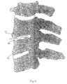
- Fig. 1 shows a lumbar application of the strain regulating fusion cage 1 according to one embodiment of the invention implanted in an intervertebral space 14 between two vertebral bodies 12;13.
- FIG. 2 a schematic representation of a strain regulation fusion cage according to the invention is shown.
- the cage 1 consists of a hollow cylinder with a central axis 2, an upper contact surface 3, a lower contact surface 4 and a coaxial cavity 5 extending between the upper 3 and the lower contact surface 4.
- two sectorial slots 8;9 perforate the circumferential sidewall 10 symmetrical to a first diameter and from diametrical opposite directions forming sectors 17;18 as shown in Fig. 4.
- Another two sectorial slots 6;7 (slot 7 not shown in the draft) perforate the circumferential sidewall 10 at a height H 2 that is closer to the upper contact surface 3 as the height H 1 .
- slots 8;9 arranged at the upper height H 2 also perforate the circumferential sidewall 10 symmetrical to a second diameter and from diametrical opposite directions forming sectors 15;16 as shown in Fig. 3.
- the slots 6;7 at the upper height H 2 arranged symmetrically to the second diameter are staggeredly arranged to the slots 8;9 at the lower height H 1 (fig. 4) arranged symmetrically to the first diameter whereby the first diameter is orthogonal to the second diameter.
- the slots 6;7 covering the sectors 15;16 at the upper height H 2 partially overlap the slots 8;9 covering the sectors 17;18 at the lower height H 1 .
- Such the struts 19;20;21;22 remaining between the slots 6;7;8;9 at the circumferential sidewall 10 may be elastically compressed by what means the cage 1 is compressed.
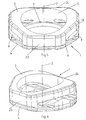
- Fig. 5 and 6 show the preferred embodiment of the strain regulation fusion cage 1 according to the invention.
- the cage 1 has a prism like exterior shape with an upper contact surface 3, a lower contact surface 4, a longitudinal axis 2 and an oval hole 5 coaxial to the longitudinal axis 2 and extending between the upper 3 and the lower contact surface 4.
- the cross section perpendicular to the longitudinal axis 2 shows an exterior circumference of the cage 1 that has the shape of an irregular polygon.
- the lower contact surface 4 is even and extending perpendicular to the longitudinal axis 2.
- Transverse to the front side 23 of the cage 1 the upper contact surface 3 is convexly shaped and converges towards the lower contact surface 4 at the front side 23 and the back side 24.
- the slots 6;7;8;9 perforate the circumferential sidewall 10 of the cage 1 at two planes perpendicular to the longitudinal axis 2 whereby the planes are situated at two different heights H 1 ;H 2 above the lower contact surface 4.
- Each plane contains two slots 6;7;8;9 that are situated diametrically opposite within the circumferential sidewall 10.
- the two slots 6;7 in the plane with the height H 1 which is closer to the lower contact surface 4 (fig. 7) are running parallel to the front side 23 of the cage 1 while the other two slots 8;9 in the plane with the height H 2 which is closer to the upper contact surface 3 (fig.
- each slot 6;7;8;9 covers another sector of the circumferential sidewall 10.
- the slots 6;7 in the plane closer to the lower contact surface 4 are only partially parallel shaped whereby these parallel sections provide the minimal width h 1 ;h 2 (fig. 7) of the slots 6;7.
- the slots 6;7 provide a curved shape.
- the slots 8;9 in the plane with the greater height H 2 are curvedly shaped whereby the curves form a small almost linelike area with the minimal width h 3 ;h 4 of the slots 7;8.
- Fig. 8 represents the strain regulating fusion cage 1 shown in fig. 5,6 and 7 whereby the cage 1 is compressed so far that the slots 6;7 lying in the plane closer to the lower contact surface 4 are closed at their sections with the minimal widths h 1 ;h 2 .
- Fig. 10 illustrates the spring rate of the cage 1 wherein the cage 1 coaxially provides a spring rate c1 upon compression until the first set of the slots 6;7 closes at their minimal widths h 1 ;h 2 and upon further compression provides a spring rate c 2 amounting 1 and 5 times as much as c 1 until the second set of slots 8;9 closes at their minimal widths h 3 ;h 4 causing a further increase of the stiffness of the cage 1 with an unknown gradient of the spring rate.
- Fig. 11 shows the strain regulating fusion cage 1 according to one embodiment of the invention implanted in an intervertebral space 14 between two vertebral bodies 12;13.
Claims (20)
- Fusionskäfig für den Zwischenwirbelraum umfassend einen prismatischen, konischen oder zylindrischen Käfig (1) mitA) einer Zentralachse (2);B) einer oberen und einer unteren Kontaktfläche (3;4) quer zur genannten Zentralachse (2), wobei die genannte obere und untere Kontaktfläche (3;4) zur Anlage an zwei benachbarte Wirbelkörper (12;13) bei in den Zwischenwirbelraum (14) implantiertem Käfig (1) bestimmt sind;C) einem zentralen Hohlraum (5) zur Aufnahme von Knochenpfropfenmaterial, welcher sich zwischen der genannten unteren Kontaktfläche (4) und der genannten oberen Kontaktfläche (3) durch den Käfig (1) erstreckt und eine koaxial zur genannten Zentralachse (2) angeordnete periphere Seitenwand (10) definiert; undD) einer Anzahl sektorieller Schlitze (6;7;8;9), welche die periphere Seitenwand (10) quer zur Zentralachse (2) durchdringen, wobeiE) die genannten Schlitze (6;7;8;9) eine Minimalweite (h1;h2;h3;h4) haben, so dass sich bei einer Kompression des Käfigs (1) entlang der Zentralachse (2) die genannten Schlitze (6;7;8;9) bei der Minimalweite (h1;h2;h3;h4) elastisch schliessen und damit die Steifigkeit des Käfigs (1) bei einer weiteren Kompression erhöhen.
- Fusionskäfig nach Anspruch 1, dadurch gekennzeichnet, dass sich die genannten Schlitze (6;7;8;9) bei einer Kompression des Käfigs (1) entlang der Zentralachse (2) bei der Minimalweite (h1;h2;h3;h4) bis zu einem Verformungsgrad zwischen 1000 µε und 50'000 µε elastisch schliessen und damit die Steifigkeit des Käfigs (1) bei einer weiteren Kompression erhöhen.
- Fusionskäfig nach Anspruch 2, dadurch gekennzeichnet, dass sich die genannten Schlitze (6;7;8;9) bei einer Kompression des Käfigs (1) entlang der Zentralachse (2) bei der Minimalweite (h1;h2;h3;h4) bis zu einem Verformungsgrad zwischen 3000 µε und 10'000 µε elastisch schliessen und damit die Steifigkeit des Käfigs (1) bei einer weiteren Kompression erhöhen.
- Fusionskäfig nach einem der Ansprüche 1 bis 3, dadurch gekennzeichnet, dass der Käfig (1) bei einer koaxialen Kompression eine Federrate c1 aufweist bis sich die Schlitze (6;7;8;9) bei ihrer Minimalweite (h1;h2;h3;h4) schliessen und bei einer weiteren Kompression eine Federrate c2 aufweist, welche zwischen dem 10-fachen und dem 100-fachen von c1 beträgt.
- Fusionskäfig nach einem der Ansprüche 1 bis 4, dadurch gekennzeichnet, dass der Käfig (1) bei einer koaxialen Kompression eine Federrate c1 aufweist bis sich ein erster Satz von Schlitzen (6;7;8;9) bei deren Minimalweite (h1;h2;h3;h4) schliesst und bei einer weiteren Kompression eine Federrate c2 aufweist, welche zwischen dem 1,0-fachen und dem 5-fachen von c1 beträgt bis sich ein zweiter Satz von Schlitzen (6;7;8;9) bei deren Minimalweite (h1;h2;h3;h4) schliesst und damit eine weitere Erhöhung der Steifigkeit des Käfigs (1) verursachen.
- Fusionskäfig nach einem der Ansprüche 1 bis 5, dadurch gekennzeichnet, dass die genannten Schlitze (6;7;8;9) die periphere Seitenwand (10) bei mindestens zwei unterschiedlichen Höhen (H1;H2) über der unteren Kontaktfläche (4) durchdringen.
- Fusionskäfig nach einem der Ansprüche 1 bis 6, dadurch gekennzeichnet, dass die genannten Schlitze (6;7;8;9) versetzt bei mindestens zwei unterschiedlichen Höhen (H1;H2) angeordnet sind.
- Fusionskäfig nach einem der Ansprüche 1 bis 7, dadurch gekennzeichnet, dass die genannten Schlitze (6;7;8;9) versetzt bei zwei unterschiedlichen Höhen (H1;H2) angeordnet sind.
- Fusionskäfig nach einem der Ansprüche 1 bis 8, dadurch gekennzeichnet, dass sich jeder Schlitz (6;7;8;9) über einen anderen Sektor (15;16;17;18) der genannten peripheren Seitenwand (10) erstreckt, so dass die Summe der Winkel aller Sektoren mindestens 360° beträgt.
- Fusionskäfig nach Anspruch 9, dadurch gekennzeichnet, dass sich die Sektoren (15;16;17;18) teilweise gegenseitig überlappen.
- Fusionskäfig nach einem der Ansprüche 1 bis 10, dadurch gekennzeichnet, dass die genannten Schlitze (6;7;8;9) eine Weite (h1;h2;h3;h4) aufweisen, so dass sich die Schlitze (6;7;8;9) bei einer Kompression des Käfigs (1) entlang der Zentralachse (2) bis zu einem Verformungsgrad zwischen 1000 µε und 50'000 µε bei der Minimalweite (h1;h2;h3;h4) elastisch schliessen.
- Fusionskäfig nach Anspruch 11, dadurch gekennzeichnet, dass die genannten Schlitze (6;7;8;9) eine Weite (h1;h2;h3;h4) aufweisen, so dass sich die Schlitze (6;7;8;9) bei einer Kompression des Käfigs (1) entlang der Zentralachse (2) bis zu einem Verformungsgrad zwischen 3000 µε und 10'000 µε bei der Minimalweite (h1;h2;h3;h4) elastisch schliessen.
- Fusionskäfig nach einem der Ansprüche 1 bis 12, dadurch gekennzeichnet, dass die Schlitze (6;7;8;9) eine Minimalweite (h1;h2;h3;h4) aufweisen, welche zwischen 0,02 bis 0,15 mm beträgt.
- Fusionskäfig nach einem der Ansprüche 1 bis 13, dadurch gekennzeichnet, dass der Käfig (1) zu einer die Zentralachse (2) enthaltenden Ebene symmetrisch ist.
- Fusionskäfig nach einem der Ansprüche 1 bis 14, dadurch gekennzeichnet, dass an jeder von zwei unterschiedlichen Höhen (H1;H2) zwei aus einer Gesamtheit von vier Schlitzen (6;7;8;9) vorgesehen sind.
- Fusionskäfig nach einem der Ansprüche 1 bis 15, dadurch gekennzeichnet, dass bei der Höhe (H1), welche näher bei der unteren Kontaktfläche (4) ist, zwei Schlitze (6;7) in gegenüberliegenden Sektoren (15;16) der genannten peripheren Seitenwand (10) angeordnet sind.
- Fusionskäfig nach einem der Ansprüche 1 bis 16, dadurch gekennzeichnet, dass bei der Höhe (H2), welche näher bei der oberen Kontaktfläche (3) ist, zwei Schlitze (6;7) in gegenüberliegenden Sektoren (15;16) der genannten peripheren Seitenwand (10) angeordnet sind.
- Fusionskäfig nach einem der Ansprüche 1 bis 17, dadurch gekennzeichnet, dass jeder der genannten Sektoren einen Winkel in einem Bereich zwischen 45° und 150°, vorzugsweise zwischen 90° und 120° einschliesst.
- Fusionskäfig nach einem der Ansprüche 1 bis 18, dadurch gekennzeichnet, dass das Volumen des Hohlraums (5) zwischen 30% und 70%, vorzugsweise zwischen 40% und 60% des Volumens beträgt, welches durch Aussenfläche des Käfigs (1) eingeschlossen wird.
- Fusionskäfig nach einem der Ansprüche 1 bis 19, dadurch gekennzeichnet, dass die Schlitze (6;7;8;9) im unbelasteten Zustand des Käfigs (1) eine variable Weite aufweisen.
Applications Claiming Priority (1)
| Application Number | Priority Date | Filing Date | Title |
|---|---|---|---|
| PCT/EP1998/006621 WO2000023014A1 (en) | 1998-10-20 | 1998-10-20 | Strain regulating fusion cage for spinal fusion surgery |
Publications (2)
| Publication Number | Publication Date |
|---|---|
| EP1123069A1 EP1123069A1 (de) | 2001-08-16 |
| EP1123069B1 true EP1123069B1 (de) | 2008-02-06 |
Family
ID=8167099
Family Applications (1)
| Application Number | Title | Priority Date | Filing Date |
|---|---|---|---|
| EP98965636A Expired - Lifetime EP1123069B1 (de) | 1998-10-20 | 1998-10-20 | Spannungsregulierender fusionskäfig für wirbelsäulenfusionschirurgie |
Country Status (13)
| Country | Link |
|---|---|
| US (1) | US6395035B2 (de) |
| EP (1) | EP1123069B1 (de) |
| JP (1) | JP4230666B2 (de) |
| KR (1) | KR100545011B1 (de) |
| AT (1) | ATE385411T1 (de) |
| AU (1) | AU739444B2 (de) |
| CA (1) | CA2347261C (de) |
| DE (1) | DE69839098T2 (de) |
| ES (1) | ES2301219T3 (de) |
| NZ (1) | NZ510441A (de) |
| TW (1) | TW396035B (de) |
| WO (1) | WO2000023014A1 (de) |
| ZA (1) | ZA996600B (de) |
Cited By (3)
| Publication number | Priority date | Publication date | Assignee | Title |
|---|---|---|---|---|
| US9216096B2 (en) | 2010-03-16 | 2015-12-22 | Pinnacle Spine Group, Llc | Intervertebral implants and related tools |
| US9380932B1 (en) | 2011-11-02 | 2016-07-05 | Pinnacle Spine Group, Llc | Retractor devices for minimally invasive access to the spine |
| US10070970B2 (en) | 2013-03-14 | 2018-09-11 | Pinnacle Spine Group, Llc | Interbody implants and graft delivery systems |
Families Citing this family (142)
| Publication number | Priority date | Publication date | Assignee | Title |
|---|---|---|---|---|
| US6964686B2 (en) | 1999-05-17 | 2005-11-15 | Vanderbilt University | Intervertebral disc replacement prosthesis |
| US7331994B2 (en) | 1999-05-17 | 2008-02-19 | Vanderbilt University | Intervertebral disc replacement prosthesis |
| US6579321B1 (en) * | 1999-05-17 | 2003-06-17 | Vanderbilt University | Intervertebral disc replacement prosthesis |
| US6520996B1 (en) * | 1999-06-04 | 2003-02-18 | Depuy Acromed, Incorporated | Orthopedic implant |
| FR2897259B1 (fr) | 2006-02-15 | 2008-05-09 | Ldr Medical Soc Par Actions Si | Cage intersomatique transforaminale a greffon de fusion intervetebrale et instrument d'implantation de la cage |
| US7169183B2 (en) * | 2000-03-14 | 2007-01-30 | Warsaw Orthopedic, Inc. | Vertebral implant for promoting arthrodesis of the spine |
| US6395033B1 (en) * | 2000-04-10 | 2002-05-28 | Tyco Healthcare Group Lp | Dynamic fusion mechanostat devices |
| FR2808995B1 (fr) | 2000-05-18 | 2003-02-21 | Aesculap Sa | Cage intersomatique a greffons unifies |
| FR2813519B1 (fr) * | 2000-09-07 | 2003-07-18 | Eurosurgical | Implant intersomatique souple |
| US6743257B2 (en) * | 2000-12-19 | 2004-06-01 | Cortek, Inc. | Dynamic implanted intervertebral spacer |
| US7169182B2 (en) | 2001-07-16 | 2007-01-30 | Spinecore, Inc. | Implanting an artificial intervertebral disc |
| US6673113B2 (en) * | 2001-10-18 | 2004-01-06 | Spinecore, Inc. | Intervertebral spacer device having arch shaped spring elements |
| US20020120335A1 (en) * | 2001-02-28 | 2002-08-29 | Angelucci Christopher M. | Laminoplasty implants and methods of use |
| US6719794B2 (en) * | 2001-05-03 | 2004-04-13 | Synthes (U.S.A.) | Intervertebral implant for transforaminal posterior lumbar interbody fusion procedure |
| US6974480B2 (en) | 2001-05-03 | 2005-12-13 | Synthes (Usa) | Intervertebral implant for transforaminal posterior lumbar interbody fusion procedure |
| FR2824261B1 (fr) * | 2001-05-04 | 2004-05-28 | Ldr Medical | Prothese de disque intervertebral et procede et outils de mise en place |
| FR2827156B1 (fr) * | 2001-07-13 | 2003-11-14 | Ldr Medical | Dispositif de cage vertebrale avec fixation modulaire |
| US6471725B1 (en) * | 2001-07-16 | 2002-10-29 | Third Millenium Engineering, Llc | Porous intervertebral distraction spacers |
| US6635087B2 (en) | 2001-08-29 | 2003-10-21 | Christopher M. Angelucci | Laminoplasty implants and methods of use |
| US7713302B2 (en) | 2001-10-01 | 2010-05-11 | Spinecore, Inc. | Intervertebral spacer device utilizing a spirally slotted belleville washer having radially spaced concentric grooves |
| US7771477B2 (en) | 2001-10-01 | 2010-08-10 | Spinecore, Inc. | Intervertebral spacer device utilizing a belleville washer having radially spaced concentric grooves |
| US7179295B2 (en) * | 2001-10-05 | 2007-02-20 | Nebojsa Kovacevic | Prosthetic shock absorber |
| US20030083749A1 (en) * | 2001-10-31 | 2003-05-01 | Kuslich Stephen D. | Corpectomy device |
| US6979353B2 (en) * | 2001-12-03 | 2005-12-27 | Howmedica Osteonics Corp. | Apparatus for fusing adjacent bone structures |
| ES2287460T3 (es) * | 2002-03-11 | 2007-12-16 | Spinal Concepts Inc. | Instrumentacion para implantar implantes de columna. |
| US6824278B2 (en) * | 2002-03-15 | 2004-11-30 | Memx, Inc. | Self-shadowing MEM structures |
| US8038713B2 (en) | 2002-04-23 | 2011-10-18 | Spinecore, Inc. | Two-component artificial disc replacements |
| US20080027548A9 (en) | 2002-04-12 | 2008-01-31 | Ferree Bret A | Spacerless artificial disc replacements |
| FR2846550B1 (fr) | 2002-11-05 | 2006-01-13 | Ldr Medical | Prothese de disque intervertebral |
| US7192447B2 (en) | 2002-12-19 | 2007-03-20 | Synthes (Usa) | Intervertebral implant |
| CN1774220A (zh) | 2003-02-14 | 2006-05-17 | 德普伊斯派尔公司 | 原位成型的椎间融合器械和方法 |
| US6908484B2 (en) * | 2003-03-06 | 2005-06-21 | Spinecore, Inc. | Cervical disc replacement |
| EP1635744A4 (de) * | 2003-03-06 | 2013-03-13 | Spinecore Inc | Instrumente und verfahren zur verwendung bei der implantation einer vorrichtung zum banscheibeneratz in der halswirbelsäule |
| US7918876B2 (en) | 2003-03-24 | 2011-04-05 | Theken Spine, Llc | Spinal implant adjustment device |
| EP1610730A1 (de) * | 2003-04-07 | 2006-01-04 | Cervitech, Inc. | Zwischenwirbel-gelenkprothese für die halswirbelsäule |
| US8012212B2 (en) * | 2003-04-07 | 2011-09-06 | Nuvasive, Inc. | Cervical intervertebral disk prosthesis |
| US20040267367A1 (en) * | 2003-06-30 | 2004-12-30 | Depuy Acromed, Inc | Intervertebral implant with conformable endplate |
| FR2858546B1 (fr) * | 2003-08-04 | 2006-04-28 | Spine Next Sa | Prothese de disque intervertebral |
| EP1673048B1 (de) * | 2003-10-17 | 2013-06-19 | Biedermann Technologies GmbH & Co. KG | Flexibles implantat |
| DE102004021861A1 (de) | 2004-05-04 | 2005-11-24 | Biedermann Motech Gmbh | Flexibler Platzhalter |
| US7837732B2 (en) * | 2003-11-20 | 2010-11-23 | Warsaw Orthopedic, Inc. | Intervertebral body fusion cage with keels and implantation methods |
| US20050149192A1 (en) * | 2003-11-20 | 2005-07-07 | St. Francis Medical Technologies, Inc. | Intervertebral body fusion cage with keels and implantation method |
| US7695517B2 (en) | 2003-12-10 | 2010-04-13 | Axiomed Spine Corporation | Apparatus for replacing a damaged spinal disc |
| US7550010B2 (en) | 2004-01-09 | 2009-06-23 | Warsaw Orthopedic, Inc. | Spinal arthroplasty device and method |
| US7771479B2 (en) | 2004-01-09 | 2010-08-10 | Warsaw Orthopedic, Inc. | Dual articulating spinal device and method |
| RU2354334C2 (ru) | 2004-02-04 | 2009-05-10 | Лдр Медикаль | Протез межпозвоночного диска |
| FR2865629B1 (fr) | 2004-02-04 | 2007-01-26 | Ldr Medical | Prothese de disque intervertebral |
| FR2869528B1 (fr) | 2004-04-28 | 2007-02-02 | Ldr Medical | Prothese de disque intervertebral |
| US7799081B2 (en) | 2004-09-14 | 2010-09-21 | Aeolin, Llc | System and method for spinal fusion |
| EP1796603A2 (de) * | 2004-09-23 | 2007-06-20 | Akiva Raphael Katz | Zwischen-bandscheiben-prothese |
| US20060111780A1 (en) * | 2004-11-22 | 2006-05-25 | Orthopedic Development Corporation | Minimally invasive facet joint hemi-arthroplasty |
| US8021392B2 (en) * | 2004-11-22 | 2011-09-20 | Minsurg International, Inc. | Methods and surgical kits for minimally-invasive facet joint fusion |
| US20060111779A1 (en) | 2004-11-22 | 2006-05-25 | Orthopedic Development Corporation, A Florida Corporation | Minimally invasive facet joint fusion |
| US20060111786A1 (en) * | 2004-11-22 | 2006-05-25 | Orthopedic Development Corporation | Metallic prosthetic implant for use in minimally invasive acromio-clavicular shoulder joint hemi-arthroplasty |
| WO2006058221A2 (en) | 2004-11-24 | 2006-06-01 | Abdou Samy M | Devices and methods for inter-vertebral orthopedic device placement |
| FR2879436B1 (fr) | 2004-12-22 | 2007-03-09 | Ldr Medical | Prothese de disque intervertebral |
| US7575598B2 (en) * | 2005-03-03 | 2009-08-18 | Cervical Xpand, Llc | Anterior lumbar intervertebral stabilizer |
| US9456907B1 (en) | 2005-03-24 | 2016-10-04 | Igip, Llc | Extendable spinal implant |
| US8673006B2 (en) * | 2005-03-24 | 2014-03-18 | Igip, Llc | Spinal implant |
| US8986383B2 (en) * | 2005-03-24 | 2015-03-24 | Igip, Llc | End cap and connector for a spinal implant |
| US8226718B2 (en) * | 2005-03-24 | 2012-07-24 | Cardinal Spine, Llc | Spinal implant and method of using spinal implant |
| US8361149B2 (en) | 2005-03-24 | 2013-01-29 | Cardinal Spine, Llc | Wedge-like spinal implant |
| US7435261B1 (en) * | 2005-03-24 | 2008-10-14 | Frank Castro | Spinal implant and method of using spinal implant |
| US8246683B2 (en) * | 2005-03-24 | 2012-08-21 | Cardinal Spine, Llc | Spinal implant |
| FR2887762B1 (fr) | 2005-06-29 | 2007-10-12 | Ldr Medical Soc Par Actions Si | Instrumentation d'insertion de prothese de disque intervertebral entre des vertebres |
| US20070016301A1 (en) * | 2005-07-14 | 2007-01-18 | Medical Device Concepts Llc. | Multi-axial interbody spacer device |
| FR2891135B1 (fr) | 2005-09-23 | 2008-09-12 | Ldr Medical Sarl | Prothese de disque intervertebral |
| US8192494B2 (en) * | 2005-09-26 | 2012-06-05 | K2M, Inc. | Posterior metal-on-metal disc replacement device and method |
| EP1943986B1 (de) * | 2005-10-26 | 2012-04-25 | BIEDERMANN MOTECH GmbH | Implantat mit einstückigem Drehgelenk |
| US8753399B2 (en) * | 2005-11-28 | 2014-06-17 | Stryker Spine | Dynamic interbody device |
| FR2893838B1 (fr) | 2005-11-30 | 2008-08-08 | Ldr Medical Soc Par Actions Si | Prothese de disque intervertebral et instrumentation d'insertion de la prothese entre les vertebres |
| US8236055B2 (en) * | 2005-12-16 | 2012-08-07 | Seaspine, Inc. | Intervertebral prosthesis for supporting adjacent vertebral bodies enabling the creation of soft fusion and method |
| US7811326B2 (en) | 2006-01-30 | 2010-10-12 | Warsaw Orthopedic Inc. | Posterior joint replacement device |
| US20080161920A1 (en) * | 2006-10-03 | 2008-07-03 | Warsaw Orthopedic, Inc. | Dynamizing Interbody Implant and Methods for Stabilizing Vertebral Members |
| US8092533B2 (en) * | 2006-10-03 | 2012-01-10 | Warsaw Orthopedic, Inc. | Dynamic devices and methods for stabilizing vertebral members |
| US20080167686A1 (en) * | 2007-01-05 | 2008-07-10 | Warsaw Orthopedic, Inc. | Non-Rigid Intervertebral Spacers |
| US8465546B2 (en) | 2007-02-16 | 2013-06-18 | Ldr Medical | Intervertebral disc prosthesis insertion assemblies |
| RU2443400C2 (ru) * | 2007-03-07 | 2012-02-27 | Ульрих Гмбх Унд Ко. Кг | Межпозвонковый имплантат с эластичным конструктивным элементом |
| US8864832B2 (en) * | 2007-06-20 | 2014-10-21 | Hh Spinal Llc | Posterior total joint replacement |
| FR2916956B1 (fr) | 2007-06-08 | 2012-12-14 | Ldr Medical | Cage intersomatique,prothese intervertebrale,dispositif d'ancrage et instrumentation d'implantation |
| US10821003B2 (en) | 2007-06-20 | 2020-11-03 | 3Spline Sezc | Spinal osteotomy |
| US8808380B2 (en) * | 2007-08-27 | 2014-08-19 | William Casey Fox | Method and apparatus for an osteotomy fixation or arthrodesis cage |
| FR2921820B1 (fr) * | 2007-10-05 | 2011-09-16 | Vincent Pointillart | Prothese intervertebrale |
| US20090248161A1 (en) * | 2008-03-20 | 2009-10-01 | K2M, Inc. | Artificial disc replacement device |
| EP2280666A4 (de) * | 2008-04-04 | 2013-07-03 | Thomas Haider Patents | Intervertebrale prothesen mit nachgiebigem füllmaterial zur unterstützung benachbarter wirbelkörper und verfahren |
| BRPI0914002A2 (pt) * | 2008-07-14 | 2015-10-27 | Synthes Gmbh | dispositivo espaçador inververtebral de amortecimento flexível |
| US20100042216A1 (en) * | 2008-08-15 | 2010-02-18 | Pioneer Surgical Technology, Inc. | Implant for Deploying Bone Graft Material and Methods Thereof |
| US8808294B2 (en) | 2008-09-09 | 2014-08-19 | William Casey Fox | Method and apparatus for a multiple transition temperature implant |
| WO2010078037A2 (en) * | 2008-12-17 | 2010-07-08 | Synthes Usa, Llc | Full-metal dampening intervertebral implant |
| CN102369332B (zh) * | 2008-12-31 | 2014-07-02 | 奥马尔·F·希门尼斯 | 带有弯曲构件的挠性接头结构 |
| EP2403548A1 (de) * | 2009-03-05 | 2012-01-11 | DSM IP Assets B.V. | Wirbelfusionskäfig |
| US8628577B1 (en) | 2009-03-19 | 2014-01-14 | Ex Technology, Llc | Stable device for intervertebral distraction and fusion |
| US9220547B2 (en) | 2009-03-27 | 2015-12-29 | Spinal Elements, Inc. | Flanged interbody fusion device |
| IN2012DN00952A (de) | 2009-07-22 | 2015-04-10 | Spinex Tec Llc | |
| KR101805935B1 (ko) | 2009-09-17 | 2017-12-06 | 엘디알 홀딩 코포레이션 | 연장가능 골 고정 부재를 구비한 추간 임플란트 |
| US8277509B2 (en) * | 2009-12-07 | 2012-10-02 | Globus Medical, Inc. | Transforaminal prosthetic spinal disc apparatus |
| US8764806B2 (en) | 2009-12-07 | 2014-07-01 | Samy Abdou | Devices and methods for minimally invasive spinal stabilization and instrumentation |
| US8636746B2 (en) | 2009-12-31 | 2014-01-28 | Spinex Tec, Llc | Methods and apparatus for insertion of vertebral body distraction and fusion devices |
| JP5647264B2 (ja) | 2009-12-31 | 2014-12-24 | エル・デ・エール・メデイカル | 固定装置、椎間インプラント、および移植器具 |
| US9402734B2 (en) | 2010-07-30 | 2016-08-02 | Igip, Llc | Spacer for spinal implant |
| DE102010040228A1 (de) * | 2010-09-03 | 2012-03-08 | Aces Gmbh | Knochenverankerungs- oder Verbindungseinrichtung die einen Dehnungsreiz induziert |
| KR20130097206A (ko) * | 2010-09-20 | 2013-09-02 | 신세스 게엠바하 | 순응형 임플란트 |
| KR101052833B1 (ko) * | 2010-10-28 | 2011-07-29 | 박경우 | 유연성을 갖는 척추체간 케이지 |
| CN101999950A (zh) * | 2010-12-02 | 2011-04-06 | 无锡尚瑞德医疗器械有限公司 | 椎间融合器 |
| US8845728B1 (en) | 2011-09-23 | 2014-09-30 | Samy Abdou | Spinal fixation devices and methods of use |
| US20130226240A1 (en) | 2012-02-22 | 2013-08-29 | Samy Abdou | Spinous process fixation devices and methods of use |
| FR2987256B1 (fr) | 2012-02-24 | 2014-08-08 | Ldr Medical | Dispositif d'ancrage pour implant intervertebral, implant intervertebral et instrumentation d'implantation |
| US9198767B2 (en) | 2012-08-28 | 2015-12-01 | Samy Abdou | Devices and methods for spinal stabilization and instrumentation |
| US9757247B2 (en) | 2012-10-01 | 2017-09-12 | DePuy Synthes Products, Inc. | Interbody fusion implant |
| US9320611B2 (en) * | 2012-10-20 | 2016-04-26 | Carlos Andres Rodriguez | Surgically implantable joint spacer |
| US10258480B1 (en) | 2012-10-20 | 2019-04-16 | Carlos Andres Rodriguez | Surgically implantable joint spacer |
| US9320617B2 (en) | 2012-10-22 | 2016-04-26 | Cogent Spine, LLC | Devices and methods for spinal stabilization and instrumentation |
| US9149366B2 (en) * | 2013-03-14 | 2015-10-06 | Warsaw Orthopedic, Inc. | Adaptable interbody implant and methods of use |
| US9610173B2 (en) | 2013-06-27 | 2017-04-04 | DePuy Synthes Products, Inc. | Vertebral body replacement apparatus |
| EP2832309B1 (de) | 2013-07-31 | 2018-03-07 | Biedermann Technologies GmbH & Co. KG | Implantat für Knochen oder Wirbel mit selbsteingeschränkter Flexibilität |
| US9486328B2 (en) | 2014-04-01 | 2016-11-08 | Ex Technology, Llc | Expandable intervertebral cage |
| US8940049B1 (en) | 2014-04-01 | 2015-01-27 | Ex Technology, Llc | Expandable intervertebral cage |
| EP3217926A4 (de) * | 2014-11-12 | 2018-10-24 | iOrthopedics, Inc. | Universell expandierbarer käfig |
| JP2018502693A (ja) | 2015-01-27 | 2018-02-01 | スパイナル・エレメンツ・インコーポレーテッド | 椎間関節インプラント |
| US20160270928A1 (en) * | 2015-03-18 | 2016-09-22 | Baui Biotech Co., Ltd. | Spinal spacer |
| CN104814816A (zh) * | 2015-05-20 | 2015-08-05 | 上海长征医院 | 自稳型极外侧入路椎间融合器 |
| US10857003B1 (en) | 2015-10-14 | 2020-12-08 | Samy Abdou | Devices and methods for vertebral stabilization |
| US10744000B1 (en) | 2016-10-25 | 2020-08-18 | Samy Abdou | Devices and methods for vertebral bone realignment |
| US10973648B1 (en) | 2016-10-25 | 2021-04-13 | Samy Abdou | Devices and methods for vertebral bone realignment |
| USD816844S1 (en) | 2017-06-29 | 2018-05-01 | American Medical Ortho Systems LLC | Lumbar interbody implant |
| USD841167S1 (en) | 2017-08-16 | 2019-02-19 | American Medical Ortho Systems LLC | Lumbar interbody implant |
| US10299938B1 (en) | 2018-09-07 | 2019-05-28 | John R. Ehteshami | Dynamic intervertebral spacer implant |
| US11234838B2 (en) | 2018-09-07 | 2022-02-01 | Additive Implants, Inc. | Dynamic intervertebral spacer implant |
| BR112021005206A2 (pt) | 2018-09-20 | 2021-06-08 | Spinal Elements, Inc. | dispositivo de implante espinhal |
| EP3856085A4 (de) * | 2018-09-26 | 2022-06-29 | Revivo Medical, LLC | Flexibles interkorporelles distanzstück und verfahren zu seiner verwendung |
| US11179248B2 (en) | 2018-10-02 | 2021-11-23 | Samy Abdou | Devices and methods for spinal implantation |
| US11129728B1 (en) | 2018-10-03 | 2021-09-28 | Guillermo Molina | Surgically implantable joint spacer |
| US11684482B2 (en) | 2018-12-20 | 2023-06-27 | Additive Implants, Inc. | Spondylolisthesis system and methods |
| US11497622B2 (en) | 2019-03-05 | 2022-11-15 | Ex Technology, Llc | Transversely expandable minimally invasive intervertebral cage and insertion and extraction device |
| US11234835B2 (en) | 2019-03-05 | 2022-02-01 | Octagon Spine Llc | Transversely expandable minimally invasive intervertebral cage |
| CA3151607A1 (en) * | 2019-09-24 | 2021-04-01 | Additive Implants, Inc. | Dynamic intervertebral spacer implant |
| US11123201B2 (en) | 2019-09-24 | 2021-09-21 | Additive Implants, Inc. | Intervertebral spacer |
| US11684485B1 (en) | 2020-02-04 | 2023-06-27 | Guillermo Molina | Surgically implantable joint spacer |
| KR102151554B1 (ko) * | 2020-05-19 | 2020-09-03 | (주)칼리스토 | 역동적 안정화를 위한 3d 프린팅 척추 케이지 |
| US11911284B2 (en) | 2020-11-19 | 2024-02-27 | Spinal Elements, Inc. | Curved expandable interbody devices and deployment tools |
| WO2022212694A1 (en) | 2021-04-02 | 2022-10-06 | Nuvasive, Inc. | Expansion driver |
| US11406509B1 (en) * | 2021-06-04 | 2022-08-09 | Additive Implants, Inc. | Cervical cage |
Family Cites Families (12)
| Publication number | Priority date | Publication date | Assignee | Title |
|---|---|---|---|---|
| US5458638A (en) * | 1989-07-06 | 1995-10-17 | Spine-Tech, Inc. | Non-threaded spinal implant |
| US5320644A (en) | 1991-08-30 | 1994-06-14 | Sulzer Brothers Limited | Intervertebral disk prosthesis |
| US5423817A (en) * | 1993-07-29 | 1995-06-13 | Lin; Chih-I | Intervertebral fusing device |
| FR2728159B1 (fr) | 1994-12-16 | 1997-06-27 | Tornier Sa | Prothese discale elastique |
| US5782919A (en) * | 1995-03-27 | 1998-07-21 | Sdgi Holdings, Inc. | Interbody fusion device and method for restoration of normal spinal anatomy |
| US5888227A (en) | 1995-10-20 | 1999-03-30 | Synthes (U.S.A.) | Inter-vertebral implant |
| US6143031A (en) | 1995-10-20 | 2000-11-07 | Synthes (U.S.A.) | Intervertebral implant with compressible shaped hollow element |
| US6503279B1 (en) | 1996-09-04 | 2003-01-07 | Synthes (Usa) | Intervertebral implant |
| FR2753368B1 (fr) * | 1996-09-13 | 1999-01-08 | Chauvin Jean Luc | Cage d'osteosynthese expansive |
| US5782832A (en) * | 1996-10-01 | 1998-07-21 | Surgical Dynamics, Inc. | Spinal fusion implant and method of insertion thereof |
| US5749916A (en) * | 1997-01-21 | 1998-05-12 | Spinal Innovations | Fusion implant |
| US6136031A (en) * | 1998-06-17 | 2000-10-24 | Surgical Dynamics, Inc. | Artificial intervertebral disc |
-
1998
- 1998-10-20 KR KR1020017004926A patent/KR100545011B1/ko not_active IP Right Cessation
- 1998-10-20 CA CA002347261A patent/CA2347261C/en not_active Expired - Fee Related
- 1998-10-20 ES ES98965636T patent/ES2301219T3/es not_active Expired - Lifetime
- 1998-10-20 DE DE69839098T patent/DE69839098T2/de not_active Expired - Lifetime
- 1998-10-20 NZ NZ510441A patent/NZ510441A/xx unknown
- 1998-10-20 AT AT98965636T patent/ATE385411T1/de not_active IP Right Cessation
- 1998-10-20 EP EP98965636A patent/EP1123069B1/de not_active Expired - Lifetime
- 1998-10-20 AU AU21510/99A patent/AU739444B2/en not_active Ceased
- 1998-10-20 WO PCT/EP1998/006621 patent/WO2000023014A1/en active IP Right Grant
- 1998-10-20 JP JP2000576792A patent/JP4230666B2/ja not_active Expired - Fee Related
-
1999
- 1999-09-01 TW TW088115014A patent/TW396035B/zh not_active IP Right Cessation
- 1999-10-19 ZA ZA9906600A patent/ZA996600B/xx unknown
-
2001
- 2001-04-11 US US09/829,995 patent/US6395035B2/en not_active Expired - Lifetime
Cited By (5)
| Publication number | Priority date | Publication date | Assignee | Title |
|---|---|---|---|---|
| US9216096B2 (en) | 2010-03-16 | 2015-12-22 | Pinnacle Spine Group, Llc | Intervertebral implants and related tools |
| US9649203B2 (en) | 2010-03-16 | 2017-05-16 | Pinnacle Spine Group, Llc | Methods of post-filling an intervertebral implant |
| US9788973B2 (en) | 2010-03-16 | 2017-10-17 | Pinnacle Spine Group, Llc | Spinal implant |
| US9380932B1 (en) | 2011-11-02 | 2016-07-05 | Pinnacle Spine Group, Llc | Retractor devices for minimally invasive access to the spine |
| US10070970B2 (en) | 2013-03-14 | 2018-09-11 | Pinnacle Spine Group, Llc | Interbody implants and graft delivery systems |
Also Published As
| Publication number | Publication date |
|---|---|
| AU2151099A (en) | 2000-05-08 |
| JP4230666B2 (ja) | 2009-02-25 |
| AU739444B2 (en) | 2001-10-11 |
| CA2347261C (en) | 2008-01-08 |
| NZ510441A (en) | 2002-10-25 |
| US6395035B2 (en) | 2002-05-28 |
| TW396035B (en) | 2000-07-01 |
| ATE385411T1 (de) | 2008-02-15 |
| EP1123069A1 (de) | 2001-08-16 |
| DE69839098D1 (de) | 2008-03-20 |
| WO2000023014A1 (en) | 2000-04-27 |
| KR20010107921A (ko) | 2001-12-07 |
| DE69839098T2 (de) | 2009-02-05 |
| ES2301219T3 (es) | 2008-06-16 |
| CA2347261A1 (en) | 2000-04-27 |
| KR100545011B1 (ko) | 2006-01-24 |
| US20010016774A1 (en) | 2001-08-23 |
| JP2002527196A (ja) | 2002-08-27 |
| ZA996600B (en) | 2000-05-02 |
Similar Documents
| Publication | Publication Date | Title |
|---|---|---|
| EP1123069B1 (de) | Spannungsregulierender fusionskäfig für wirbelsäulenfusionschirurgie | |
| US9554919B2 (en) | Intervertebral implant | |
| US5755798A (en) | Intervertebral implant | |
| JP4122134B2 (ja) | 人工椎間板 | |
| US8172902B2 (en) | Spinal interbody spacers | |
| EP0977526B1 (de) | Fusionsvorrichtung mit multivariabler höhe | |
| EP1850806B1 (de) | Künstliche bandscheibenanordnung | |
| US20070225810A1 (en) | Flexible cage spinal implant | |
| US20030083746A1 (en) | Vertebral spacer for spinal stabilization | |
| EP0577179A1 (de) | Implantat zum Fixieren benachbarter Wirbelknochen der Wirbelsäule | |
| NZ264176A (en) | Hollow tubular intersomatic implant for stabilisation of the vertebral column | |
| US20160324658A1 (en) | Intervertebral spacer that dynamically promotes bone growth | |
| US9198768B1 (en) | Enhanced artificial disk | |
| US9439773B2 (en) | Enhanced artificial disk | |
| US20070088439A1 (en) | Artificial disc with endplates having cages to promote bone fusion | |
| US11744713B2 (en) | Intervertebral spacer that dynamically promotes bone growth | |
| US8075620B1 (en) | Doughnut-like spinal implant | |
| KR20240040896A (ko) | 추간체 유합 보형재 |
Legal Events
| Date | Code | Title | Description |
|---|---|---|---|
| PUAI | Public reference made under article 153(3) epc to a published international application that has entered the european phase |
Free format text: ORIGINAL CODE: 0009012 |
|
| 17P | Request for examination filed |
Effective date: 20010224 |
|
| AK | Designated contracting states |
Kind code of ref document: A1 Designated state(s): AT BE CH DE DK ES FI FR GB GR IE IT LI NL PT SE |
|
| RAP1 | Party data changed (applicant data changed or rights of an application transferred) |
Owner name: SYNTHES GMBH |
|
| GRAP | Despatch of communication of intention to grant a patent |
Free format text: ORIGINAL CODE: EPIDOSNIGR1 |
|
| GRAS | Grant fee paid |
Free format text: ORIGINAL CODE: EPIDOSNIGR3 |
|
| GRAA | (expected) grant |
Free format text: ORIGINAL CODE: 0009210 |
|
| AK | Designated contracting states |
Kind code of ref document: B1 Designated state(s): AT BE CH DE DK ES FI FR GB GR IE IT LI NL PT SE |
|
| REG | Reference to a national code |
Ref country code: GB Ref legal event code: FG4D |
|
| REG | Reference to a national code |
Ref country code: CH Ref legal event code: EP |
|
| REG | Reference to a national code |
Ref country code: IE Ref legal event code: FG4D |
|
| REF | Corresponds to: |
Ref document number: 69839098 Country of ref document: DE Date of ref document: 20080320 Kind code of ref document: P |
|
| REG | Reference to a national code |
Ref country code: CH Ref legal event code: NV Representative=s name: DR. LUSUARDI AG |
|
| REG | Reference to a national code |
Ref country code: SE Ref legal event code: TRGR |
|
| REG | Reference to a national code |
Ref country code: HK Ref legal event code: WD Ref document number: 1036925 Country of ref document: HK |
|
| REG | Reference to a national code |
Ref country code: ES Ref legal event code: FG2A Ref document number: 2301219 Country of ref document: ES Kind code of ref document: T3 |
|
| PG25 | Lapsed in a contracting state [announced via postgrant information from national office to epo] |
Ref country code: FI Free format text: LAPSE BECAUSE OF FAILURE TO SUBMIT A TRANSLATION OF THE DESCRIPTION OR TO PAY THE FEE WITHIN THE PRESCRIBED TIME-LIMIT Effective date: 20080206 |
|
| NLV1 | Nl: lapsed or annulled due to failure to fulfill the requirements of art. 29p and 29m of the patents act | ||
| ET | Fr: translation filed | ||
| PG25 | Lapsed in a contracting state [announced via postgrant information from national office to epo] |
Ref country code: BE Free format text: LAPSE BECAUSE OF FAILURE TO SUBMIT A TRANSLATION OF THE DESCRIPTION OR TO PAY THE FEE WITHIN THE PRESCRIBED TIME-LIMIT Effective date: 20080206 |
|
| PG25 | Lapsed in a contracting state [announced via postgrant information from national office to epo] |
Ref country code: PT Free format text: LAPSE BECAUSE OF FAILURE TO SUBMIT A TRANSLATION OF THE DESCRIPTION OR TO PAY THE FEE WITHIN THE PRESCRIBED TIME-LIMIT Effective date: 20080707 Ref country code: NL Free format text: LAPSE BECAUSE OF FAILURE TO SUBMIT A TRANSLATION OF THE DESCRIPTION OR TO PAY THE FEE WITHIN THE PRESCRIBED TIME-LIMIT Effective date: 20080206 Ref country code: DK Free format text: LAPSE BECAUSE OF FAILURE TO SUBMIT A TRANSLATION OF THE DESCRIPTION OR TO PAY THE FEE WITHIN THE PRESCRIBED TIME-LIMIT Effective date: 20080206 |
|
| PLBE | No opposition filed within time limit |
Free format text: ORIGINAL CODE: 0009261 |
|
| STAA | Information on the status of an ep patent application or granted ep patent |
Free format text: STATUS: NO OPPOSITION FILED WITHIN TIME LIMIT |
|
| 26N | No opposition filed |
Effective date: 20081107 |
|
| PG25 | Lapsed in a contracting state [announced via postgrant information from national office to epo] |
Ref country code: IE Free format text: LAPSE BECAUSE OF NON-PAYMENT OF DUE FEES Effective date: 20081020 |
|
| PGFP | Annual fee paid to national office [announced via postgrant information from national office to epo] |
Ref country code: SE Payment date: 20091007 Year of fee payment: 12 Ref country code: ES Payment date: 20091117 Year of fee payment: 12 Ref country code: AT Payment date: 20091013 Year of fee payment: 12 |
|
| PG25 | Lapsed in a contracting state [announced via postgrant information from national office to epo] |
Ref country code: GR Free format text: LAPSE BECAUSE OF FAILURE TO SUBMIT A TRANSLATION OF THE DESCRIPTION OR TO PAY THE FEE WITHIN THE PRESCRIBED TIME-LIMIT Effective date: 20080507 |
|
| PG25 | Lapsed in a contracting state [announced via postgrant information from national office to epo] |
Ref country code: AT Free format text: LAPSE BECAUSE OF NON-PAYMENT OF DUE FEES Effective date: 20101020 |
|
| PG25 | Lapsed in a contracting state [announced via postgrant information from national office to epo] |
Ref country code: SE Free format text: LAPSE BECAUSE OF NON-PAYMENT OF DUE FEES Effective date: 20101021 |
|
| REG | Reference to a national code |
Ref country code: ES Ref legal event code: FD2A Effective date: 20111118 |
|
| PG25 | Lapsed in a contracting state [announced via postgrant information from national office to epo] |
Ref country code: ES Free format text: LAPSE BECAUSE OF NON-PAYMENT OF DUE FEES Effective date: 20101021 |
|
| REG | Reference to a national code |
Ref country code: FR Ref legal event code: PLFP Year of fee payment: 18 |
|
| PGFP | Annual fee paid to national office [announced via postgrant information from national office to epo] |
Ref country code: FR Payment date: 20150629 Year of fee payment: 18 |
|
| PGFP | Annual fee paid to national office [announced via postgrant information from national office to epo] |
Ref country code: CH Payment date: 20151012 Year of fee payment: 18 Ref country code: DE Payment date: 20151013 Year of fee payment: 18 Ref country code: GB Payment date: 20151014 Year of fee payment: 18 Ref country code: IT Payment date: 20151026 Year of fee payment: 18 |
|
| REG | Reference to a national code |
Ref country code: DE Ref legal event code: R119 Ref document number: 69839098 Country of ref document: DE |
|
| REG | Reference to a national code |
Ref country code: CH Ref legal event code: PL |
|
| GBPC | Gb: european patent ceased through non-payment of renewal fee |
Effective date: 20161020 |
|
| REG | Reference to a national code |
Ref country code: FR Ref legal event code: ST Effective date: 20170630 |
|
| PG25 | Lapsed in a contracting state [announced via postgrant information from national office to epo] |
Ref country code: LI Free format text: LAPSE BECAUSE OF NON-PAYMENT OF DUE FEES Effective date: 20161031 Ref country code: CH Free format text: LAPSE BECAUSE OF NON-PAYMENT OF DUE FEES Effective date: 20161031 Ref country code: FR Free format text: LAPSE BECAUSE OF NON-PAYMENT OF DUE FEES Effective date: 20161102 Ref country code: GB Free format text: LAPSE BECAUSE OF NON-PAYMENT OF DUE FEES Effective date: 20161020 Ref country code: DE Free format text: LAPSE BECAUSE OF NON-PAYMENT OF DUE FEES Effective date: 20170503 |
|
| PG25 | Lapsed in a contracting state [announced via postgrant information from national office to epo] |
Ref country code: IT Free format text: LAPSE BECAUSE OF NON-PAYMENT OF DUE FEES Effective date: 20161020 |