EP1122978A2 - Système de casque d'écoute à plusieurs canaux - Google Patents
Système de casque d'écoute à plusieurs canaux Download PDFInfo
- Publication number
- EP1122978A2 EP1122978A2 EP01102203A EP01102203A EP1122978A2 EP 1122978 A2 EP1122978 A2 EP 1122978A2 EP 01102203 A EP01102203 A EP 01102203A EP 01102203 A EP01102203 A EP 01102203A EP 1122978 A2 EP1122978 A2 EP 1122978A2
- Authority
- EP
- European Patent Office
- Prior art keywords
- listener
- speaker
- speakers
- headphone
- sound source
- Prior art date
- Legal status (The legal status is an assumption and is not a legal conclusion. Google has not performed a legal analysis and makes no representation as to the accuracy of the status listed.)
- Granted
Links
Images


Classifications
-
- H—ELECTRICITY
- H04—ELECTRIC COMMUNICATION TECHNIQUE
- H04S—STEREOPHONIC SYSTEMS
- H04S3/00—Systems employing more than two channels, e.g. quadraphonic
- H04S3/002—Non-adaptive circuits, e.g. manually adjustable or static, for enhancing the sound image or the spatial distribution
- H04S3/004—For headphones
-
- H—ELECTRICITY
- H04—ELECTRIC COMMUNICATION TECHNIQUE
- H04R—LOUDSPEAKERS, MICROPHONES, GRAMOPHONE PICK-UPS OR LIKE ACOUSTIC ELECTROMECHANICAL TRANSDUCERS; DEAF-AID SETS; PUBLIC ADDRESS SYSTEMS
- H04R5/00—Stereophonic arrangements
- H04R5/033—Headphones for stereophonic communication
-
- H—ELECTRICITY
- H04—ELECTRIC COMMUNICATION TECHNIQUE
- H04R—LOUDSPEAKERS, MICROPHONES, GRAMOPHONE PICK-UPS OR LIKE ACOUSTIC ELECTROMECHANICAL TRANSDUCERS; DEAF-AID SETS; PUBLIC ADDRESS SYSTEMS
- H04R2205/00—Details of stereophonic arrangements covered by H04R5/00 but not provided for in any of its subgroups
- H04R2205/024—Positioning of loudspeaker enclosures for spatial sound reproduction
-
- H—ELECTRICITY
- H04—ELECTRIC COMMUNICATION TECHNIQUE
- H04R—LOUDSPEAKERS, MICROPHONES, GRAMOPHONE PICK-UPS OR LIKE ACOUSTIC ELECTROMECHANICAL TRANSDUCERS; DEAF-AID SETS; PUBLIC ADDRESS SYSTEMS
- H04R2460/00—Details of hearing devices, i.e. of ear- or headphones covered by H04R1/10 or H04R5/033 but not provided for in any of their subgroups, or of hearing aids covered by H04R25/00 but not provided for in any of its subgroups
- H04R2460/13—Hearing devices using bone conduction transducers
-
- H—ELECTRICITY
- H04—ELECTRIC COMMUNICATION TECHNIQUE
- H04R—LOUDSPEAKERS, MICROPHONES, GRAMOPHONE PICK-UPS OR LIKE ACOUSTIC ELECTROMECHANICAL TRANSDUCERS; DEAF-AID SETS; PUBLIC ADDRESS SYSTEMS
- H04R5/00—Stereophonic arrangements
- H04R5/033—Headphones for stereophonic communication
- H04R5/0335—Earpiece support, e.g. headbands or neckrests
-
- H—ELECTRICITY
- H04—ELECTRIC COMMUNICATION TECHNIQUE
- H04S—STEREOPHONIC SYSTEMS
- H04S2420/00—Techniques used stereophonic systems covered by H04S but not provided for in its groups
- H04S2420/01—Enhancing the perception of the sound image or of the spatial distribution using head related transfer functions [HRTF's] or equivalents thereof, e.g. interaural time difference [ITD] or interaural level difference [ILD]
-
- H—ELECTRICITY
- H04—ELECTRIC COMMUNICATION TECHNIQUE
- H04S—STEREOPHONIC SYSTEMS
- H04S7/00—Indicating arrangements; Control arrangements, e.g. balance control
- H04S7/30—Control circuits for electronic adaptation of the sound field
- H04S7/307—Frequency adjustment, e.g. tone control
Definitions
- the present invention relates to a headphone system for reproducing a multi-channel acoustic signal.
- International Publication W095/20866 discloses a technology for filtering signals which are input to right and left speakers, so as to cause a sound source provided in front of or behind the listener to be recognized or perceived by the listener.
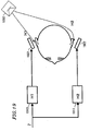
- Figure 19 shows a structure of a headphone system described in International Publication WO95/20866.
- the headphone system shown in Figure 19 includes a right ear speaker 1901 and a left ear speaker 1902 .
- the speakers 1901 and 1902 are fixed at positions distanced from the listener.
- the headphone system further includes filters 1910 and 1911 .
- Reference numeral 1960 represents a virtual sound source located behind the listener.
- H1 indicates a transfer function from the virtual sound source 1960 to the right ear of the listener.
- H2 indicates a transfer function from the virtual sound source 1960 to the left ear of the listener.
- Transfer function H1 is set in the filter 1910, and transfer function H2 is set in the filter 1911 .
- An input signal Z is input to the filters 1910 and 1911 .
- the output from the filter 1910 is input to the right ear speaker 1901
- the output from the filter 1911 is input to the left ear speaker 1902 .
- the listener can recognize the virtual sound source 1960 .
- a headphone system includes a headphone; and a signal processing circuit for outputting an acoustic signal to the headphone.
- the headphone includes a first speaker and a third speaker for a right ear of a listener, a second speaker and a fourth speaker for a left ear of the listener, and a support for supporting the first through fourth speakers so that the first and second speakers are located forward with respect to a vertical plane including a straight line connecting the hole of the right ear and the hole of the left ear of the listener, the third and fourth speakers are located rearward with respect to the vertical plane, and the first through fourth speakers are out of contact with the right ear and the left ear of the listener.
- the signal processing circuit outputs an acoustic signal, for causing the listener to recognize a front sound source located forward with respect to the listener, to the first and second speakers.
- the signal processing circuit outputs an acoustic signal, for causing the listener to recognize a rear sound source located rearward with respect to the listener, to the third and fourth speakers.
- the signal processing circuit outputs, among acoustic signals for causing the listener to recognize a rear sound source, acoustic signals having a frequency of a prescribed frequency fi or lower to the first and second speakers, and outputs acoustic signals having a frequency of the prescribed frequency fi or higher to the third and fourth speakers.
- the signal processing circuit outputs, among acoustic signals for causing the listener to recognize a front sound source, acoustic signals having a frequency of a prescribed frequency fi or higher to the first and second speakers, and outputs acoustic signals having a frequency of the prescribed frequency fi or lower to the third and fourth speakers.
- the first and second speakers are located rearward with respect to a vertical plane including a straight line connecting a right eye and a left eye of the listener.
- the third speaker is located so that an angle between a straight line straight ahead direction of the listener and a vertical line running through the center of a front surface of the third speaker is in the range of about 100 degrees to about 120 degrees
- the fourth speaker is located so that an angle between the straight line in the straight ahead direction of the listener and a vertical line running through the center of a front surface of the fourth speaker is in the range of about 100 degrees to about 120 degrees.
- the headphone further includes a low frequency-dedicated speaker for reproducing only audio signals in a low frequency band.
- the low frequency-dedicated speaker is located in the vicinity of a rear part of the head of the listener, when the headphone is worn.
- the low frequency-dedicated speaker is located in the vicinity of the top of the head of the listener, when the headphone is worn.
- the headphone further includes a vibration unit for vibrating based on a dedicated low frequency band signal used for reproducing only audio signals in a low frequency band, and the vibration unit is supported so as to be in close contact with a temporal region of the head of the listener, when the headphone is worn.
- the support includes a first supporting member for supporting the first and third speakers and a second supporting member for supporting the second and fourth speakers.
- the third speaker and the first supporting member are connected through a first connecting portion so that the third speaker is rotatable about the first connecting portion.
- the fourth speaker and the second supporting member are connected through a second connecting portion so that the fourth speaker is rotatable about the second connecting portion.
- the headphone further includes a first reflection plate for reflecting sound radiating from the third speaker and a second reflection plate for reflecting sound radiating from the fourth speaker.
- the third speaker is located so that a surface of a diaphragm of the third speaker includes a straight line connecting the hole of the right ear of the listener and the center of the third speaker, and the sound radiating from the third speaker and reflected by the first reflection plate reaches the right ear of the listener.
- the fourth speaker is located so that a surface of a diaphragm of the fourth speaker includes a straight line connecting the hole of the left ear of the listener and the center of the fourth speaker, and the sound radiating from the fourth speaker and reflected by the second reflection plate reaches the left ear of the listener.
- the invention described herein makes possible the advantage of providing a headphone system for reproducing a multi-channel acoustic signal so that the listener can correctly recognize or perceive a virtual sound source in front of or behind the listener regardless of the individual difference in the recognizing ability.
- a headphone system 101 according to a first example of the present invention will be described with reference to Figures 1A through 3.
- the headphone system 101 includes a headphone 201 and a signal processing circuit for outputting an acoustic signal to the headphone 201 .
- Figure 1A, 1B and 1C show a structure of the headphone 201 .
- Figure 1A is a top view
- Figure 1B is a front view
- Figure 1C is a side view of the headphone 201 .
- the headphone 201 includes right ear speakers 1 and 3 , left ear speakers 2 and 4 , and a support 8 for supporting the speakers 1 through 4 .
- the support 8 includes, for example, a headphone band 20 and speaker supporting members 30 and 31 .
- the support 8 supports the speakers 1 through 4 so as to fulfill the following conditions (1) through (3).
- the speakers 1 and 2 are located forward with respect to a vertical plane represented by the chain line 400 in Figures 1A and 1C .
- the vertical plane represented by the chain line 400 is defined as a vertical plane which includes a straight line connecting the right ear hole and the left ear hole of the listener.
- the vertical plane represented by the chain line 400 will be referred to as the "vertical plane 400" for convenience.
- Condition (3) The speakers 1 through 4 are located out of contact with the right and left ears of the listener.
- the speaker supporting member 30 supports the speakers 1 and 3
- the speaker supporting member 31 supports the speakers 2 and 4
- the speaker supporting members 30 and 31 are connected to each other by the headphone band 20 .
- the support 8 may have any other structure or shape as long as the support 8 supports the speakers 1 through 4 so as to fulfill the above conditions (1) through (3).
- the speakers 1 and 3 respectively have acoustically independent enclosures
- the speakers 2 and 4 also respectively have acoustically independent enclosures. Therefore, an acoustic signal from the speaker 1 and an acoustic signal from the speaker 3 independently reach the right ear of the listener along the shape of the head of the listener.
- an acoustic signal from the speaker 2 and an acoustic signal from the speaker 4 independently reach the left ear of the listener along the shape of the head of the listener. This means that information on the transfer function in front of and behind the individual listener is provided to the listener. As a result, the listener can correctly recognize a virtual sound source in front of or behind him/her regardless of the difference in different individuals' recognizing abilities.
- FIG. 2 shows a structure of a signal processing circuit 301a .
- the signal processing circuit 301a is one example of such a circuit usable in the headphone system 101 .
- the signal processing circuit 301a outputs an acoustic signal to the speakers 1 and 2 for causing the listener to recognize a sound source in front of the listener.
- reference numeral 50 represents a front center sound source indicated by the dotted line in front of the listener.
- the front center sound source 50 is not really present but is a virtual sound source which is recognized to be present by the listener.
- the front center sound source 50 will be referred to as the "virtual sound source 50" .
- the signal processing circuit 301a receives, as input signals, a front right signal (FR signal), a front left signal (FL signal), a front center signal (FC signal), a rear right signal (SR signal), and a rear left signal (SL signal).
- the signal processing circuit 301a processes these input signals to generate an acoustic signal, and outputs the acoustic signal to the headphone 201.
- the signal processing circuit 301a includes filters 10a and 11a , and adders 12a and 13a .
- the filter 10a processes the FC signal.
- the adder 12a adds the FC signal processed by the filter 10a and the FR signal. The addition result is output to the speaker 1 .
- the filter 11a also processes the FC signal.
- the adder 13a adds the FC signal processed by the filter 11a and the FL signal. The addition result is output to the speaker 2 .
- the SR signal is output to the speaker 3, and the SL signal is output to the speaker 4 .
- a transfer function X1 of the filter 10a and a transfer function Y1 of the filter 11a are designed to fulfill the following expressions (1) and (2).
- the listener can correctly recognize the virtual sound source 50.
- H1 is the transfer function from the virtual sound source 50 to the right ear hole of the listener
- H2 is the transfer function from the virtual sound source 50 to the left ear hole of the listener
- h1 is the transfer function from the speaker 1 to the right ear hole of the listener
- h2 is the transfer function from the speaker 1 to the left ear hole of the listener
- h3 is the transfer function from the speaker 2 to the right ear hole of the listener
- h4 is the transfer function from the speaker 2 to the left ear hole of the listener.
- X1 (h4 ⁇ H1-h3 ⁇ H2)/(h1 ⁇ h4-h2 ⁇ h3)
- Y1 (h1 ⁇ H2-h2 ⁇ H1)/(h1 ⁇ h4-h2 ⁇ h3)
- the transfer functions H1, H2, and h1 through h4 are measured with a specific listener.
- the specific listener may be an existent listener or a virtual listener.
- a transfer function H1' from the virtual sound source 50 to the right ear hole of the listener A is represented by expression (5).
- h1' is the transfer function from the speaker 1 to the right ear hole of the listener A
- h3' is the transfer function from the speaker 2 to the right ear hole of the listener A.
- H2' (1+ ⁇ h2) ⁇ H2
- the headphone system 101 can allow any listener to recognize the virtual sound source 50 more correctly than conventional headphone systems which merely implement the transfer functions H1 and H2 (for example, the conventional headphone system shown in Figure 19 ).
- FIG. 3 shows a signal processing circuit 301b.
- the signal processing circuit 301b is another example of such a circuit usable in the headphone system 101 .
- the signal processing circuit 301b outputs an acoustic signal to the speakers 3 and 4 for causing the listener to recognize the sound source behind the listener.
- reference numeral 6 0 represents a rear sound source indicated by the dotted line behind the listener.
- the rear sound source 60 is not really present but is a virtual sound source which is recognized to be present by the listener.
- the rear sound source 60 will be referred to as the "virtual sound source 60".
- the signal processing circuit 301b receives, as input signals, a front right signal (FR signal), a front left signal (FL signal), a rear center signal (SC signal), a rear right signal (SR signal), and a rear left signal (SL signal).
- the signal processing circuit 301b processes these input signals to generate an acoustic signal, and outputs the acoustic signal to the headphone 201 .
- the signal processing circuit 301b includes filters 10b and 11b , and adders 12b and 13b .
- the filter 10b processes the SC signal.
- the adder 12b adds the SC signal processed by the filter 10b and the SR signal. The addition result is output to the speaker 3 .
- the filter 11b also processes the SC signal.
- the adder 13b adds the SC signal processed by the filter 11b and the SL signal. The addition result is output to the speaker 4 .
- the FR signal is output to the speaker 1
- the FL signal is output to the speaker 2 .
- a transfer function X2 of the filter 10b and a transfer function Y2 of the filter 11b are designed to fulfill the following expressions (9) and (10).
- the listener can correctly recognize the virtual sound source 60 .
- H3 is the transfer function from the virtual sound source 60 to the right ear hole of the listener
- H4 is the transfer function from the virtual sound source 60 to the left ear hole of the listener
- h5 is the transfer function from the speaker 3 to the right ear hole of the listener
- h6 is the transfer function from the speaker 3 to the left ear hole of the listener
- h7 is the transfer function from the speaker 4 to the right ear hole of the listener
- h8 is the transfer function from the speaker 4 to the left ear hole of the listener.
- X2 is represented by expression (11) and Y2 is represented by expression (12).
- X2 (h8 ⁇ H3-h7 ⁇ H4)/(h5 ⁇ h8-h6 ⁇ h7)
- Y2 (h5 ⁇ H4-h6 ⁇ H3)/(h5 ⁇ h8-h6 ⁇ h7)
- an acoustic signal for causing the listener to recognize the sound source in front of the listener is reproduced using the speakers 1 and 2 located forward with respect to the vertical plane 400 ( Figures 1A and 1C ), and the sound source behind the listener is reproduced using the speakers 3 and 4 located rearward with respect to the vertical plane 400.
- the information on the sound source in front of the listener is provided to the listener through the individual transfer functions which are set in accordance with the shape of the head of the listener in the direction from the sound source to the listener.
- the information on the sound source behind the listener is also provided to the listener through the individual transfer functions which are set in accordance with the shape of the head of the listener in the direction from the sound source to the listener.
- the speakers 1 and 2 provided forward with respect to the vertical plane 400 are preferably located rearward with respect to a vertical plane represented by the chain line 401 .
- the vertical plane represented by the chain line 401 is defined as a plane which is parallel to the vertical plane 400 and includes a straight line connecting the right eye and the left eye of the listener.
- the vertical plane represented by the chain line 401 will be referred to as the "vertical plane 401" for convenience.
- the above-described location of the speakers 1 and 2 prevents the speakers 1 and 2 from being in the field of vision of the listener. As a result, the listener can enjoy the video displayed on the large-scale screen without being disturbed by the speakers 1 and 2 .
- a headphone system 102 according to a second example of the present invention will be described with reference to Figures 4A through 7 .
- the headphone system 102 includes a headphone 202 ( Figures 4A through 4C ) and a signal processing circuit 302 ( Figure 7 ) for outputting an acoustic signal to the headphone 202.
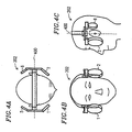
- Figure 4A , 4B and 4C show a structure of the headphone 202 .
- Figure 4A is a top view
- Figure 4B is a front view
- Figure 4C is a side view of the headphone 202.
- the headphone 202 includes right ear speakers 1 and 5 , left ear speakers 2 and 6 , and a support 8 for supporting the speakers 1, 2 , 5 and 6.
- the support 8 supports the speakers 1, 2, 5 and 6 so as to fulfill the following conditions (1) through (3).
- the speakers 1 and 2 are located forward with respect to the vertical plane 400 .
- Condition (2) The speakers 5 and 6 are located rearward with respect to the vertical plane 400.
- Condition (3) The speakers 1, 2, 5 and 6 are located out of contact with the right and left ears of the listener.
- acoustic signals having a frequency of a prescribed frequency fi or lower are reproduced using the speakers 1 and 2 located forward with respect to the vertical plane 400 .
- acoustic signals having a frequency of a prescribed frequency fi or higher are reproduced using the speakers 5 and 6 located rearward with respect to the vertical plane 400 .
- An acoustic signal having the prescribed frequency may be reproduced either using the speakers 1 and 2 or the speakers 5 and 6 .
- the prescribed frequency fi is preferably defined as the upper limit of the frequency band in which there is substantially no difference between the transfer function from a sound source in front of the listener to the right (or left) ear of the listener (hereinafter, referred to as the "front transfer function”) and the transfer function from a sound source behind the listener to the right (or left) ear of the listener (hereinafter, referred to as the "rear transfer function").
- the differences between the transfer functions is almost zero.
- the speakers 5 and 6 can be reduced in size and weight.
- the acoustic signals for causing the listener to recognize a sound source located in front of the listener are reproduced using the speakers 1 and 2 which are located forward with respect to the vertical plane 400.
- a difference between the front transfer function and the rear transfer function occurs because the shape of the head of the listener is asymmetric in the front-rear direction and the shape of the ears of the listener is asymmetric in the front-rear direction.
- the shape of the head and the shape of the ears are physically different in the front half and the rear half by merely a few centimeters or less.
- the above-mentioned prescribed frequency fi can be specified in consideration of the relationship between the wavelength and the frequency of the acoustic signals.
- the prescribed frequency fi is set at, for example, about 1 kHz to about 3 kHz.
- the difference in the size of the head or the ears among individuals is merely a few centimeters or less. Accordingly, the frequency at which the transfer functions starts to differ due to the individual difference almost matches the prescribed frequency fi.
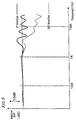
- Figure 5 is a graph illustrating one example of the front transfer function and the rear transfer function regarding a specific listener.
- the solid line represents an example of the head-related transfer function in the 0° direction (the direction straight ahead of the listener), and the dotted line represents an example of the head-related transfer function in the 180° direction (the direction directly behind the listener).
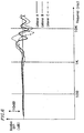
- Figure 6 is a graph illustrating one example of the individual difference in the head-related transfer function in the 0° direction (the direction straight ahead of the listeners).
- the solid line represents an example of the head-related transfer function of listener A
- the dotted line represents an example of the head-related transfer function of listener B
- the chain line represents an example of the head-related transfer function of listener C.
- the speakers 5 and 6 can have a smaller diaphragm and a more-lightweight magnetic circuit.
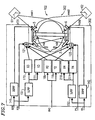
- Figure 7 shows a structure of the signal processing circuit 302 .
- the signal processing circuit 302 outputs, among acoustic signals for causing the listener to recognize a sound source behind the listener, acoustic signals having a frequency of fi or lower to the speakers 1 and 2 .
- the signal processing circuit 302 outputs, among the acoustic signals for causing the listener to recognize a sound source behind the listener, acoustic signals having the frequency of fi or higher to the speakers 5 and 6 .
- the signal processing circuit 302 includes high pass filters (HPF) 141 and 142 for allowing signals having a frequency component of fi or higher, and low pass filters (LPF) 151 and 152 for allowing signals having the frequency component of fi or lower.
- HPF high pass filters
- LPF low pass filters
- the signal processing circuit 302 also includes the filters 110, 111, 10b, 11b , 210 and 211 , and adders 121 and 122 .
- reference numerals 61 and 62 both represent virtual sound sources.
- the virtual sound source 61 is to the rear right of the listener, and the virtual sound source 62 is to the rear left of the listener.
- the SR signal is input to the speaker 5 through the HPF 141 .
- the SR signal is also input to the LPF 151 .
- the output from the LPF 151 is input to the filters 110 and 111 .
- the SL signal is input to the speaker 6 through the HPF 142.
- the SL signal is also input to the LPF 152 .
- the output from the LPF 152 is input to the filters 210 and 211.
- the SC signal is input to the filters 10b and 11b .
- the adder 121 adds the FR signal, the output from the filter 110 , the output from the filter 10b , and the output from the filter 210. The addition result is output to the speaker 1 .
- the adder 122 adds the FL signal, the output from the filter 111 , the output from the filter 11b , and the output from the filter 211 .
- the addition result is output to the speaker 2 .
- a transfer function X3 of the filter 110 and a transfer function Y3 of the filter 111 are designed to fulfill the following expressions (13) and (14). By thus designing the transfer functions X3 and Y3, the listener can correctly recognize the virtual sound source 61.
- X3 (h4 ⁇ H31-h3 ⁇ H41)/(h1 ⁇ h4-h2 ⁇ h3)
- Y3 (h1 ⁇ H41-h2 ⁇ H31)/(h1 ⁇ h4-h2 ⁇ h3)
- H31 is the transfer function from the virtual sound source 61 to the right ear hole of the listener
- H41 is the transfer function from the virtual sound source 61 to the left ear hole of the listener.
- a transfer function X4 of the filter 210 and a transfer function Y4 of the filter 211 are designed to fulfill expressions (15) and (16). By thus designing the transfer functions X4 and Y4, the listener can correctly recognize the virtual sound source 62.
- X4 (h4 ⁇ H32-h3 ⁇ H42)/(h1 ⁇ h4-h2 ⁇ h3)
- Y4 (h1 ⁇ H42-h2 ⁇ H32)/(h1 ⁇ h4-h2 ⁇ h3)
- H32 is the transfer function from the virtual sound source 62 to the left ear hole of the listener
- H42 is the transfer function from the virtual sound source 62 to the right ear hole of the listener.
- a headphone system 103 according to a third example of the present invention will be described with reference to Figures 8A through 9.
- FIG 9 shows a structure of the headphone system 103.
- the headphone system 103 includes a headphone 203 and a signal processing circuit 303 for outputting an acoustic signal to the headphone 203 .
- Figure 8A, 8B and 8C show a structure of the headphone 203 .
- Figure 8A is a top view
- Figure 8B is a front view
- Figure 8C is a side view of the headphone 203.
- the headphone 203 includes right ear speakers 1 and 5 , left ear speakers 2 and 6, and a support 8 for supporting the speakers 1, 2 , 5 and 6.
- the support 8 supports the speakers 1, 2, 5 and 6 so as to fulfill the following conditions (1) through (3).
- the speakers 1 and 2 are located forward with respect to the vertical plane 400 .
- Condition (3) The speakers 1, 2, 5 and 6 are located out of contact with the right and left ears of the listener.
- acoustic signals having a frequency of the prescribed frequency fi or lower are reproduced using the speakers 5 and 6 located rearward with respect to the vertical plane 400 .
- acoustic signals having a frequency of the prescribed frequency fi or higher are reproduced using the speakers 1 and 2 located forward with respect to the vertical plane 400 .
- the prescribed frequency fi is set in a similar manner to that according to the second example.
- the speakers 1 and 2 can be reduced in size and weight.
- the acoustic signals for causing the listener to recognize a sound source located behind the listener are reproduced using the speakers 5 and 6 which are located rearward with respect to the vertical plane 400.
- Figure 9 shows a structure of the signal processing circuit 303 .
- the signal processing circuit 303 outputs, among acoustic signals for causing the listener to recognize a sound source located in front of the listener, acoustic signals having a frequency of fi or higher to the speakers 1 and 2.
- the signal processing circuit 302 outputs, among the acoustic signals for causing the listener to recognize a sound source located in front of the listener, acoustic signals having a frequency of fi or lower to the speakers 5 and 6 .
- the signal processing circuit 303 includes a high pass filters (HPF) 41 for allowing signals having a frequency component of fi or higher, and a low pass filter (LPF) 51 for allowing signals having the frequency component of fi or lower, in addition to the HPFs 141 and 142 and the LPFs 151 and 152 .
- the signal processing circuit 303 also includes the filters 110, 111 , 10a , 11a , 210 and 211 , and adders 123 , 124, 125 and 126 .
- the FL signal is input to the HPF 141 .
- the output from the HPF 141 is input to the adder 125.
- the FL signal is also input to the LPF 151 .
- the output from the LPF 151 is input to the filters 110 and 111 .
- the FR signal is input to the HPF 142.
- the output from the HPF 142 is input to the adder 126.
- the FL signal is also input to the LPF 152.
- the output from the LPF 152 is input to the filters 210 and 211 .
- the FC signal is input to the HPF 41 and the LPF 51.
- the output from the HPF 41 is input to the filters 10a and lla.
- the output from the HPF 51 is input to the adders 123 and 124.
- the adder 125 adds the output from the HPF 141 and the output from the filter 10a , and outputs the addition result to the speaker 2 .
- the adder 123 adds the SL signal, the output from the filter 110 , the output from the LPF 51, and the output from the filter 210 ; and outputs the addition result to the speaker 6.
- the adder 124 adds the output from the filter 111 , the output from the LPF 51 , the output from the filter 211 , and the SR signal; and outputs the addition result to the speaker 5 .
- the adder 126 adds the output from the HPF 142 and the output from the filter lla, and outputs the addition result to the speaker 1.
- a headphone system according to a fourth example of the present invention will be described with reference to Figures 10A through Figure 14B .
- the headphone system includes a headphone 204 and a signal processing circuit (not shown) for outputting an acoustic signal to the headphone 204 .
- the headphone 204 includes a low frequency-dedicated speaker 7 for only reproducing acoustic signals in a low frequency band, in addition to the elements described in the first through third examples.
- the speakers are located out of contact with the ears of the listener.
- the reproduction level of the acoustic signals in the low frequency band is likely to be lowered.
- the low frequency-dedicated speaker 7 is provided for compensating for such a reduction in the reproduction level of the acoustic signals.
- the headphone 204 can have the low frequency-dedicated speaker 7 at various positions thereof.
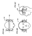
- Figures 10A , 10B and 10C show an example of providing the low frequency-dedicated speaker 7 in the vicinity of an upper rear part of the head of the listener.
- the headphone 204 includes a support assisting member 21 attached to the headphone band 20.
- the support assisting member 21 supports the low frequency-dedicated speaker 7 so as to be located in the vicinity of the upper rear part of the head of the listener.
- Figures 11A , 11B and 11C show an example of providing the low frequency-dedicated speaker 7 in the vicinity of the top of the head of the listener.
- the low frequency-dedicated speaker 7 is directly attached to the headphone band 20 so as to be located in the vicinity of the top of the head of the listener.
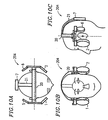
- Figures 12A, 12B and 12C show an example of providing the low frequency-dedicated speaker 7 in the vicinity of a lower rear part of the head of the listener.
- the headphone 204 includes a support assisting member 22 which is attachable on the shoulders of the listener.
- the support assisting member 22 supports the low frequency-dedicated speaker 7 so as to be located in the vicinity of the lower rear part of the head of the listener.
- the contact area of the support assisting member 21 and the head of the listener is larger in order to stabilize the low frequency-dedicated speaker 7 .
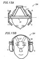
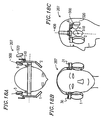
- Figures 13A and 13B show a support assisting member 21' having an improved shape so as to increase the contact area with the head of the listener.
- Figures 14A and 14B show a support assisting member 21" having another improved shape so as to increase the contact area with the head of the listener.
- the signal processing circuit is structured to output to the low frequency-dedicated speaker 7 a signal for reproducing only the acoustic signals in the low frequency band.
- the reduction in the low frequency reproduction ability of the speakers which are located out of contact with the ears of the listener can be compensated for by providing a low frequency-dedicated speaker.
- a headphone system according to a fifth example of the present invention will be described with reference to Figures 15A, 15B and 15C .
- the headphone system includes a headphone 205 and a signal processing circuit (not shown) for outputting an acoustic signal to the headphone 205 .
- Figures 15A, 15B and 15C are a top view, a front view and a side view of the headphone 205 .
- the headphone system according to the fifth example includes vibration units 10 and 11 in addition to the elements of the headphones 201 through 203 described in the first through third examples.
- the vibration units 10 and 11 vibrate based on a dedicated low frequency band signal used for reproducing only the audio signals in a low frequency band.
- the speakers are located out of contact with the ears of the listener.
- the reproduction level of the acoustic signals in the low frequency band is likely to be lowered.
- the vibration units 10 and 11 are provided for compensating for such a reduction in the reproduction level of the acoustic signals.
- acoustic signals in a wide frequency band can be satisfactorily reproduced by the headphone 205.
- the vibration unit 10 is provided between the speaker supporting member 30 and one temporal region of the head of the listener, and the vibration unit 11 is provided between the speaker supporting member 31 and the other temporal region of the head of the listener.
- the speaker supporting member 30 supports the speakers 1 and 5 .
- the speaker supporting member 31 supports the speakers 2 and 6 .
- the speaker supporting members 30 and 31 are connected to each other through a headphone band 20 .
- the vibration units 10 and 11 are provided to be in close contact with the temporal regions of the head.
- the vibration of the vibration units 10 and 11 is conveyed to the bones of skull. As a result, bone conduction is generated.
- the listener can recognize the sound in the low frequency band.
- the headphone 205 has another advantage that since the vibration units 10 and 11 are provided to be in close contact with the temporal regions of the head, the headphone 205 is unlikely to slip down from the head of the listener.
- the signal processing circuit included in the headphone system according to the fifth example is structured to output a dedicated low frequency band signal to the vibration units 10 and 11.
- the reduction in the low frequency ability of the speakers which are located out of contact with the ears of the listener can be compensated for by providing the vibration units.
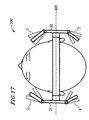
- a headphone system according to a sixth example of the present invention will be described with reference to Figures 16 and 17 .
- the headphone system includes a headphone 206 and a signal processing circuit (not shown) for outputting an acoustic signal to the headphone 206.
- the headphone 206 has the same structure as that of any of the headphones 201 through 205 described in the first through fifth examples.
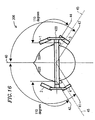
- the speakers 3 and 4 are located rearward with respect to the vertical plane 400 so that the angle made between a straight line 40 , which is in the straight ahead direction of the listener (i.e., perpendicular to the vertical plane 400 ), and vertical lines 45 which, respectively, run through the centers of the front surfaces of the speakers 3 and 4 and are vertical to the front surfaces of the speakers 3 and 4 is in the range of about 100 degrees and about 120 degrees.
- the listener can recognize the rear sound source in the range of about 100 degrees and about 120 degrees from the straight line 40. This matches the standards BS.775 recommended by the International Telecommunication Union (ITU). Due to such a structure, the listener can recognize the rear sound source while sensing a preferable expansion of the sound.
- ITU International Telecommunication Union
- the speakers 3 and 4 are provided so that the angle made between the straight line 40 and the line running through the center of the front surface of the speakers 3 and 4 is about 110 degrees.
- the line 41 makes an angle of about 110 degrees with the straight line 40 and runs through the center of the head of the listener.
- the line 42 makes an angle of about 110 degrees with the straight line 40 and runs through the left ear hole of the listener.
- the speaker 4 is provided so that the line running through the center of the front surface of the speaker 4 is parallel to the lines 41 and 42.
- the line 43 makes an angle of about 110 degrees with the straight line 40 and runs through the center of the head of the listener.
- the line 44 makes an angle of about 110 degrees with the straight line 40 and runs through the right ear hole of the listener.
- the speaker 3 is provided so that the line running through the center of the front surface of the speaker 3 is parallel to the lines 43 and 44.
- Figure 17 shows a headphone 206 ' including an angle adjusting mechanism for adjusting the angle of the speakers 1 through 4 with respect to the listener.
- the headphone 206' includes a speaker supporting member 30 for supporting the speakers 1 and 3 , and a speaker supporting member 31 for supporting the speakers 2 and 4 .
- the speaker 1 and the speaker supporting member 30 are connected to each other through a hinge mechanism.
- the speaker 3 and the speaker supporting member 30 , the speaker 2 and the speaker supporting member 31 , and the speaker 4 and the speaker supporting member 31 are connected to each other through a hinge mechanism.
- the speakers 1 through 4 are rotatably supported about the connecting portions.
- the angle made between the straight head direction of the listener (the direction of the straight line 40 in Figure 16 ) and the line running through the center of the front surface of each of the speakers 1 through 4 can be set to be in the above-described preferable range.
- Such a mechanism also facilitates compensating for the undesirable deviation of the positions of the speakers and the ears of the listener due to the difference between different individuals.
- the listener can select his/her favorite sound field perception by adjusting the angle made by the straight ahead direction of the listener and the lines running through the centers of the front surfaces of the speakers 1 and 2 located forward with respect to the vertical plane 400 .
- the speakers 1 and 2 may be fixed with respect to the listener while the speakers 3 and 4 are adjustable.
- the speakers 3 and 4 may be fixed with respect to the listener while the speakers 1 and 2 are adjustable.
- the listener can recognize the sound field more accurately in multi-channel reproduction by setting in a prescribed range the angle made between the straight ahead direction of the listener and the lines running through the centers of the front surfaces of the speakers 3 and 4 which are located rearward with respect to the listener.
- a headphone system according to a seventh example of the present invention will be described with reference to Figures 18A , 18B and 18C.
- the headphone system according to the seventh example includes a headphone 207 and a signal processing circuit (not shown) for outputting an acoustic signal to the headphone 207 .
- Figures 18A, 18B and 18C are a top view, a front view and a side view of the headphone 207 .
- the headphone 207 includes a reflection plate 510 for reflecting the sound radiating from the speaker 6 .
- the speaker 6 is located so that the surface of the diaphragm of the speaker 6 includes a straight line 500 which connects the left ear hole of the listener and the center of the speaker 6 .
- the sound radiating from the speaker 6 is reflected by the reflection plate 510 and reaches the left ear of the listener.
- the sound transmitted forward with respect to the speaker 6 along the straight line 500 and the sound transmitted rearward with respect to the speaker 6 along the straight line 500 counteract each other and are reduced in amplitude on the straight line 500 .
- the sound, radiating from the speaker 6 in the straight ahead direction of the speaker 6 and reflected by the reflection plate 510 reaches the left ear of the listener without being reduced. Therefore, the listener can recognize the sound as if the sound radiated from a virtual speaker 520.
- the rear surface of the speaker 6 is acoustically open.
- Another reflecting plate may be provided for reflecting the sound radiating from the speaker 5 , and the speaker 5 may be positioned like the speaker 6 .
- the listener can recognize the acoustic image of the virtual speaker which is relatively far from the head of the listener, using the speakers 5 and 6 located near the head of the listener.
- the headphone 207 can be reduced in size.
- a first speaker and a second speaker are provided forward with respect to a vertical plane including the straight line connecting the right ear hole and the left ear hole of the listener, and a third speaker and a fourth speaker are provided rearward with respect to the vertical plane.
- the first through fourth speakers are located out of contact with the right and left ears of the listener.
- an acoustic signal from the first speaker and an acoustic signal from the third speaker separately reach the right ear of the listener along the shape of his/her head.
- An acoustic signal from the second speaker and an acoustic signal from the fourth speaker separately reach the left ear of the listener along the shape of his/her head.
- acoustic signals having a frequency of a prescribed frequency fi or lower are output to the first and second speakers, and acoustic signals having a frequency of the prescribed frequency fi or higher are output to the third and fourth speakers.
- the third and fourth speakers can be reduced in size and weight.
- the first and second speakers are preferably located rearward with respect to a vertical plane including a straight line connecting the right eye and the left eye of the listener.
Applications Claiming Priority (2)
| Application Number | Priority Date | Filing Date | Title |
|---|---|---|---|
| JP2000025786 | 2000-02-02 | ||
| JP2000025786A JP4281937B2 (ja) | 2000-02-02 | 2000-02-02 | ヘッドホンシステム |
Publications (3)
| Publication Number | Publication Date |
|---|---|
| EP1122978A2 true EP1122978A2 (fr) | 2001-08-08 |
| EP1122978A3 EP1122978A3 (fr) | 2004-01-07 |
| EP1122978B1 EP1122978B1 (fr) | 2005-10-05 |
Family
ID=18551596
Family Applications (1)
| Application Number | Title | Priority Date | Filing Date |
|---|---|---|---|
| EP01102203A Expired - Lifetime EP1122978B1 (fr) | 2000-02-02 | 2001-01-31 | Système de casque d'écoute à plusieurs canaux |
Country Status (7)
| Country | Link |
|---|---|
| US (1) | US6944309B2 (fr) |
| EP (1) | EP1122978B1 (fr) |
| JP (1) | JP4281937B2 (fr) |
| KR (1) | KR100426513B1 (fr) |
| CN (1) | CN100442943C (fr) |
| DE (1) | DE60113741T2 (fr) |
| ID (1) | ID29556A (fr) |
Cited By (4)
| Publication number | Priority date | Publication date | Assignee | Title |
|---|---|---|---|---|
| WO2017123580A1 (fr) * | 2016-01-12 | 2017-07-20 | Bose Corporation | Casque d'écoute |
| EP3122062A4 (fr) * | 2014-03-19 | 2017-10-11 | Sony Corporation | Dispositif de sortie acoustique |
| CN109379659A (zh) * | 2018-11-16 | 2019-02-22 | 王美金 | 一种用于虚拟与增强现实的人机交互声学定向耳机 |
| EP3404931A4 (fr) * | 2017-03-03 | 2019-10-09 | Lok Hin Hui | Équipement stéréo portatif |
Families Citing this family (36)
| Publication number | Priority date | Publication date | Assignee | Title |
|---|---|---|---|---|
| US20040237111A1 (en) * | 2001-06-26 | 2004-11-25 | Spiro Iraclianos | Multimedia and entertainment system for an automobile |
| KR20030091177A (ko) * | 2002-05-24 | 2003-12-03 | 강구태 | 청음장치 |
| US20050058311A1 (en) * | 2003-09-15 | 2005-03-17 | Branom Lee Arthur | Stereo headphone |
| JP4988717B2 (ja) | 2005-05-26 | 2012-08-01 | エルジー エレクトロニクス インコーポレイティド | オーディオ信号のデコーディング方法及び装置 |
| EP1905002B1 (fr) * | 2005-05-26 | 2013-05-22 | LG Electronics Inc. | Procede et appareil de decodage d'un signal audio |
| WO2007005119A2 (fr) * | 2005-07-05 | 2007-01-11 | Ultimate Ears, Llc | Filtre separateur actif et interface sans fil pour recepteurs et casques intra-auriculaires a pilotes multiples |
| JP4787331B2 (ja) * | 2006-01-19 | 2011-10-05 | エルジー エレクトロニクス インコーポレイティド | メディア信号の処理方法及び装置 |
| CA2637722C (fr) * | 2006-02-07 | 2012-06-05 | Lg Electronics Inc. | Appareil et procede de codage/decodage de signal |
| US7983437B2 (en) * | 2008-01-04 | 2011-07-19 | Hammond Wong | Earphone set with detachable speakers or subwoofers |
| US8335331B2 (en) * | 2008-01-18 | 2012-12-18 | Microsoft Corporation | Multichannel sound rendering via virtualization in a stereo loudspeaker system |
| WO2009101622A2 (fr) | 2008-02-11 | 2009-08-20 | Bone Tone Communications Ltd. | Système sonore et procédé pour former un son |
| US20090245549A1 (en) * | 2008-03-26 | 2009-10-01 | Microsoft Corporation | Identification of earbuds used with personal media players |
| JP4678432B2 (ja) * | 2008-10-31 | 2011-04-27 | 日本ビクター株式会社 | 撮像装置 |
| US9197978B2 (en) | 2009-03-31 | 2015-11-24 | Panasonic Intellectual Property Management Co., Ltd. | Sound reproduction apparatus and sound reproduction method |
| US8654997B2 (en) * | 2010-03-18 | 2014-02-18 | Donald Eugene Meehan, Sr. | Personal miniaturized loudspeaker placement platform |
| JP5716451B2 (ja) * | 2011-02-25 | 2015-05-13 | ソニー株式会社 | ヘッドホン装置およびヘッドホン装置の音声再生方法 |
| KR101863831B1 (ko) * | 2012-01-20 | 2018-06-01 | 로무 가부시키가이샤 | 연골 전도부를 갖는 휴대 전화 |
| CN103631574A (zh) * | 2012-08-27 | 2014-03-12 | 富泰华工业(深圳)有限公司 | 电子装置及其通过发声装置分辨应用程序的方法 |
| US10986454B2 (en) | 2014-01-06 | 2021-04-20 | Alpine Electronics of Silicon Valley, Inc. | Sound normalization and frequency remapping using haptic feedback |
| US8767996B1 (en) | 2014-01-06 | 2014-07-01 | Alpine Electronics of Silicon Valley, Inc. | Methods and devices for reproducing audio signals with a haptic apparatus on acoustic headphones |
| US8977376B1 (en) | 2014-01-06 | 2015-03-10 | Alpine Electronics of Silicon Valley, Inc. | Reproducing audio signals with a haptic apparatus on acoustic headphones and their calibration and measurement |
| CN111432300B (zh) | 2014-03-19 | 2022-03-22 | 科帕动物保健公司 | 用于颈部背面的感官刺激或监视装置 |
| US10021487B2 (en) * | 2014-09-19 | 2018-07-10 | Axent Wear Inc. | Headsets with external speakers with predetermined shapes and designs |
| EP3211916A4 (fr) * | 2014-10-20 | 2018-06-20 | Sony Corporation | Dispositif de reproduction audio |
| US9609436B2 (en) * | 2015-05-22 | 2017-03-28 | Microsoft Technology Licensing, Llc | Systems and methods for audio creation and delivery |
| US10536782B2 (en) * | 2015-07-02 | 2020-01-14 | Carl L. C. Kah, Jr. | External ear insert for hearing enhancement |
| US9838787B1 (en) * | 2016-06-06 | 2017-12-05 | Bose Corporation | Acoustic device |
| JP6799141B2 (ja) * | 2016-08-01 | 2020-12-09 | マジック リープ, インコーポレイテッドMagic Leap,Inc. | 空間化オーディオを用いた複合現実システム |
| CN106954139A (zh) * | 2017-04-19 | 2017-07-14 | 音曼(北京)科技有限公司 | 一种联合耳机和扬声器的声场渲染方法及系统 |
| US10699691B1 (en) * | 2017-06-29 | 2020-06-30 | Amazon Technologies, Inc. | Active noise cancellation for bone conduction speaker of a head-mounted wearable device |
| US10206053B1 (en) * | 2017-11-09 | 2019-02-12 | Harman International Industries, Incorporated | Extra-aural headphone device and method |
| CN116193325A (zh) * | 2018-07-23 | 2023-05-30 | 杜比实验室特许公司 | 通过多个近场换能器渲染双耳音频 |
| USD934197S1 (en) | 2019-03-24 | 2021-10-26 | Buddy Snow | Headphones |
| KR102565131B1 (ko) * | 2019-05-31 | 2023-08-08 | 디티에스, 인코포레이티드 | 포비에이티드 오디오 렌더링 |
| US11178479B2 (en) | 2019-06-15 | 2021-11-16 | Matthew Thomas | Bone conduction headset |
| KR102615750B1 (ko) * | 2021-10-03 | 2023-12-19 | 민훈 | 비접촉 소음제거 헤드폰 |
Citations (5)
| Publication number | Priority date | Publication date | Assignee | Title |
|---|---|---|---|---|
| US3984885A (en) * | 1974-03-15 | 1976-10-12 | Matsushita Electric Industrial Co., Ltd. | 4-Channel headphones |
| DE2608908A1 (de) * | 1976-03-04 | 1977-09-08 | Johannes Dipl Phys Dr Lensing | Stereokopfhoerer zur uebertragung der vorne-ortung |
| US4821323A (en) * | 1988-02-19 | 1989-04-11 | Papiernik Raymond S | Stereo headphone |
| US5684879A (en) * | 1996-01-19 | 1997-11-04 | Verdick; Michael | Combination head mounted speaker assembly and multi-channel audio processing system |
| US5761314A (en) * | 1994-01-27 | 1998-06-02 | Sony Corporation | Audio reproducing apparatus and headphone |
Family Cites Families (11)
| Publication number | Priority date | Publication date | Assignee | Title |
|---|---|---|---|---|
| JPS4939002B1 (fr) * | 1970-12-05 | 1974-10-22 | ||
| JPS4939002A (fr) | 1972-08-23 | 1974-04-11 | ||
| AT323823B (de) * | 1973-06-19 | 1975-07-25 | Akg Akustische Kino Geraete | Schallsender nach dem zweinegsystem, insbesondere für kopphörer |
| DE2608090B2 (de) | 1976-02-27 | 1978-08-10 | Siemens Ag, 1000 Berlin Und 8000 Muenchen | Verfahren und Anordnung zur Steuerung des an der ankommenden c-Ader in einer Fernmeldeeinrichtung angeschlossenen Aufprüfkreises und Haltekreises |
| US5333206A (en) * | 1992-03-18 | 1994-07-26 | Koss Corporation | Dual element headphone |
| KR0124394B1 (ko) * | 1994-04-27 | 1997-12-01 | 김광호 | 헤드폰 |
| KR19990000358A (ko) | 1997-06-05 | 1999-01-15 | 윤종용 | 비소 이온 주입공정의 진행방법 |
| KR19990000358U (ko) * | 1997-06-09 | 1999-01-15 | 구자홍 | 서라운드 사운드 이어폰 장치 |
| JPH11275696A (ja) * | 1998-01-22 | 1999-10-08 | Sony Corp | ヘッドホン、ヘッドホンアダプタおよびヘッドホン装置 |
| US6356644B1 (en) * | 1998-02-20 | 2002-03-12 | Sony Corporation | Earphone (surround sound) speaker |
| JP3623127B2 (ja) * | 1998-12-25 | 2005-02-23 | 松下電器産業株式会社 | ヘッドホン装置 |
-
2000
- 2000-02-02 JP JP2000025786A patent/JP4281937B2/ja not_active Expired - Fee Related
-
2001
- 2001-01-31 EP EP01102203A patent/EP1122978B1/fr not_active Expired - Lifetime
- 2001-01-31 DE DE60113741T patent/DE60113741T2/de not_active Expired - Fee Related
- 2001-02-01 CN CNB011113359A patent/CN100442943C/zh not_active Expired - Fee Related
- 2001-02-02 KR KR10-2001-0005033A patent/KR100426513B1/ko not_active IP Right Cessation
- 2001-02-02 ID IDP20010109D patent/ID29556A/id unknown
- 2001-02-02 US US09/776,480 patent/US6944309B2/en not_active Expired - Lifetime
Patent Citations (5)
| Publication number | Priority date | Publication date | Assignee | Title |
|---|---|---|---|---|
| US3984885A (en) * | 1974-03-15 | 1976-10-12 | Matsushita Electric Industrial Co., Ltd. | 4-Channel headphones |
| DE2608908A1 (de) * | 1976-03-04 | 1977-09-08 | Johannes Dipl Phys Dr Lensing | Stereokopfhoerer zur uebertragung der vorne-ortung |
| US4821323A (en) * | 1988-02-19 | 1989-04-11 | Papiernik Raymond S | Stereo headphone |
| US5761314A (en) * | 1994-01-27 | 1998-06-02 | Sony Corporation | Audio reproducing apparatus and headphone |
| US5684879A (en) * | 1996-01-19 | 1997-11-04 | Verdick; Michael | Combination head mounted speaker assembly and multi-channel audio processing system |
Cited By (9)
| Publication number | Priority date | Publication date | Assignee | Title |
|---|---|---|---|---|
| EP3122062A4 (fr) * | 2014-03-19 | 2017-10-11 | Sony Corporation | Dispositif de sortie acoustique |
| WO2017123580A1 (fr) * | 2016-01-12 | 2017-07-20 | Bose Corporation | Casque d'écoute |
| US9794677B2 (en) | 2016-01-12 | 2017-10-17 | Bose Corporation | Headphone |
| CN108702561A (zh) * | 2016-01-12 | 2018-10-23 | 伯斯有限公司 | 耳机 |
| EP3468222A1 (fr) * | 2016-01-12 | 2019-04-10 | Bose Corporation | Casque d'écoute |
| CN108702561B (zh) * | 2016-01-12 | 2020-06-09 | 伯斯有限公司 | 耳机 |
| EP3849207A1 (fr) * | 2016-01-12 | 2021-07-14 | Bose Corporation | Unité audio |
| EP3404931A4 (fr) * | 2017-03-03 | 2019-10-09 | Lok Hin Hui | Équipement stéréo portatif |
| CN109379659A (zh) * | 2018-11-16 | 2019-02-22 | 王美金 | 一种用于虚拟与增强现实的人机交互声学定向耳机 |
Also Published As
| Publication number | Publication date |
|---|---|
| JP4281937B2 (ja) | 2009-06-17 |
| ID29556A (id) | 2001-09-06 |
| CN100442943C (zh) | 2008-12-10 |
| KR20010078278A (ko) | 2001-08-20 |
| JP2001218293A (ja) | 2001-08-10 |
| EP1122978B1 (fr) | 2005-10-05 |
| DE60113741D1 (de) | 2006-02-16 |
| US20010031062A1 (en) | 2001-10-18 |
| DE60113741T2 (de) | 2006-06-08 |
| EP1122978A3 (fr) | 2004-01-07 |
| US6944309B2 (en) | 2005-09-13 |
| KR100426513B1 (ko) | 2004-04-13 |
| CN1311622A (zh) | 2001-09-05 |
Similar Documents
| Publication | Publication Date | Title |
|---|---|---|
| EP1122978B1 (fr) | Système de casque d'écoute à plusieurs canaux | |
| EP1680941B1 (fr) | Son d'ambiance audio multivoie provenant de hauts-parleurs situes a l'avant | |
| US8027476B2 (en) | Sound reproduction apparatus and sound reproduction method | |
| US8170245B2 (en) | Virtual multichannel speaker system | |
| EP2009957B1 (fr) | Dispositif haut-parleur | |
| EP1370115A2 (fr) | Système de contrôle d'image sonores | |
| EP3439330B1 (fr) | Réglage de la hauteur perçue d'une image audio sur un écran de cinéma solide | |
| EP1696702B1 (fr) | Dispositif portatif avec une image stéréo améliorée | |
| CN107039029B (zh) | 头盔中具有有源噪声控制的声音再现 | |
| US7817812B2 (en) | Compact audio reproduction system with large perceived acoustic size and image | |
| EP1455554B1 (fr) | Circuit et programme traîtement des signaux audio multicanaux et dispositif de réproduction des dits signaux | |
| EP1775994A1 (fr) | Dispositif de localisation d'image sonore | |
| JP2009049844A (ja) | 骨伝導ヘッドホン装置 | |
| US20230276188A1 (en) | Surround Sound Location Virtualization | |
| EP0833545B1 (fr) | Dispositif de haut-parleur | |
| KR100873639B1 (ko) | 헤드폰에서 출력되는 음상을 외재화하는 장치 및 방법. | |
| WO2009113333A1 (fr) | Dispositif de traitement de signaux et procédé de traitement de signaux | |
| JP2004357075A (ja) | 映像音響再生装置 | |
| EP2139267A1 (fr) | Dispositif de reproduction acoustique | |
| JP2003087900A (ja) | スピーカ装置 | |
| CN116367050A (zh) | 处理音频信号的方法、存储介质、电子设备和音频设备 | |
| JP2008252500A (ja) | フロントサラウンド再生装置 | |
| JP2006157106A (ja) | 音響再生装置及び音響再生システム |
Legal Events
| Date | Code | Title | Description |
|---|---|---|---|
| PUAI | Public reference made under article 153(3) epc to a published international application that has entered the european phase |
Free format text: ORIGINAL CODE: 0009012 |
|
| AK | Designated contracting states |
Kind code of ref document: A2 Designated state(s): AT BE CH CY DE DK ES FI FR GB GR IE IT LI LU MC NL PT SE TR |
|
| AX | Request for extension of the european patent |
Free format text: AL;LT;LV;MK;RO;SI |
|
| PUAL | Search report despatched |
Free format text: ORIGINAL CODE: 0009013 |
|
| AK | Designated contracting states |
Kind code of ref document: A3 Designated state(s): AT BE CH CY DE DK ES FI FR GB GR IE IT LI LU MC NL PT SE TR |
|
| AX | Request for extension of the european patent |
Extension state: AL LT LV MK RO SI |
|
| 17P | Request for examination filed |
Effective date: 20040218 |
|
| 17Q | First examination report despatched |
Effective date: 20040405 |
|
| AKX | Designation fees paid |
Designated state(s): DE FR GB |
|
| GRAP | Despatch of communication of intention to grant a patent |
Free format text: ORIGINAL CODE: EPIDOSNIGR1 |
|
| GRAS | Grant fee paid |
Free format text: ORIGINAL CODE: EPIDOSNIGR3 |
|
| GRAA | (expected) grant |
Free format text: ORIGINAL CODE: 0009210 |
|
| AK | Designated contracting states |
Kind code of ref document: B1 Designated state(s): DE FR GB |
|
| REG | Reference to a national code |
Ref country code: GB Ref legal event code: FG4D |
|
| REF | Corresponds to: |
Ref document number: 60113741 Country of ref document: DE Date of ref document: 20060216 Kind code of ref document: P |
|
| ET | Fr: translation filed | ||
| PLBE | No opposition filed within time limit |
Free format text: ORIGINAL CODE: 0009261 |
|
| STAA | Information on the status of an ep patent application or granted ep patent |
Free format text: STATUS: NO OPPOSITION FILED WITHIN TIME LIMIT |
|
| 26N | No opposition filed |
Effective date: 20060706 |
|
| PGFP | Annual fee paid to national office [announced via postgrant information from national office to epo] |
Ref country code: DE Payment date: 20070125 Year of fee payment: 7 |
|
| PGFP | Annual fee paid to national office [announced via postgrant information from national office to epo] |
Ref country code: GB Payment date: 20070131 Year of fee payment: 7 |
|
| PGFP | Annual fee paid to national office [announced via postgrant information from national office to epo] |
Ref country code: FR Payment date: 20070109 Year of fee payment: 7 |
|
| GBPC | Gb: european patent ceased through non-payment of renewal fee |
Effective date: 20080131 |
|
| PG25 | Lapsed in a contracting state [announced via postgrant information from national office to epo] |
Ref country code: DE Free format text: LAPSE BECAUSE OF NON-PAYMENT OF DUE FEES Effective date: 20080801 |
|
| REG | Reference to a national code |
Ref country code: FR Ref legal event code: ST Effective date: 20081029 |
|
| PG25 | Lapsed in a contracting state [announced via postgrant information from national office to epo] |
Ref country code: GB Free format text: LAPSE BECAUSE OF NON-PAYMENT OF DUE FEES Effective date: 20080131 |
|
| PG25 | Lapsed in a contracting state [announced via postgrant information from national office to epo] |
Ref country code: FR Free format text: LAPSE BECAUSE OF NON-PAYMENT OF DUE FEES Effective date: 20080131 |