EP1122566A2 - Système de connexion pour fibre optique - Google Patents
Système de connexion pour fibre optique Download PDFInfo
- Publication number
- EP1122566A2 EP1122566A2 EP01102320A EP01102320A EP1122566A2 EP 1122566 A2 EP1122566 A2 EP 1122566A2 EP 01102320 A EP01102320 A EP 01102320A EP 01102320 A EP01102320 A EP 01102320A EP 1122566 A2 EP1122566 A2 EP 1122566A2
- Authority
- EP
- European Patent Office
- Prior art keywords
- plug
- fiber optic
- assemblies
- connection system
- housing
- Prior art date
- Legal status (The legal status is an assumption and is not a legal conclusion. Google has not performed a legal analysis and makes no representation as to the accuracy of the status listed.)
- Granted
Links
Images


Classifications
-
- G—PHYSICS
- G02—OPTICS
- G02B—OPTICAL ELEMENTS, SYSTEMS OR APPARATUS
- G02B6/00—Light guides; Structural details of arrangements comprising light guides and other optical elements, e.g. couplings
- G02B6/24—Coupling light guides
- G02B6/36—Mechanical coupling means
- G02B6/38—Mechanical coupling means having fibre to fibre mating means
- G02B6/3807—Dismountable connectors, i.e. comprising plugs
- G02B6/3869—Mounting ferrules to connector body, i.e. plugs
-
- G—PHYSICS
- G02—OPTICS
- G02B—OPTICAL ELEMENTS, SYSTEMS OR APPARATUS
- G02B6/00—Light guides; Structural details of arrangements comprising light guides and other optical elements, e.g. couplings
- G02B6/24—Coupling light guides
- G02B6/36—Mechanical coupling means
- G02B6/38—Mechanical coupling means having fibre to fibre mating means
- G02B6/3807—Dismountable connectors, i.e. comprising plugs
- G02B6/3873—Connectors using guide surfaces for aligning ferrule ends, e.g. tubes, sleeves, V-grooves, rods, pins, balls
- G02B6/3874—Connectors using guide surfaces for aligning ferrule ends, e.g. tubes, sleeves, V-grooves, rods, pins, balls using tubes, sleeves to align ferrules
- G02B6/3878—Connectors using guide surfaces for aligning ferrule ends, e.g. tubes, sleeves, V-grooves, rods, pins, balls using tubes, sleeves to align ferrules comprising a plurality of ferrules, branching and break-out means
-
- G—PHYSICS
- G02—OPTICS
- G02B—OPTICAL ELEMENTS, SYSTEMS OR APPARATUS
- G02B6/00—Light guides; Structural details of arrangements comprising light guides and other optical elements, e.g. couplings
- G02B6/24—Coupling light guides
- G02B6/36—Mechanical coupling means
- G02B6/38—Mechanical coupling means having fibre to fibre mating means
- G02B6/3807—Dismountable connectors, i.e. comprising plugs
- G02B6/3887—Anchoring optical cables to connector housings, e.g. strain relief features
- G02B6/3888—Protection from over-extension or over-compression
-
- G—PHYSICS
- G02—OPTICS
- G02B—OPTICAL ELEMENTS, SYSTEMS OR APPARATUS
- G02B6/00—Light guides; Structural details of arrangements comprising light guides and other optical elements, e.g. couplings
- G02B6/24—Coupling light guides
- G02B6/36—Mechanical coupling means
- G02B6/38—Mechanical coupling means having fibre to fibre mating means
- G02B6/3807—Dismountable connectors, i.e. comprising plugs
- G02B6/381—Dismountable connectors, i.e. comprising plugs of the ferrule type, e.g. fibre ends embedded in ferrules, connecting a pair of fibres
- G02B6/3818—Dismountable connectors, i.e. comprising plugs of the ferrule type, e.g. fibre ends embedded in ferrules, connecting a pair of fibres of a low-reflection-loss type
- G02B6/3821—Dismountable connectors, i.e. comprising plugs of the ferrule type, e.g. fibre ends embedded in ferrules, connecting a pair of fibres of a low-reflection-loss type with axial spring biasing or loading means
-
- G—PHYSICS
- G02—OPTICS
- G02B—OPTICAL ELEMENTS, SYSTEMS OR APPARATUS
- G02B6/00—Light guides; Structural details of arrangements comprising light guides and other optical elements, e.g. couplings
- G02B6/24—Coupling light guides
- G02B6/36—Mechanical coupling means
- G02B6/38—Mechanical coupling means having fibre to fibre mating means
- G02B6/3807—Dismountable connectors, i.e. comprising plugs
- G02B6/3833—Details of mounting fibres in ferrules; Assembly methods; Manufacture
- G02B6/3851—Ferrules having keying or coding means
-
- G—PHYSICS
- G02—OPTICS
- G02B—OPTICAL ELEMENTS, SYSTEMS OR APPARATUS
- G02B6/00—Light guides; Structural details of arrangements comprising light guides and other optical elements, e.g. couplings
- G02B6/24—Coupling light guides
- G02B6/36—Mechanical coupling means
- G02B6/38—Mechanical coupling means having fibre to fibre mating means
- G02B6/3807—Dismountable connectors, i.e. comprising plugs
- G02B6/389—Dismountable connectors, i.e. comprising plugs characterised by the method of fastening connecting plugs and sockets, e.g. screw- or nut-lock, snap-in, bayonet type
- G02B6/3893—Push-pull type, e.g. snap-in, push-on
Definitions
- the present invention relates generally to a fiber optic connection system and, more particularly, to a fiber optic plug wherein a housing and mating insert cooperate to secure the fiber optic cable and plug pre-assemblies with respect to the plug.
- the present invention is a fiber optic connection system including a fiber optic plug adapted to mate and lock with a fiber optic connector.
- the term "connector” means (i) a jack whereby two fiber optic cables are coupled together and (ii) an interface housing, such as a transceiver, whereby a fiber optic cable is coupled to a piece of hardware.
- the plug includes a housing, a pair of plug pre-assemblies and an insert.
- the housing has curved or arcuate side walls that partially define two passageways.
- the plug pre-assemblies reside within the passageways.
- the housing and insert snap-lock together and cooperatively define a mechanism to position and maintain the plug pre-assemblies. That is, the housing and insert cooperatively secure the assemblies with respect to the plug.
- the housing and insert further cooperate to secure the fiber optic cable with respect to the plug for proper loading, i . e ., the strengthener of the cable (such as aramid yarn) is secured to the plug.
- Another object of the present invention is an inexpensive, readily produced connection system for fiber optic cable. Still another object is a fiber optic connection wherein the plug and connector interlocked to provide connection stability and to substantially avoid connection "play.”
- Yet another object of the present invention is fiber optic plug including a housing and insert snap-locked thereto to substantially facilitate assembly and repair. It is also an object to provide a plug for a fiber optic cable connection system, wherein a housing and mated insert cooperatively secure the plug pre-assemblies and strengthener of the cable to the plug.
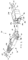
- FIGURES 1 - 4 A first preferred embodiment of the present invention is shown in FIGURES 1 - 4 as a fiber optic connection system, generally designated 10.
- the system 10 operatively couples first and second fiber optic cables 12, 14 in an interlocked state.
- the cable 12 includes side-by-side optical fibers 16, 18, and a cable strengthener, generally designated 20 and typically an aramid yarn.
- the optical fibers 16, 18 are individually wrapped with strengthening elements 22, 24, respectively, shown in FIGURE 1 as a solid strand jacket and in FIGURES 3 and 5 as separated loose strands.
- the second cable 14 similarly includes fiber elements 26, 28 and strengthening elements 30, 32.
- the system 10 includes a fiber optic plug 34, structurally affixed or secured to the cable strengthener 20 and, more particularly, the strengthening elements 22, 24, and a fiber optic jack 36 structurally affixed to the strengthening elements 30, 32.
- the jack 36 receives the plug 34 in the interlocked state to selectively couple the bare glass fibers of the optical fibers 16, 18 to the bare glass fibers of the fiber elements 26, 28, respectively, as is well known in the art.
- the plug 34 includes a housing 38, first and second plug pre-assemblies, generally designated 40, 42 in FIGURE 2, and an insert 44, assembled as shown.
- the housing 38 is generally rectangular and has a front housing end 46 and a rear housing end 48.
- the jack 36 receives at the front housing end 46; the insert 44 is received at the rear housing end 48.
- the housing 38 includes a substantially planar top wall 50, a substantially planar bottom wall 52, and substantially arcuate side walls 54, 56. As best shown in FIGURES 2 and 3, the side walls 54, 56 terminate a predetermined distance from the front housing end 46. As such, the housing 38 provides first and second plug stabilizing surfaces 58, 60, defined by the terminating edges of the side walls 54, 56, respectively, and first and second side windows 62, 64.
- the housing 38 also includes an interior, central dividing wall 66, extending vertically from the top wall 50 to the bottom wall 52.
- the dividing wall 66 extends longitudinally from the front housing end 46 to a point between the rear housing end 48 and the plug stabilizing surfaces 58, 60.
- the dividing wall 66 and the upper portion thereof 68 have arcuate side surfaces 70, 72, and 74, 76, respectively, substantially matching the curvature of the side walls 54, 56.
- Portions of the top and bottom walls 50, 52 form similar interior curves, such that the housing 38 defines side-by-side cylindrical housing passageways 78, 80.
- the housing 38 further includes thin, substantially annular flanges 82, 84, extending circumferentially within the cylindrical passageways 78, 80, in the region between the housing front end 46 and the plug stabilizing surfaces 58, 60.
- the top wall 50 defines a pair of opposed snap openings 86, 88 near the rear end 48 of the housing 38.
- the bottom wall 52 defines a third central snap opening 90.
- the housing 38 includes a conventional latch 90, extending from the front housing end 46 along the top wall 50.
- Each of the plug pre-assemblies 40, 42 is a conventional spring-biased assembly.
- Each assembly 32, 34 includes ceramic ferrule 92, ferrule holder 94, spring 96, backbone 98 and plastic outerbody 100.
- the outerbody 100 receives and is ultrasonically welded to the backbone 98.
- the outerbody 100 is centrally located and defines a radially extending front face 102 of the plug pre-assembly 40, 42; the backbone 98 defines a radially extending rear face 104 of the plug pre-assembly 40, 42.
- the bare glass fibers are secured, in a conventional fashion, to the forwardly extending ceramic ferrules 92.
- the plug pre-assembles 40, 42 reside within and pass through the passageways 78, 80, respectively.
- the front face 102 engages and stops against one of the annular flanges 82, 84 therein, with the ceramic ferrule 92 extending beyond the front housing end 46, in a conventional manner.
- the side windows 62, 64 provide visual access into the housing passageways 78, 80, respectively, and expose the outerbody 100 of each plug pre-assembly 40, 42.
- the outerbody 100 is conventionally color-coded, with beige representing multi-mode and blue representing single-mode. The color thereof can be readily seen through the side windows 62, 64, thereby facilitating identification and replacement.
- the front housing end 46 defines a predetermined corner pattern, generally designated 106.
- This corner pattern 106 matches the corner pattern of prior connectors distributed by the assignee, whereby the plug 34 is compatible therewith.
- the insert 44 snap-locks into the housing 38, driving the plug pre-assemblies 40, 42 into abutment with the annular flanges 82, 84 and securing the strengthening elements 22, 24 to the plug 34. More particularly, the insert 44 includes first and second outwardly opening, substantially C-shaped sections 108, 110, which define first and second insert passageways 112, 114, respectively. In an assembled plug state, the housing passageways 78, 80 and the insert passageways 112, 114 substantially axially align. The diameter of the insert passageways 112, 114 is less than the diameter of the housing passageways 78, 80, and the insert 44 engages the dividing wall 66 and the two rear faces 104 in the assembled plug state. As such, the plug pre-assemblies 40, 42 are locked with respect to the housing 38.
- the insert 44 includes first and second, opposed upper snap projections 116, 118, and a central lower snap projection 120. In the assembled plug state, the projections 116, 118, 120 engage and lock into the snap openings 86, 88, 90 of the housing 38.
- the insert 44 further includes a central, upwardly open channel 122 to receive the upper extension 68 of the dividing wall 66. This overall configuration facilitates assembly of the connection system 10, allowing the insert 44 to be quickly oriented with respect to the housing 38.
- the fibers 16, 18 and strengthening elements 22, 24 reside within the insert passageways 112, 114 in the assembled plug state.
- the open outer sides of the passageways 112, 114 facilitate assembly and replacement.
- the fiber optic jack 36 has front and rear jack ends 122, 124.
- the jack 36 receives the plug 34 through front jack end 122 and the cable 14 through the jack rear end 124.
- the front end 122 thereof has an inner configuration substantially corresponding to the front housing end 46.
- the latch 90 snap-locks to the jack 36 in the interlocked state.
- the jack 36 includes first and second side offsets 126, 128 extending rearwardly from the front jack end 122 to provide first and second jack stabilizing surfaces 130, 132, respectively.
- the plug stabilizing surfaces 58, 60 engage and abut the jack stabilizing surfaces 130, 132, respectively.
- This solid contact between four surfaces 58, 60, 130, 132 substantially enhances and stabilizes the interconnection between the fiber optic plug 34 and jack 36.
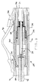
- FIGURE 5 Another preferred embodiment of the present invention is shown in FIGURE 5. This embodiment is used with fiber optic cable wherein the optical fibers 16, 18 are wrapped with a single strengthening element 20. To maintain proper loading,-the strengthening element 20 is affixed to the insert 44, as opposed to the plug pre-assemblies 40, 42.
- the insert 44 includes a rearwardly extending, substantially cylindrical boss 134.
- the boss 134 is centrally located, substantially interposed the first and second insert passageways 112, 114, and defines two, substantially opposed fiber slots 136, 138, extending therethrough.
- the fibers 16, 18 extend through the first and second insert passageways 112, 114 and the fiber slots 136, 138, terminated at the ferrules 92 in a conventional fashion.
- the fiber optic cable 12 is affixed to the plug 34 for proper loading, i.e., substantially avoiding strain on the optical fibers 16, 18.
- the housing 38 and the insert 44 cooperate to define interconnection means, generally designated 140, for (i) positioning and securing the plug pre-assemblies 40, 42 with respect to the plug 34, and (ii) structurally affixing or securing the strengthener 20 to the plug 34.
- the interconnection means 140 includes first crimp means, generally designated 142, for securing the single strengthening element 20 to the insert 44 or, more particularly, the boss 134 thereof.
- the interconnection means 140 includes second crimp means, generally designated 144, for securing the strengthening elements 22, 24 to the plug pre-assemblies 40, 42 or, more particularly, the backbones 98 thereof.
- the first and second crimp means 142, 144 include conventional fiber optic crimping elements 146.
- connection system 10 includes a conventional strain relief boot 148.
- the boot 148 is snap-locked to the insert 44, as best shown in FIGURES 2 and 5.
Landscapes
- Physics & Mathematics (AREA)
- General Physics & Mathematics (AREA)
- Optics & Photonics (AREA)
- Mechanical Coupling Of Light Guides (AREA)
Applications Claiming Priority (2)
| Application Number | Priority Date | Filing Date | Title |
|---|---|---|---|
| US499170 | 2000-02-04 | ||
| US09/499,170 US6511230B1 (en) | 2000-02-04 | 2000-02-04 | Fiber optic connection system |
Publications (3)
| Publication Number | Publication Date |
|---|---|
| EP1122566A2 true EP1122566A2 (fr) | 2001-08-08 |
| EP1122566A3 EP1122566A3 (fr) | 2003-11-19 |
| EP1122566B1 EP1122566B1 (fr) | 2005-07-27 |
Family
ID=23984127
Family Applications (1)
| Application Number | Title | Priority Date | Filing Date |
|---|---|---|---|
| EP01102320A Expired - Lifetime EP1122566B1 (fr) | 2000-02-04 | 2001-02-01 | Système de connexion pour fibre optique |
Country Status (5)
| Country | Link |
|---|---|
| US (2) | US6511230B1 (fr) |
| EP (1) | EP1122566B1 (fr) |
| JP (1) | JP2001264584A (fr) |
| CN (1) | CN1181365C (fr) |
| DE (1) | DE60112140T2 (fr) |
Cited By (21)
| Publication number | Priority date | Publication date | Assignee | Title |
|---|---|---|---|---|
| EP1296168A2 (fr) * | 2001-09-19 | 2003-03-26 | Fujitsu Quantum Devices Limited | Dispositif à fibre optique avec virole pour raccord optique |
| EP1889108A1 (fr) * | 2005-06-08 | 2008-02-20 | CommScope, Inc. of North Carolina | Cables de fibre optique et procedes pour former ceux-ci |
| WO2008123924A2 (fr) * | 2007-04-06 | 2008-10-16 | Westek Electronics, Inc. | Ensemble prise et capuchon anti-accrochage |
| DE102007033246A1 (de) * | 2007-07-17 | 2009-01-22 | Euromicron Werkzeuge Gmbh | Stecker zum Abschließen optischer Übertragungsmedien |
| EP2053699A1 (fr) * | 2007-10-27 | 2009-04-29 | LEONI Bordnetz-Systeme GmbH | Câble de signalisation et élément de contact pour un câble de signalisation |
| EP2206458A1 (fr) * | 2009-01-09 | 2010-07-14 | Tyco Healthcare Group LP | Prise et structure de connexion pour endoscope muni de celle-ci |
| EP2453271A1 (fr) * | 2009-08-05 | 2012-05-16 | Huawei Technologies Co., Ltd. | Connecteur de fibre optique à âme double du type mini |
| WO2014099840A1 (fr) * | 2012-12-21 | 2014-06-26 | 3M Innovative Properties Company | Connecteur électrique |
| EP2762935A3 (fr) * | 2001-09-28 | 2014-10-01 | Corning Cable Systems LLC | Connecteur à fibre optique et douille |
| US8979569B2 (en) | 2013-03-15 | 2015-03-17 | Ortronics, Inc. | Modular connectors and associated systems and methods |
| US8992098B2 (en) | 2005-06-08 | 2015-03-31 | Commscope, Inc. Of North Carolina | Methods for forming connectorized fiber optic cabling |
| US10359577B2 (en) | 2017-06-28 | 2019-07-23 | Corning Research & Development Corporation | Multiports and optical connectors with rotationally discrete locking and keying features |
| US10379298B2 (en) | 2017-06-28 | 2019-08-13 | Corning Research & Development Corporation | Fiber optic connectors and multiport assemblies including retention features |
| US10578812B2 (en) | 2005-06-08 | 2020-03-03 | Commscope, Inc. Of North Carolina | Methods for forming connectorized fiber optic cabling |
| US11294133B2 (en) | 2019-07-31 | 2022-04-05 | Corning Research & Development Corporation | Fiber optic networks using multiports and cable assemblies with cable-to-connector orientation |
| US11536921B2 (en) | 2020-02-11 | 2022-12-27 | Corning Research & Development Corporation | Fiber optic terminals having one or more loopback assemblies |
| US11604320B2 (en) | 2020-09-30 | 2023-03-14 | Corning Research & Development Corporation | Connector assemblies for telecommunication enclosures |
| US11686913B2 (en) | 2020-11-30 | 2023-06-27 | Corning Research & Development Corporation | Fiber optic cable assemblies and connector assemblies having a crimp ring and crimp body and methods of fabricating the same |
| US11880076B2 (en) | 2020-11-30 | 2024-01-23 | Corning Research & Development Corporation | Fiber optic adapter assemblies including a conversion housing and a release housing |
| US11927810B2 (en) | 2020-11-30 | 2024-03-12 | Corning Research & Development Corporation | Fiber optic adapter assemblies including a conversion housing and a release member |
| US11994722B2 (en) | 2021-11-09 | 2024-05-28 | Corning Research & Development Corporation | Fiber optic adapter assemblies including an adapter housing and a locking housing |
Families Citing this family (53)
| Publication number | Priority date | Publication date | Assignee | Title |
|---|---|---|---|---|
| DE10019104C2 (de) * | 2000-04-18 | 2003-04-03 | Krone Gmbh | Duplexverbinder für Glasfasersteckverbinder |
| US9239441B2 (en) | 2000-05-26 | 2016-01-19 | Corning Cable Systems Llc | Fiber optic drop cables and preconnectorized assemblies having toning portions |
| US6681177B2 (en) * | 2001-01-30 | 2004-01-20 | Rajashri Joshi | Bowing coefficient representation of curvature of geographic features |
| US20020181893A1 (en) * | 2001-02-16 | 2002-12-05 | James White | Strain relief boot assembly for optical fibers |
| US6893165B2 (en) * | 2002-03-01 | 2005-05-17 | Fci Americas Technology, Inc. | Optic fiber connectors and coupling sleeve |
| US6672771B2 (en) * | 2002-03-19 | 2004-01-06 | 3M Innovative Properties Company | Device for aligning fiber optic connectors |
| US6870996B2 (en) * | 2002-09-19 | 2005-03-22 | 3M Innovative Properties Company | Optical fiber plug including fiber positioning holder |
| KR100570421B1 (ko) * | 2002-09-30 | 2006-04-11 | 주식회사 케이티 | 플라스틱 광 케이블용 커넥터 |
| US6796845B2 (en) * | 2003-01-09 | 2004-09-28 | International Business Machines Corporation | Modular connector anti-snag enhancement |
| JP3910950B2 (ja) * | 2003-09-01 | 2007-04-25 | ヒロセ電機株式会社 | 遮蔽機構を有する光コネクタ |
| US6962445B2 (en) | 2003-09-08 | 2005-11-08 | Adc Telecommunications, Inc. | Ruggedized fiber optic connection |
| DE10342908A1 (de) * | 2003-09-17 | 2005-04-28 | Krone Gmbh | Gehäuse für Glasfaser- Steckverbinder und Verfahren zum Verlegen von Glasfaserkabeln |
| CN1316273C (zh) * | 2003-09-22 | 2007-05-16 | 捷耀光通讯股份有限公司 | 一种光纤收发信模组的抽取结构 |
| US7128471B2 (en) * | 2004-05-06 | 2006-10-31 | Avago Technologies Fiber Ip (Singapore) Pte. Ltd. | Single-use fiber optic cable |
| US7146090B2 (en) * | 2004-06-17 | 2006-12-05 | Corning Cable Systems Llc | Fiber optic cable and plug assembly |
| US7234877B2 (en) * | 2004-10-27 | 2007-06-26 | Panduit Corp. | Fiber optic industrial connector |
| US20060115218A1 (en) * | 2004-11-29 | 2006-06-01 | Us Conec, Ltd. | Boot for an optical ferrule |
| DE102005002186A1 (de) * | 2005-01-17 | 2006-07-27 | CCS Technology, Inc., Wilmington | Optisches Kabel, Anordnung zur Verbindung einer Vielzahl von Lichtwellenleitern und Verfahren zur Herstellung eines optischen Kabels |
| US7460758B2 (en) * | 2005-06-03 | 2008-12-02 | Telect Inc. | Fiber management system |
| US7366391B2 (en) * | 2005-06-03 | 2008-04-29 | Telect Inc. | Hybrid wire-fiber management |
| US7254307B2 (en) * | 2005-06-03 | 2007-08-07 | Telect Inc. | Fiber breakout system |
| US7683270B2 (en) * | 2005-06-03 | 2010-03-23 | Telect Inc. | Telecommunications cabinet |
| US7537393B2 (en) * | 2005-06-08 | 2009-05-26 | Commscope, Inc. Of North Carolina | Connectorized fiber optic cabling and methods for forming the same |
| US7636507B2 (en) * | 2005-06-17 | 2009-12-22 | Adc Telecommunications, Inc. | Compact blind mateable optical splitter |
| JP4767154B2 (ja) * | 2006-11-15 | 2011-09-07 | 富士通株式会社 | 光コネクタの抜け止め解除補助装置およびプリント基板装置 |
| US7572065B2 (en) | 2007-01-24 | 2009-08-11 | Adc Telecommunications, Inc. | Hardened fiber optic connector |
| US7641398B2 (en) * | 2007-03-15 | 2010-01-05 | O'riorden Stephen | Single boot for duplex fiber optic connectors |
| US7458730B1 (en) * | 2007-05-17 | 2008-12-02 | Erh-Te Huang | Optical fiber connector assembly |
| JP4456142B2 (ja) * | 2007-09-06 | 2010-04-28 | 本多通信工業株式会社 | リテーナ付きモールドケース |
| US20090080849A1 (en) * | 2007-09-20 | 2009-03-26 | Tellabs Petaluma, Inc. | Blank plate for managing cables |
| US7744286B2 (en) | 2007-12-11 | 2010-06-29 | Adc Telecommunications, Inc. | Hardened fiber optic connection system with multiple configurations |
| US8360798B2 (en) | 2008-04-24 | 2013-01-29 | Fci | Connector |
| DE102008026457A1 (de) * | 2008-06-03 | 2009-12-10 | Karl Storz Gmbh & Co. Kg | Medizinisches Instrument |
| CN101639554B (zh) * | 2008-08-01 | 2011-10-12 | 瑞轩科技股份有限公司 | 光纤连接器与光纤连接器组 |
| CN202149946U (zh) * | 2009-01-16 | 2012-02-22 | 新峤网络设备(上海)有限公司 | 光纤接入终端和光纤接入终端的光纤接口保护盖 |
| US8152385B2 (en) * | 2009-02-27 | 2012-04-10 | Corning Cable Systems Llc | Duplex fiber optic assemblies suitable for polarity reversal and methods therefor |
| US7695198B1 (en) * | 2009-03-30 | 2010-04-13 | Tyco Electronics Corporation | Latch protection clip for a connector |
| WO2012075121A2 (fr) | 2010-11-30 | 2012-06-07 | Adc Telecommunications, Inc. | Connecteur lc et procédé d'assemblage |
| DE102011003686A1 (de) | 2011-02-07 | 2012-08-09 | Trumpf Laser- Und Systemtechnik Gmbh | Laserbearbeitungsvorrichtung |
| US8764308B2 (en) | 2011-06-06 | 2014-07-01 | Panduit Corp. | Duplex clip assembly for fiber optic connectors |
| US8727638B2 (en) * | 2011-12-21 | 2014-05-20 | Alliance Fiber Optic Products Co., Ltd. | Fiber channel-inter changeable fiber optic connector |
| CN104364686B (zh) * | 2012-02-07 | 2016-11-16 | 泰科电子瑞侃有限公司 | 用于连接器的线缆端接组件和方法 |
| JP6122291B2 (ja) * | 2012-08-10 | 2017-04-26 | 矢崎総業株式会社 | 光コネクタ及び光コネクタの組立方法 |
| EP2706635B1 (fr) * | 2012-09-05 | 2017-03-08 | Tyco Electronics Nederland B.V. | Capuchon d'extrémité, agencement et kit pour terminer un câble de transmission |
| US9146362B2 (en) | 2012-09-21 | 2015-09-29 | Adc Telecommunications, Inc. | Insertion and removal tool for a fiber optic ferrule alignment sleeve |
| CN104181646A (zh) * | 2013-05-23 | 2014-12-03 | 中航光电科技股份有限公司 | 方便维修的光纤连接器 |
| WO2014206976A1 (fr) | 2013-06-27 | 2014-12-31 | Tyco Electronics Raychem Bvba | Dispositif d'ancrage de câble à fibre optique à utiliser avec des connecteurs à fibre optique et ses procédés d'utilisation |
| JP2018518704A (ja) | 2015-05-15 | 2018-07-12 | エーディーシー テレコミュニケーションズ(シャンハイ)ディストリビューション カンパニー リミテッド | アラインメントスリーブアセンブリ及び光ファイバーアダプター |
| US10156683B2 (en) | 2016-04-11 | 2018-12-18 | Leviton Manufacturing Co., Inc. | Polarity identification for polarity reversing duplex unibody connectors |
| US9946035B2 (en) | 2016-04-11 | 2018-04-17 | Leviton Manufacturing Co., Inc. | Fiber optic connector |
| US11187859B2 (en) | 2017-06-28 | 2021-11-30 | Corning Research & Development Corporation | Fiber optic connectors and methods of making the same |
| US10935736B2 (en) | 2019-02-25 | 2021-03-02 | Leviton Manufacturing Co., Inc. | Rotary clip for duplex polarity change |
| US11415758B2 (en) * | 2019-08-29 | 2022-08-16 | Senko Advanced Components, Inc. | Fiber optic connector, subassembly and method of making |
Citations (4)
| Publication number | Priority date | Publication date | Assignee | Title |
|---|---|---|---|---|
| US5317663A (en) * | 1993-05-20 | 1994-05-31 | Adc Telecommunications, Inc. | One-piece SC adapter |
| US5671310A (en) * | 1995-11-16 | 1997-09-23 | Tai Jin Mold Mfg. Co., Ltd. | Optical fiber connector having an adjustable engaging extent |
| US5692080A (en) * | 1996-10-03 | 1997-11-25 | Adc Telecommunications, Inc. | Double ferrule SC connector and adapter |
| EP0949522A2 (fr) * | 1998-04-08 | 1999-10-13 | Molex Incorporated | Arrangement pour receptacle d'un connecteur à fibre optique |
Family Cites Families (14)
| Publication number | Priority date | Publication date | Assignee | Title |
|---|---|---|---|---|
| US4648688A (en) | 1982-05-24 | 1987-03-10 | Amp Incorporated | Connector for fiber optic member including polishing fixture and method of terminating same |
| JPS59204017A (ja) * | 1983-05-06 | 1984-11-19 | Sumitomo Electric Ind Ltd | 突出し防止用光コネクタ |
| US4762389A (en) | 1984-03-30 | 1988-08-09 | Nec Corporation | Optical fiber connector |
| US5076656A (en) | 1984-06-08 | 1991-12-31 | Briggs Robert C | High precision optical fiber connectors |
| US5157749A (en) | 1984-06-08 | 1992-10-20 | Amp Incorporated | High precision optical fiber connectors |
| US5259052A (en) | 1984-06-08 | 1993-11-02 | Amp Incorporated | High precision optical fiber connectors |
| US4744629A (en) | 1985-08-16 | 1988-05-17 | Augat Inc. | Multifiber optical cable connector |
| JPH077139B2 (ja) | 1985-12-24 | 1995-01-30 | 日本電信電話株式会社 | 浮動ホルダ型光コネクタ |
| US4787706A (en) | 1987-02-03 | 1988-11-29 | American Telephone And Telegraph Company, At&T Bell Laboratories | Duplex optical fiber connector |
| US5016968A (en) | 1989-09-27 | 1991-05-21 | At&T Bell Laboratories | Duplex optical fiber connector and cables terminated therewith |
| US5315679A (en) | 1992-04-27 | 1994-05-24 | International Business Machines Corporation | Optical fibers duplex connector assembly |
| US5311609A (en) | 1992-10-29 | 1994-05-10 | Hirose Electric Co., Ltd. | Optical fiber connector |
| JP3002399B2 (ja) | 1995-01-13 | 2000-01-24 | 株式会社精工技研 | 光ファイバ端面研磨機用の光ファイバフェルールホルダ |
| US5828804A (en) | 1996-10-15 | 1998-10-27 | Panduit Corp. | Fiber optic connector system |
-
2000
- 2000-02-04 US US09/499,170 patent/US6511230B1/en not_active Expired - Lifetime
-
2001
- 2001-01-30 JP JP2001021580A patent/JP2001264584A/ja active Pending
- 2001-02-01 EP EP01102320A patent/EP1122566B1/fr not_active Expired - Lifetime
- 2001-02-01 DE DE60112140T patent/DE60112140T2/de not_active Expired - Fee Related
- 2001-02-05 CN CNB011032464A patent/CN1181365C/zh not_active Expired - Fee Related
-
2002
- 2002-11-05 US US10/288,163 patent/US6575640B2/en not_active Expired - Lifetime
Patent Citations (4)
| Publication number | Priority date | Publication date | Assignee | Title |
|---|---|---|---|---|
| US5317663A (en) * | 1993-05-20 | 1994-05-31 | Adc Telecommunications, Inc. | One-piece SC adapter |
| US5671310A (en) * | 1995-11-16 | 1997-09-23 | Tai Jin Mold Mfg. Co., Ltd. | Optical fiber connector having an adjustable engaging extent |
| US5692080A (en) * | 1996-10-03 | 1997-11-25 | Adc Telecommunications, Inc. | Double ferrule SC connector and adapter |
| EP0949522A2 (fr) * | 1998-04-08 | 1999-10-13 | Molex Incorporated | Arrangement pour receptacle d'un connecteur à fibre optique |
Cited By (53)
| Publication number | Priority date | Publication date | Assignee | Title |
|---|---|---|---|---|
| EP1296168A3 (fr) * | 2001-09-19 | 2005-01-12 | Fujitsu Quantum Devices Limited | Dispositif à fibre optique avec virole pour raccord optique |
| US7144164B2 (en) | 2001-09-19 | 2006-12-05 | Fujitsu Quantum Devices Limited | Optical device and method of manufacturing the same |
| EP1296168A2 (fr) * | 2001-09-19 | 2003-03-26 | Fujitsu Quantum Devices Limited | Dispositif à fibre optique avec virole pour raccord optique |
| EP2983025A3 (fr) * | 2001-09-28 | 2016-04-20 | Corning Optical Communications LLC | Assemblage de connecteur à fibre optique et réceptacle |
| EP2772778B1 (fr) | 2001-09-28 | 2016-01-06 | Corning Optical Communications LLC | Connecteur à fibre optique |
| EP2293128B1 (fr) * | 2001-09-28 | 2016-11-09 | Corning Optical Communications LLC | Connecteur à fibre optique |
| EP2772778A3 (fr) * | 2001-09-28 | 2014-11-05 | Corning Optical Communications LLC | Connecteur à fibre optique |
| EP2762935A3 (fr) * | 2001-09-28 | 2014-10-01 | Corning Cable Systems LLC | Connecteur à fibre optique et douille |
| EP2772778B2 (fr) † | 2001-09-28 | 2020-08-26 | Corning Optical Communications LLC | Connecteur à fibre optique |
| US11474309B2 (en) | 2005-06-08 | 2022-10-18 | Commscope, Inc. Of North Carolina | Connectorized fiber optic cabling assembly |
| US11112568B2 (en) | 2005-06-08 | 2021-09-07 | Commscope, Inc. Of North Carolina | Connectorized fiber optic cabling assembly |
| US10859773B2 (en) | 2005-06-08 | 2020-12-08 | Commscope, Inc. Of North Carolina | Methods for forming connectorized fiber optic cabling |
| US10302878B2 (en) | 2005-06-08 | 2019-05-28 | Commscope, Inc. Of North Carolina | Methods for forming connectorized fiber optic cabling |
| US10012805B2 (en) | 2005-06-08 | 2018-07-03 | Commscope, Inc. Of North Carolina | Methods for forming connectorized fiber optic cabling |
| US9690057B2 (en) | 2005-06-08 | 2017-06-27 | Commscope, Inc. Of North Carolina | Methods for forming connectorized fiber optic cabling |
| US10578812B2 (en) | 2005-06-08 | 2020-03-03 | Commscope, Inc. Of North Carolina | Methods for forming connectorized fiber optic cabling |
| US8992098B2 (en) | 2005-06-08 | 2015-03-31 | Commscope, Inc. Of North Carolina | Methods for forming connectorized fiber optic cabling |
| US9229174B2 (en) | 2005-06-08 | 2016-01-05 | Commscope, Inc. Of North Carolina | Methods for forming connnectorized fiber optic cabling |
| EP1889108A1 (fr) * | 2005-06-08 | 2008-02-20 | CommScope, Inc. of North Carolina | Cables de fibre optique et procedes pour former ceux-ci |
| WO2008123924A3 (fr) * | 2007-04-06 | 2009-01-15 | Westek Electronics Inc | Ensemble prise et capuchon anti-accrochage |
| WO2008123924A2 (fr) * | 2007-04-06 | 2008-10-16 | Westek Electronics, Inc. | Ensemble prise et capuchon anti-accrochage |
| WO2009010210A1 (fr) | 2007-07-17 | 2009-01-22 | Euromicron Werkreuge Gmbh | Fiche de fermeture de supports optiques de transfert |
| US8061906B2 (en) | 2007-07-17 | 2011-11-22 | Euromicron Werkzeuge Gmbh | Fibre optic duplex connector |
| DE102007033246A1 (de) * | 2007-07-17 | 2009-01-22 | Euromicron Werkzeuge Gmbh | Stecker zum Abschließen optischer Übertragungsmedien |
| EP2053699A1 (fr) * | 2007-10-27 | 2009-04-29 | LEONI Bordnetz-Systeme GmbH | Câble de signalisation et élément de contact pour un câble de signalisation |
| US8348524B2 (en) | 2009-01-09 | 2013-01-08 | Covidien Lp | Plug and connecting structure for endoscope |
| EP2206458A1 (fr) * | 2009-01-09 | 2010-07-14 | Tyco Healthcare Group LP | Prise et structure de connexion pour endoscope muni de celle-ci |
| EP2453271A4 (fr) * | 2009-08-05 | 2012-06-13 | Huawei Tech Co Ltd | Connecteur de fibre optique à âme double du type mini |
| EP2453271A1 (fr) * | 2009-08-05 | 2012-05-16 | Huawei Technologies Co., Ltd. | Connecteur de fibre optique à âme double du type mini |
| WO2014099840A1 (fr) * | 2012-12-21 | 2014-06-26 | 3M Innovative Properties Company | Connecteur électrique |
| US8979569B2 (en) | 2013-03-15 | 2015-03-17 | Ortronics, Inc. | Modular connectors and associated systems and methods |
| US10359577B2 (en) | 2017-06-28 | 2019-07-23 | Corning Research & Development Corporation | Multiports and optical connectors with rotationally discrete locking and keying features |
| US11536913B2 (en) | 2017-06-28 | 2022-12-27 | Corning Research & Development Corporation | Fiber optic connectors and connectorization employing adhesive admitting adapters |
| US10386584B2 (en) | 2017-06-28 | 2019-08-20 | Corning Research & Development Corporation | Optical connectors with locking and keying features for interfacing with multiports |
| US11906792B2 (en) | 2017-06-28 | 2024-02-20 | Corning Research & Development Corporation | Compact fiber optic connectors having multiple connector footprints, along with cable assemblies and methods of making the same |
| US11460646B2 (en) | 2017-06-28 | 2022-10-04 | Corning Research & Development Corporation | Fiber optic connectors and multiport assemblies including retention features |
| US10379298B2 (en) | 2017-06-28 | 2019-08-13 | Corning Research & Development Corporation | Fiber optic connectors and multiport assemblies including retention features |
| US10429593B2 (en) | 2017-06-28 | 2019-10-01 | Corning Research & Development Corporation | Fiber optic connectors and connectorization employing adapter extensions and/or flexures |
| US11914197B2 (en) | 2017-06-28 | 2024-02-27 | Corning Research & Development Corporation | Compact fiber optic connectors having multiple connector footprints, along with cable assemblies and methods of making the same |
| US11543600B2 (en) | 2017-06-28 | 2023-01-03 | Corning Research & Development Corporation | Compact fiber optic connectors having multiple connector footprints, along with cable assemblies and methods of making the same |
| US11579377B2 (en) | 2017-06-28 | 2023-02-14 | Corning Research & Development Corporation | Compact fiber optic connectors, cable assemblies and methods of making the same with alignment elements |
| US11966089B2 (en) | 2017-06-28 | 2024-04-23 | Corning Optical Communications, Llc | Multiports having connection ports formed in the shell and associated securing features |
| US11940656B2 (en) | 2017-06-28 | 2024-03-26 | Corning Research & Development Corporation | Compact fiber optic connectors, cable assemblies and methods of making the same |
| US11703646B2 (en) | 2017-06-28 | 2023-07-18 | Corning Research & Development Corporation | Multiports and optical connectors with rotationally discrete locking and keying features |
| US11914198B2 (en) | 2017-06-28 | 2024-02-27 | Corning Research & Development Corporation | Compact fiber optic connectors having multiple connector footprints, along with cable assemblies and methods of making the same |
| US11886017B2 (en) | 2017-06-28 | 2024-01-30 | Corning Research & Development Corporation | Multiports and other devices having connection ports with securing features and methods of making the same |
| US11294133B2 (en) | 2019-07-31 | 2022-04-05 | Corning Research & Development Corporation | Fiber optic networks using multiports and cable assemblies with cable-to-connector orientation |
| US11536921B2 (en) | 2020-02-11 | 2022-12-27 | Corning Research & Development Corporation | Fiber optic terminals having one or more loopback assemblies |
| US11604320B2 (en) | 2020-09-30 | 2023-03-14 | Corning Research & Development Corporation | Connector assemblies for telecommunication enclosures |
| US11880076B2 (en) | 2020-11-30 | 2024-01-23 | Corning Research & Development Corporation | Fiber optic adapter assemblies including a conversion housing and a release housing |
| US11927810B2 (en) | 2020-11-30 | 2024-03-12 | Corning Research & Development Corporation | Fiber optic adapter assemblies including a conversion housing and a release member |
| US11686913B2 (en) | 2020-11-30 | 2023-06-27 | Corning Research & Development Corporation | Fiber optic cable assemblies and connector assemblies having a crimp ring and crimp body and methods of fabricating the same |
| US11994722B2 (en) | 2021-11-09 | 2024-05-28 | Corning Research & Development Corporation | Fiber optic adapter assemblies including an adapter housing and a locking housing |
Also Published As
| Publication number | Publication date |
|---|---|
| US20030059168A1 (en) | 2003-03-27 |
| DE60112140T2 (de) | 2006-06-08 |
| JP2001264584A (ja) | 2001-09-26 |
| DE60112140D1 (de) | 2005-09-01 |
| EP1122566B1 (fr) | 2005-07-27 |
| US6511230B1 (en) | 2003-01-28 |
| CN1181365C (zh) | 2004-12-22 |
| US6575640B2 (en) | 2003-06-10 |
| CN1311448A (zh) | 2001-09-05 |
| EP1122566A3 (fr) | 2003-11-19 |
Similar Documents
| Publication | Publication Date | Title |
|---|---|---|
| US6511230B1 (en) | Fiber optic connection system | |
| US5748821A (en) | Adapter assembly for fiber optic connectors | |
| US6347888B1 (en) | Fiber optic adapter, including hybrid connector system | |
| EP0758099B1 (fr) | Assemblage avec adaptateur pour connecteurs à fibres optiques | |
| US5317663A (en) | One-piece SC adapter | |
| US6634796B2 (en) | Polarity reversal for fiber optic connections | |
| US7500790B2 (en) | Connector assembly clip | |
| US11914195B2 (en) | Fiber optic ferrule and fiber optic ferrule receiver | |
| EP1148364A2 (fr) | Dispositif serre-câble pour soulagement de traction pour connecteur à fibre optique | |
| US11966088B2 (en) | Optical fiber connectors | |
| US20230244041A1 (en) | Telecommunications connector with latch release mechanism | |
| US6206580B1 (en) | Optical connector | |
| US6485195B2 (en) | Ferrule and fiber optic connector housing having enlarged shoulders | |
| US20210223485A1 (en) | Optical fiber connectors | |
| EP3707541B1 (fr) | Protecteur pour connecteur optique sc | |
| JP2573482Y2 (ja) | 2心光コネクタ | |
| US20050058401A1 (en) | Keyed adapter and connector | |
| WO2021144650A1 (fr) | Câbles de dérivation à fibres multiples pré-équipés de connecteurs et procédés de déploiement et d'assemblage de câbles de dérivation à fibres multiples pré-équipés de connecteurs | |
| MXPA01005125A (es) | Adaptador de fibra optica, incluyendo un sistema conector hibrido |
Legal Events
| Date | Code | Title | Description |
|---|---|---|---|
| PUAI | Public reference made under article 153(3) epc to a published international application that has entered the european phase |
Free format text: ORIGINAL CODE: 0009012 |
|
| AK | Designated contracting states |
Kind code of ref document: A2 Designated state(s): AT BE CH CY DE DK ES FI FR GB GR IE IT LI LU MC NL PT SE TR |
|
| AX | Request for extension of the european patent |
Free format text: AL;LT;LV;MK;RO;SI |
|
| PUAL | Search report despatched |
Free format text: ORIGINAL CODE: 0009013 |
|
| AK | Designated contracting states |
Kind code of ref document: A3 Designated state(s): AT BE CH CY DE DK ES FI FR GB GR IE IT LI LU MC NL PT SE TR |
|
| AX | Request for extension of the european patent |
Extension state: AL LT LV MK RO SI |
|
| 17P | Request for examination filed |
Effective date: 20040119 |
|
| 17Q | First examination report despatched |
Effective date: 20040226 |
|
| AKX | Designation fees paid |
Designated state(s): DE FR GB IT |
|
| GRAP | Despatch of communication of intention to grant a patent |
Free format text: ORIGINAL CODE: EPIDOSNIGR1 |
|
| GRAS | Grant fee paid |
Free format text: ORIGINAL CODE: EPIDOSNIGR3 |
|
| GRAA | (expected) grant |
Free format text: ORIGINAL CODE: 0009210 |
|
| AK | Designated contracting states |
Kind code of ref document: B1 Designated state(s): DE FR GB IT |
|
| REG | Reference to a national code |
Ref country code: GB Ref legal event code: FG4D |
|
| REF | Corresponds to: |
Ref document number: 60112140 Country of ref document: DE Date of ref document: 20050901 Kind code of ref document: P |
|
| ET | Fr: translation filed | ||
| PLBE | No opposition filed within time limit |
Free format text: ORIGINAL CODE: 0009261 |
|
| STAA | Information on the status of an ep patent application or granted ep patent |
Free format text: STATUS: NO OPPOSITION FILED WITHIN TIME LIMIT |
|
| 26N | No opposition filed |
Effective date: 20060428 |
|
| PGFP | Annual fee paid to national office [announced via postgrant information from national office to epo] |
Ref country code: DE Payment date: 20080124 Year of fee payment: 8 Ref country code: IT Payment date: 20080227 Year of fee payment: 8 |
|
| PGFP | Annual fee paid to national office [announced via postgrant information from national office to epo] |
Ref country code: FR Payment date: 20080208 Year of fee payment: 8 |
|
| REG | Reference to a national code |
Ref country code: FR Ref legal event code: ST Effective date: 20091030 |
|
| PG25 | Lapsed in a contracting state [announced via postgrant information from national office to epo] |
Ref country code: DE Free format text: LAPSE BECAUSE OF NON-PAYMENT OF DUE FEES Effective date: 20090901 |
|
| PG25 | Lapsed in a contracting state [announced via postgrant information from national office to epo] |
Ref country code: FR Free format text: LAPSE BECAUSE OF NON-PAYMENT OF DUE FEES Effective date: 20090302 |
|
| PG25 | Lapsed in a contracting state [announced via postgrant information from national office to epo] |
Ref country code: IT Free format text: LAPSE BECAUSE OF NON-PAYMENT OF DUE FEES Effective date: 20090201 |
|
| PGFP | Annual fee paid to national office [announced via postgrant information from national office to epo] |
Ref country code: GB Payment date: 20140227 Year of fee payment: 14 |
|
| GBPC | Gb: european patent ceased through non-payment of renewal fee |
Effective date: 20150201 |
|
| PG25 | Lapsed in a contracting state [announced via postgrant information from national office to epo] |
Ref country code: GB Free format text: LAPSE BECAUSE OF NON-PAYMENT OF DUE FEES Effective date: 20150201 |