US5311609A - Optical fiber connector - Google Patents
Optical fiber connector Download PDFInfo
- Publication number
- US5311609A US5311609A US07/968,330 US96833092A US5311609A US 5311609 A US5311609 A US 5311609A US 96833092 A US96833092 A US 96833092A US 5311609 A US5311609 A US 5311609A
- Authority
- US
- United States
- Prior art keywords
- ferrule
- optical fiber
- stopper plate
- conical spring
- receiving cavity
- Prior art date
- Legal status (The legal status is an assumption and is not a legal conclusion. Google has not performed a legal analysis and makes no representation as to the accuracy of the status listed.)
- Expired - Fee Related
Links
Images


Classifications
-
- G—PHYSICS
- G02—OPTICS
- G02B—OPTICAL ELEMENTS, SYSTEMS OR APPARATUS
- G02B6/00—Light guides; Structural details of arrangements comprising light guides and other optical elements, e.g. couplings
- G02B6/24—Coupling light guides
- G02B6/36—Mechanical coupling means
- G02B6/38—Mechanical coupling means having fibre to fibre mating means
- G02B6/3807—Dismountable connectors, i.e. comprising plugs
- G02B6/381—Dismountable connectors, i.e. comprising plugs of the ferrule type, e.g. fibre ends embedded in ferrules, connecting a pair of fibres
- G02B6/3818—Dismountable connectors, i.e. comprising plugs of the ferrule type, e.g. fibre ends embedded in ferrules, connecting a pair of fibres of a low-reflection-loss type
- G02B6/3821—Dismountable connectors, i.e. comprising plugs of the ferrule type, e.g. fibre ends embedded in ferrules, connecting a pair of fibres of a low-reflection-loss type with axial spring biasing or loading means
-
- G—PHYSICS
- G02—OPTICS
- G02B—OPTICAL ELEMENTS, SYSTEMS OR APPARATUS
- G02B6/00—Light guides; Structural details of arrangements comprising light guides and other optical elements, e.g. couplings
- G02B6/24—Coupling light guides
- G02B6/36—Mechanical coupling means
- G02B6/38—Mechanical coupling means having fibre to fibre mating means
- G02B6/3807—Dismountable connectors, i.e. comprising plugs
- G02B6/3869—Mounting ferrules to connector body, i.e. plugs
-
- G—PHYSICS
- G02—OPTICS
- G02B—OPTICAL ELEMENTS, SYSTEMS OR APPARATUS
- G02B6/00—Light guides; Structural details of arrangements comprising light guides and other optical elements, e.g. couplings
- G02B6/24—Coupling light guides
- G02B6/36—Mechanical coupling means
- G02B6/38—Mechanical coupling means having fibre to fibre mating means
- G02B6/3807—Dismountable connectors, i.e. comprising plugs
- G02B6/3873—Connectors using guide surfaces for aligning ferrule ends, e.g. tubes, sleeves, V-grooves, rods, pins, balls
- G02B6/3874—Connectors using guide surfaces for aligning ferrule ends, e.g. tubes, sleeves, V-grooves, rods, pins, balls using tubes, sleeves to align ferrules
- G02B6/3878—Connectors using guide surfaces for aligning ferrule ends, e.g. tubes, sleeves, V-grooves, rods, pins, balls using tubes, sleeves to align ferrules comprising a plurality of ferrules, branching and break-out means
Definitions
- the present invention relates to optical fiber connectors.
- FIG. 12 shows an optical fiber connector.
- a ferrule 21 is held by a ferrule holder 22 which is housed in the receiving cavity 3 of a connector case 1 such that its bosses 23 and 24 are housed in channels 4 and 5 of the connector case 1 respectively.
- FIG. 13 shows another optical fiber connector.
- a connector case 1 is provided at the rear end with a cable receiving aperture 2, into which an optical fiber cable 11 is inserted and secured to the connector case 1 by a threaded nut 12.
- An optical fiber 13 extends forwardly from the end of the cable 11 and terminates at a ferrule holder 22 which holds a ferrule 21 at the front end.
- the connector case 1 is provided at the front end with a receiving cavity 3 for housing the ferrule holder 22.
- the ferrule 21 extends forwardly in a front opening 8 of the connector case 1.
- a pair of arms 9 extends rearwardly from opposite sides of the connector case 1 for engagement with a mating plug.
- the ferrule 21 is held by the ferrule holder 22 which is housed in the receiving cavity 3.
- the ferrule holder 22 is provided at the front end with a conical boss 25 with a flange 26 and at the rear end with a rear front flange 27 which abuts on an end clip 29.
- a coil spring 28 is placed between the flanges 26 and 27 for biasing the conical boss 25 forwardly so that the corner portion 25a abuts on the aperture 7 of the connector case 1 while the flanges 26 and 27 abut on the inside walls 3b and 3a of the receiving cavity 3, respectively.
- the gap between the ferrule holder 22 and the receiving cavity 3 is so small that when the ferrule 21 is fitted into a precision sleeve 30, a small radial offset between the ferrule and the precision sleeve 30 causes a collision between them.
- the ferrule 21 is pushed rearwardly so that the rear end 22a of the ferrule holder 22 is pushed against the end wall 22a of the receiving cavity 3, producing a friction resistance in proportion to the pushing force.
- This friction resistance restricts the radial movement of the ferrule 21, making it very difficult to fit the ferrule 21 into the precision sleeve 30.
- the corner portion 25a of the conical boss 25 abuts on the aperture 7 of the connector case 1 with little or no play so that even when the ferrule 21 is pushed rearwardly upon fitting into the precision sleeve 30, it hardly moves in the radial direction, making it very difficult to fit the ferrule 21 into the precision sleeve 30.
- an object of the invention to provide an optical fiber connector with a ferrule movable in the radial direction to such an extent that it is easy to fit the ferrule into a precision sleeve.
- an optical fiber connector which includes a connector case having a receiving cavity; a ferrule; a ferrule holder movable within the receiving cavity and holding the ferrule at its front end; and a conical spring for biasing the ferrule holder forwardly so that the ferrule projects forwardly from the receiving cavity.
- the ferrule If the ferrule is not axial agreement with the mating sleeve, it is pushed rearwardly by the mating sleeve against the biasing of the conical spring so that the front flange of the ferrule holder leaves from the transverse rib of the case, thereby permitting large radial movement of the ferrule, making it easy to fitting the ferrule into the precision sleeve.
- FIG. 1 is a partially sectional, side elevational view of an optical fiber connector according to an embodiment of the invention
- FIG. 2 is a side elevational view of a connector housing for the optical fiber connector
- FIG. 3 is a side elevational view of a cover plate for the optical fiber connector
- FIG. 4 is a partially sectional, side elevational view of a ferrule holder assembly for the optical fiber connector
- FIG. 5 is a partially sectional, side elevational view of a ferrule holder for the ferrule holder assembly
- FIG. 6 is a front elevational view of the ferrule holder
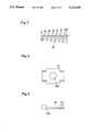
- FIG. 7 is a partially sectional, side elevational view of a conical spring for the ferrule holder assembly
- FIG. 8 is a front elevational view of a stopper plate for the optical fiber connector
- FIG. 9 is a partially sectional, top plan view of the stopper plate
- FIGS. 10 and 11 show how the optical fiber connector works
- FIG. 12 shows an optical fiber connector prior to the present invention
- FIG. 13 is a side elevational view of another optical fiber connector prior to the present invention.
- FIG. 14 shows how the other optical fiber connector works.
- a connector case 1 is provided at the rear end with an insertion aperture 14 into which a rubber hood 11 is inserted.
- An optical fiber cable 15 is inserted into the rubber hood 15 and secured by a fastening member 15a.
- An optical fiber 13 extends forwardly from the end of the cable 11 and terminates at a ferrule holder assembly 20 which holds a ferrule 21 at the front end.
- the connector case 1 has an opening mouth 8 at the front portion and the insertion aperture 14 at the rear portion.
- a pair of arms 9 with a projection 9a extend rearwardly from opposite sides of the case 1.
- a pair of transverse ribs 16 and 17 are formed in the front portion of the case 1, defining a receiving cavity 3 between them.
- Semi-circular cuts 18 and 19 are formed on the transverse ribs 16 and 17, respectively, communicating with the receiving cavity 3.
- the diameter of the semi-circular cut 18 is made larger than that of the front boss 33 of a ferrule holder 31 hereinafter described.
- the notch 10a of a cover plate 10 receives a protrusion 1a of the connector case 1 to secure the cover plate 10 to the connector case 1.
- a ferrule 21 is held by a ferrule holder 31 of the ferrule holder assembly 20.
- a conical spring 38 is placed between a front flange 32 of the ferrule holder 31 and a stop plate 37 abutting on the stop ring 36 which is secured to the rear end of the ferrule holder 31.
- the boss 33 of the ferrule holder 31 has a ferrule receiving hole 33a.
- a square flange 32 has a rear face 32b on which the conical spring 38 abuts.
- the square flange 32 prevents the ferrule holder 31 from rotation, and the front face 32 of the square flange 32 abuts on the transverse rib 16 under the biasing of the conical spring 38.
- a rear flange 34 is formed on the rear end portion of the ferrule holder 31.
- the stop ring 36 is secured to the front face 34a of the flange 34.
- the stopper plate 37 is movable along a boss 35 and biased by the conical spring 38 against the stop ring 36.
- the stopper plate 37 has four bent members 37c at the corners to prevent the conical spring 38 from being offset.
- An aperture 37b having a diameter greater than that of the boss 35 is formed at the center of the stopper plate 37.
- the ferrule holder assembly 20 is housed in the receiving cavity 3 of the connector case 1 such that the front face 32a of the flange 32 and the rear face 37a of the stopper plate 37 are biased by the conical spring 38 against the transverse ribs 16 and 17, respectively.
Landscapes
- Physics & Mathematics (AREA)
- General Physics & Mathematics (AREA)
- Optics & Photonics (AREA)
- Mechanical Coupling Of Light Guides (AREA)
Abstract
Description
Claims (2)
Priority Applications (1)
| Application Number | Priority Date | Filing Date | Title |
|---|---|---|---|
| US07/968,330 US5311609A (en) | 1992-10-29 | 1992-10-29 | Optical fiber connector |
Applications Claiming Priority (1)
| Application Number | Priority Date | Filing Date | Title |
|---|---|---|---|
| US07/968,330 US5311609A (en) | 1992-10-29 | 1992-10-29 | Optical fiber connector |
Publications (1)
| Publication Number | Publication Date |
|---|---|
| US5311609A true US5311609A (en) | 1994-05-10 |
Family
ID=25514091
Family Applications (1)
| Application Number | Title | Priority Date | Filing Date |
|---|---|---|---|
| US07/968,330 Expired - Fee Related US5311609A (en) | 1992-10-29 | 1992-10-29 | Optical fiber connector |
Country Status (1)
| Country | Link |
|---|---|
| US (1) | US5311609A (en) |
Cited By (12)
| Publication number | Priority date | Publication date | Assignee | Title |
|---|---|---|---|---|
| US5428703A (en) * | 1994-02-18 | 1995-06-27 | Augat Inc. | One-piece SC fiber optic connector |
| US5436995A (en) * | 1993-05-14 | 1995-07-25 | Nippon Telegraph And Telephone Corporation | Optical fiber connector unit and optical fiber connector |
| US5485537A (en) * | 1994-09-10 | 1996-01-16 | Electronics And Telecommunications Research Institute | Single core optical fiber connector |
| WO1997009647A2 (en) * | 1995-09-01 | 1997-03-13 | Siemens Aktiengesellschaft | Optical plug connector |
| US5915057A (en) * | 1995-09-01 | 1999-06-22 | Siemens Aktiengesellschaft | Connector for a fiber optic cable |
| US5953475A (en) * | 1995-09-01 | 1999-09-14 | Siemens Aktiengesellschaft | Fiber optic plug connector |
| US6076974A (en) * | 1998-09-14 | 2000-06-20 | Lucent Technologies Inc. | Optical fiber connector |
| US6254283B1 (en) | 2000-02-22 | 2001-07-03 | Itt Manufacturing Enterprises, Inc. | Terminus body retention |
| US6398423B1 (en) | 1999-12-15 | 2002-06-04 | Itt Manufacturing Enterprises, Inc. | Optic fiber retaining system |
| US6435730B1 (en) | 1998-05-06 | 2002-08-20 | The Whitaker Corporation | Optical fiber connector with improved ferrule float feature |
| US6511230B1 (en) | 2000-02-04 | 2003-01-28 | Panduit Corp. | Fiber optic connection system |
| WO2006032153A1 (en) * | 2004-09-24 | 2006-03-30 | Reichle & De-Massari Ag | Inner housing for a fibre-optic plug connector |
Citations (5)
| Publication number | Priority date | Publication date | Assignee | Title |
|---|---|---|---|---|
| US4516829A (en) * | 1982-05-12 | 1985-05-14 | International Telephone & Telegraph Corporation | Fiber optic contact retention assembly |
| US4518220A (en) * | 1983-03-30 | 1985-05-21 | Gte Products Corporation | Fiber optic drawer connector assembly |
| US4805978A (en) * | 1986-07-29 | 1989-02-21 | Siemens Aktiengesellschaft | Device having a light waveguide plug connector |
| US5016968A (en) * | 1989-09-27 | 1991-05-21 | At&T Bell Laboratories | Duplex optical fiber connector and cables terminated therewith |
| US5157749A (en) * | 1984-06-08 | 1992-10-20 | Amp Incorporated | High precision optical fiber connectors |
-
1992
- 1992-10-29 US US07/968,330 patent/US5311609A/en not_active Expired - Fee Related
Patent Citations (5)
| Publication number | Priority date | Publication date | Assignee | Title |
|---|---|---|---|---|
| US4516829A (en) * | 1982-05-12 | 1985-05-14 | International Telephone & Telegraph Corporation | Fiber optic contact retention assembly |
| US4518220A (en) * | 1983-03-30 | 1985-05-21 | Gte Products Corporation | Fiber optic drawer connector assembly |
| US5157749A (en) * | 1984-06-08 | 1992-10-20 | Amp Incorporated | High precision optical fiber connectors |
| US4805978A (en) * | 1986-07-29 | 1989-02-21 | Siemens Aktiengesellschaft | Device having a light waveguide plug connector |
| US5016968A (en) * | 1989-09-27 | 1991-05-21 | At&T Bell Laboratories | Duplex optical fiber connector and cables terminated therewith |
Cited By (16)
| Publication number | Priority date | Publication date | Assignee | Title |
|---|---|---|---|---|
| US5436995A (en) * | 1993-05-14 | 1995-07-25 | Nippon Telegraph And Telephone Corporation | Optical fiber connector unit and optical fiber connector |
| US5428703A (en) * | 1994-02-18 | 1995-06-27 | Augat Inc. | One-piece SC fiber optic connector |
| WO1995022775A1 (en) * | 1994-02-18 | 1995-08-24 | Augat Inc. | One-piece sc fiber optic connector |
| US5515466A (en) * | 1994-02-18 | 1996-05-07 | Augat Inc. | One-piece SC fiber optic connector and method of terminating optical fiber using same |
| US5485537A (en) * | 1994-09-10 | 1996-01-16 | Electronics And Telecommunications Research Institute | Single core optical fiber connector |
| US5953475A (en) * | 1995-09-01 | 1999-09-14 | Siemens Aktiengesellschaft | Fiber optic plug connector |
| WO1997009647A3 (en) * | 1995-09-01 | 1997-05-09 | Siemens Ag | Optical plug connector |
| US5915057A (en) * | 1995-09-01 | 1999-06-22 | Siemens Aktiengesellschaft | Connector for a fiber optic cable |
| WO1997009647A2 (en) * | 1995-09-01 | 1997-03-13 | Siemens Aktiengesellschaft | Optical plug connector |
| US6435730B1 (en) | 1998-05-06 | 2002-08-20 | The Whitaker Corporation | Optical fiber connector with improved ferrule float feature |
| US6076974A (en) * | 1998-09-14 | 2000-06-20 | Lucent Technologies Inc. | Optical fiber connector |
| US6398423B1 (en) | 1999-12-15 | 2002-06-04 | Itt Manufacturing Enterprises, Inc. | Optic fiber retaining system |
| US6511230B1 (en) | 2000-02-04 | 2003-01-28 | Panduit Corp. | Fiber optic connection system |
| US6254283B1 (en) | 2000-02-22 | 2001-07-03 | Itt Manufacturing Enterprises, Inc. | Terminus body retention |
| WO2006032153A1 (en) * | 2004-09-24 | 2006-03-30 | Reichle & De-Massari Ag | Inner housing for a fibre-optic plug connector |
| US20070211998A1 (en) * | 2004-09-24 | 2007-09-13 | Marion Muhlegg | Inner Housing For A Fibre-Optic Plug Connector |
Similar Documents
| Publication | Publication Date | Title |
|---|---|---|
| US5311609A (en) | Optical fiber connector | |
| US4838641A (en) | Optical fiber connector | |
| EP0475415B1 (en) | Multiple pole electrical connector | |
| US20070047877A1 (en) | Duplex style fiber optic connector interface assembly | |
| US4359254A (en) | Electrical connector coupling ring having an integral spring | |
| US4747656A (en) | Optical fiber connector with locking mechanism | |
| US5751874A (en) | Coupling device for linking optical fiber connectors | |
| US5668906A (en) | Connector assembly for elongated elements | |
| KR870011486A (en) | Fiber optic splicer | |
| JP2660440B2 (en) | Optical connector assembly | |
| EP0061243B1 (en) | Optical waveguide connector | |
| US5373574A (en) | Connector for an optical fiber | |
| KR910021562A (en) | Narrow pipe connection connector | |
| EP0375168B1 (en) | Optical connector | |
| US5828806A (en) | Fiber optic connector | |
| KR960030492A (en) | Connector with bolt | |
| JP3423494B2 (en) | Fastener | |
| EP0398613B1 (en) | Cable fixing element for a connector of a multicore type optical fiber cable | |
| US6527451B2 (en) | Optical connector device for holding optical fiber cord | |
| US6522485B2 (en) | Optical connector | |
| GB2224891A (en) | Means for mounting an electrical or optical connector | |
| US5829998A (en) | Electrical connector with front loaded coupling ring | |
| JP2514922Y2 (en) | Connector structure for optical fiber cable | |
| JPH03103411U (en) | ||
| JPH11305075A (en) | Optical receptacle |
Legal Events
| Date | Code | Title | Description |
|---|---|---|---|
| AS | Assignment |
Owner name: HIROSE ELECTRIC CO., LTD., JAPAN Free format text: ASSIGNMENT OF ASSIGNORS INTEREST.;ASSIGNOR:ABE, KENGI;REEL/FRAME:006288/0925 Effective date: 19921021 |
|
| FEPP | Fee payment procedure |
Free format text: PAYOR NUMBER ASSIGNED (ORIGINAL EVENT CODE: ASPN); ENTITY STATUS OF PATENT OWNER: LARGE ENTITY |
|
| FPAY | Fee payment |
Year of fee payment: 4 |
|
| FPAY | Fee payment |
Year of fee payment: 8 |
|
| REMI | Maintenance fee reminder mailed | ||
| LAPS | Lapse for failure to pay maintenance fees | ||
| STCH | Information on status: patent discontinuation |
Free format text: PATENT EXPIRED DUE TO NONPAYMENT OF MAINTENANCE FEES UNDER 37 CFR 1.362 |
|
| FP | Lapsed due to failure to pay maintenance fee |
Effective date: 20060510 |