EP1122393B1 - Structure for wing and/or frame of a window frame - Google Patents
Structure for wing and/or frame of a window frame Download PDFInfo
- Publication number
- EP1122393B1 EP1122393B1 EP01200281A EP01200281A EP1122393B1 EP 1122393 B1 EP1122393 B1 EP 1122393B1 EP 01200281 A EP01200281 A EP 01200281A EP 01200281 A EP01200281 A EP 01200281A EP 1122393 B1 EP1122393 B1 EP 1122393B1
- Authority
- EP
- European Patent Office
- Prior art keywords
- appendix
- profile
- frame
- wing
- integral
- Prior art date
- Legal status (The legal status is an assumption and is not a legal conclusion. Google has not performed a legal analysis and makes no representation as to the accuracy of the status listed.)
- Expired - Lifetime
Links
Images


Classifications
-
- E—FIXED CONSTRUCTIONS
- E06—DOORS, WINDOWS, SHUTTERS, OR ROLLER BLINDS IN GENERAL; LADDERS
- E06B—FIXED OR MOVABLE CLOSURES FOR OPENINGS IN BUILDINGS, VEHICLES, FENCES OR LIKE ENCLOSURES IN GENERAL, e.g. DOORS, WINDOWS, BLINDS, GATES
- E06B3/00—Window sashes, door leaves, or like elements for closing wall or like openings; Layout of fixed or moving closures, e.g. windows in wall or like openings; Features of rigidly-mounted outer frames relating to the mounting of wing frames
- E06B3/30—Coverings, e.g. protecting against weather, for decorative purposes
- E06B3/301—Coverings, e.g. protecting against weather, for decorative purposes consisting of prefabricated profiled members or glass
- E06B3/305—Covering metal frames with plastic or metal profiled members
-
- E—FIXED CONSTRUCTIONS
- E06—DOORS, WINDOWS, SHUTTERS, OR ROLLER BLINDS IN GENERAL; LADDERS
- E06B—FIXED OR MOVABLE CLOSURES FOR OPENINGS IN BUILDINGS, VEHICLES, FENCES OR LIKE ENCLOSURES IN GENERAL, e.g. DOORS, WINDOWS, BLINDS, GATES
- E06B3/00—Window sashes, door leaves, or like elements for closing wall or like openings; Layout of fixed or moving closures, e.g. windows in wall or like openings; Features of rigidly-mounted outer frames relating to the mounting of wing frames
- E06B3/04—Wing frames not characterised by the manner of movement
- E06B3/263—Frames with special provision for insulation
- E06B3/26341—Frames with special provision for insulation comprising only one metal frame member combined with an insulating frame member
-
- E—FIXED CONSTRUCTIONS
- E06—DOORS, WINDOWS, SHUTTERS, OR ROLLER BLINDS IN GENERAL; LADDERS
- E06B—FIXED OR MOVABLE CLOSURES FOR OPENINGS IN BUILDINGS, VEHICLES, FENCES OR LIKE ENCLOSURES IN GENERAL, e.g. DOORS, WINDOWS, BLINDS, GATES
- E06B3/00—Window sashes, door leaves, or like elements for closing wall or like openings; Layout of fixed or moving closures, e.g. windows in wall or like openings; Features of rigidly-mounted outer frames relating to the mounting of wing frames
- E06B3/04—Wing frames not characterised by the manner of movement
- E06B3/263—Frames with special provision for insulation
- E06B3/2632—Frames with special provision for insulation with arrangements reducing the heat transmission, other than an interruption in a metal section
- E06B2003/26332—Arrangements reducing the heat transfer in the glazing rabbet or the space between the wing and the casing frame
Definitions
- the present invention refers to a structure for wing and/or frame of a window frame.
- a window frame is an element designed to close an aperture of an external shell (walls or roof) or of internal partition walls of a building.
- window frame will be used with particular reference to elements of the first type, i.e. designed to close the apertures of the external shell of buildings, of the type made of metal, usually aluminium, even though the inventive concepts that will be illustrated naturally apply to all window frames.
- figures 1 and 2 show two typical examples of conventional window frames 11, built using known technology.
- the window frames 11 comprise a frame 12, integral with a wall 14, to which a wing 18 provided with glazed surface 20 is hinged in 16.
- the frame 12 consists of two distinct portions.
- the portion 22 is provided with seats 26 in which first ends of bars 28, in insulating material, are fixed.
- Second ends of the bars 28 are inserted in seats 30 of an outer portion 32 of the frame 12, also made of metal.
- the internal portion 22 and the external portion 32 of the frame 12 are made of aluminium, while the bars 28 are usually made of plastic.
- the structure of the wing 18 is the same as that of the frame 12.
- the wing 18 comprises an internal portion 34 in aluminium connected via plastic bars 36 to an external portion 38 of the same wing 18, again made of aluminium.
- the function of the bars 28, 36 is to obstruct heat transmission, therefore acting as a thermal barrier.
- window frames of the type described are difficult to machine and, above all, to assemble.
- the thermal barrier bars 28, 36 have to be inserted between the respective profiles.
- expensive assembly machines are necessary that also limit the composition versatility of the frame profiles.
- CH330031 refers to a cooling-bridge interruption and prevention of the condensation on a light alloy window framework through plastic strips with spring-actuated lock attached to the same.
- GB-A-2106579 refers to a frame member comprising a metal element having a thermal insulating covering, including an outer rigid shell defining an interior cavity into which has been extruded a foamed plastic material.
- the frame member and the covering have longitudinally extending formation which secure the covering and the metal element one to another.
- the object of the present invention is, therefore, to eliminate the above technical problems by producing a structure for wing and/or frame of a window frame that can be machined and assembled with extreme simplicity.
- the structure according to the invention does not require expensive assembly machines to join one internal portion of the frame or wing to an external portion.
- Another object of the invention is to produce a window frame structure that is extremely sturdy and, at the same time, very lightweight.
- a further object of the invention is to produce a window frame structure that permits considerable versatility of composition of the frame or wing profiles.
- the structure of a window frame permits decorative motifs to be stamped on the frame and on the wing simply and cheaply and, in particular, it is possible to produce window frames in two colours. Moreover, it is also possible to provide ventilation of the glass and create water drains not exposed to view without the insertion of weatherproof guards.
- a structure for wing and/or frame of a window frame is shown, indicated overall by reference number 51.
- the structure 51 comprises a first frame profile 52 with tubular structure.
- a first wing profile 56 is hinged to the first frame profile 52 by means of hinges 54 fixed to its first wall.
- the first frame profile 52 is provided with a pair of appendixes that form seats 58 in which rawl plugs 60 are locked.
- the rawl plugs 60 are in their turn fixed, by means of screws, to a wall 62.
- a square appendix 64 extends from a third wall, opposite the first one fitted with the hinges 54.
- the appendix 64 has a first portion integral with the first frame profile 52 and provided with a relief element 66 while a second portion of the appendix 64 is bent square in order not to interfere with the seats 58.
- a plain connector is provided between the first and second portion of the appendix 64.
- a terminal portion not in line with said second portion in order to further ensure that it does not interfere with the first frame profile 52 is integral with the second portion of the appendix 64.
- a notch 68 is also positioned corresponding to the end portion, and the free end of the appendix 64 is rounded.
- the appendix 64 is necessary to fit a second frame profile 70, also with the help of another square appendix 72, which extends from a corner positioned between the second and third wall of the first frame profile 52.
- the second frame profile 70 features a tubular structure that forms one or more air chambers 74.
- One end of the second frame profile 70 protrudes and contains a rounded groove 76 in which the rounded free end of the appendix 64 is inserted as a guide element.
- a groove 77 is also provided, which can be used as a seal seat.
- a flat element 78 protrudes with free end enlarged and blocked against the protruding element 66, as engaged elements.
- a further two flat elements 80, 82 extend from the flat element 78.
- the element 80 is fixed corresponding to the free end of the element 78 and has a back portion abutting on the appendix 72.
- the appendix 82 blocks a seal 84 also with the help of a protruding edge 86 of the second frame profile 70.
- a thermal insulating element 88 is positioned on the other side of the appendix 64.
- a first end of the element 88 extends well beyond the second end. Said first end is provided with a relief element inserted inside the notch 68.
- a second end of the element 88 is also provided with a relief element which engages with a square appendix 90, which extends from a corner located between the third wall and a fourth wall of the first frame profile 52.
- An end portion of the second end of the element 88 is bent in order to form a support for a seal element 92.
- element 88 Another important function of the element 88 is to act as a block for profile 70 (or for profile 104 which will be illustrated in further detail below), preventing them coming out of their installation position by means of reciprocal contact of parts 180 and 181.
- the first wing profile 56 which is fixed to the hinge 54, features a rectangular-shaped tubular structure.
- a portion 94 fitted at the end with a seal 96 abutting on the first frame profile 52 extends from a corner between a first wall facing the inside of an area limited by the window frame and a second wall facing the first frame profile 52.
- a third wall opposite the first one, is fitted with an appendix 98 identical to the appendix 64 of the first frame profile 52 and therefore the details of this appendix are indicated with the same numbers as those already used for appendix 64. From the two corners forming said third wall, two appendixes 100, 102 extend which provide for support of a second wing profile 104 and a reinforcement element the same as element 88 and not shown for the sake of simplicity.
- the second wing profile 104 made of plastic, is similar to the second frame profile 70 and some numbers are therefore repeated for the sake of simplicity.
- the second wing profile 104 features a tubular structure forming air chambers 106 inside. Furthermore, a portion with groove 76 that locks on the end section of appendix 98, as an engaged element, protrudes from the second wing profile 104. Said protruding portion is fitted with a seal 108 which locks on a glass panel or other element 110 supported by the first wing profile 56.
- the second wing profile 104 features a flat element 112 locked on the relief element 66 of the first wing profile 56, like engaged elements, as already indicated for the second frame profile 70. Furthermore, a flat element 114 that protrudes from the element 112 abuts on the seal 92. From the flat element 112, an element 116 extends which, when the wing is closed, is facing but not in contact with the second frame profile 70.
- a fourth wall adjacent to the first and third, is fitted with the hooking elements 118 to which a profile 120, fitted at its end with a seal 122 positioned against element 110, can be coupled.
- the first frame profile 52 and the first wing profile 56 are both made of aluminium, which guarantees sturdiness and at the same time lightness.
- the first frame profile 70 and the second wing profile 104 are made of insulating material such as PVC, polypropylene, polyurethane or other, to ensure heat insulation with easy machining.
- FIG 4 A second embodiment of the window frame structure, according to the present invention, is shown in figure 4, where identical or similar elements are indicated with the same numbers as those of the first embodiment described above.
- first frame profile 52, the second frame profile 70 and the first wing profile 56 are the same as those already described, while the second wing profile 104 differs from the one of the first embodiment shown in figure 3 and is identical to the second frame profile 70.
- a seal 124 is locked inside the groove 77 of the second frame profile 70.
- the seal abuts against the appendix 82 of the second wing profile 104 and guarantees the window frame seal.
- FIGS 5 to 8 show details of the frames of the structure according to the invention where elements identical or similar to those already described are indicated by the same or similar numbers.
- Figure 5 shows a frame positioned inside the opening of the window frame which is the one already described in figures 3 and 4.
- Figure 6 shows an example of external ledge frame.
- the first frame profile 52 is identical to the one of figure 5 while the second frame profile features a portion identical to the second frame profile of figure 5 and a further portion that makes its external profile symmetrical with a central axis (not shown).
- Figure 7 shows an example of internal ledge frame.
- the first frame profile is similar to the frame of figure 5 but features an elongated portion 126 which extends in the opposite direction from the appendix 64 and is provided with a seat 128 for a seal.
- the second frame profile 70 is identical to the one shown in figure 5.
- Figure 8 shows an example of chair-shaped frame.
- first frame profile 52 is identical to the one shown in figure 7 while the second frame profile 70 is identical to the one shown in figure 6.
- Figures 9 and 10 show some details of the wings of the structure according to the invention, indicating, with identical or similar numbers, elements identical or similar to the ones already described.
- Figure 9 shows a wing for seal system with open joint seal. Said wing is identical to the one shown in figure 3.
- Figure 10 shows a wing for a seal system with abutment seal. Said wing is identical to the one shown in figure 4.
- Figure 11 shows a profile for flat central panel point. This features a structure identical to that of the frame or wing already described and comprises an internal element 130 in aluminium and an external element in plastic 132.
- the internal element 130 has a tubular structure and features at one end an element 134 shaped similarly to the appendix 98 so that the external element 132 can be locked on it.
- the element 134 features a free portion 136 identical to that of the appendix 98, the latter being extended with a square element 138 fitted with a protruding element 140.
- the element 132 in its turn, features a structure similar to that of the second frame profile, shown in figure 6.
- the element 132 has a tubular structure with a portion protruding at one end provided with a seat 142 identical to seat 77.
- the other end is also protruding and features an abutment element 144.
- a further flat element 146 with enlarged end hooked in the protruding element 140 is fixed on the external element 132.
- Assembly of the second frame profile 70 on the first frame profile 52 and of the second wing profile 104 on the first wing profile 56 is very simple and quick and is performed basically as follows.
- the second frame profile 70 is rested on the appendix 64 and snap-locked onto the latter.
- the second wing profile 104 is rested on the appendix 98 and snap-locked onto the latter.
- thermal insulation elements 88 are locked in the same way.
- the locking and thermal barrier functions of the profiles 70 and 104 are also ensured by hooking of the end portion of the flat element 78 with the relief element 66 and by contact of the flat element 80 (p 114) with the flat element 100.
- Figures 12 and 13 show, for example, insertion of the thermal insulation element 88 and the second wing profile 104 on the first wing profile 56, referring to the wing in the first embodiment described.
- the window frames are made with "European chamber". In this way it is in fact possible to create any type of existing ledge window frame and purchase the accessories at very reasonable prices (since almost all manufacturers of accessories and sub-contractors make them); this avoids procurement from one single exclusive supplier.
- the structure for a wing and/or frame of a window frame is particularly advantageous. Furthermore, the different types of frame profiles and the different types of wing profiles are interchangeable in order to meet many different needs without having to produce an excessive number of products.
Landscapes
- Engineering & Computer Science (AREA)
- Civil Engineering (AREA)
- Structural Engineering (AREA)
- Vehicle Interior And Exterior Ornaments, Soundproofing, And Insulation (AREA)
- Securing Of Glass Panes Or The Like (AREA)
- Liquid Crystal (AREA)
- Window Of Vehicle (AREA)
- Specific Sealing Or Ventilating Devices For Doors And Windows (AREA)
- Hinges (AREA)
Abstract
Description
- The present invention refers to a structure for wing and/or frame of a window frame.
- As is known, a window frame is an element designed to close an aperture of an external shell (walls or roof) or of internal partition walls of a building. Below, the term window frame will be used with particular reference to elements of the first type, i.e. designed to close the apertures of the external shell of buildings, of the type made of metal, usually aluminium, even though the inventive concepts that will be illustrated naturally apply to all window frames.
- In order to highlight the technical problems connected with window frames, figures 1 and 2 show two typical examples of
conventional window frames 11, built using known technology. - The
window frames 11 comprise aframe 12, integral with awall 14, to which awing 18 provided withglazed surface 20 is hinged in 16. - The
frame 12 consists of two distinct portions. - An
internal portion 22, made of metal, is fixed to thewall 14 by means ofrawl plugs 24. Theportion 22 is provided withseats 26 in which first ends ofbars 28, in insulating material, are fixed. - Second ends of the
bars 28 are inserted inseats 30 of anouter portion 32 of theframe 12, also made of metal. - The
internal portion 22 and theexternal portion 32 of theframe 12 are made of aluminium, while thebars 28 are usually made of plastic. - The structure of the
wing 18 is the same as that of theframe 12. - In fact, the
wing 18 comprises aninternal portion 34 in aluminium connected viaplastic bars 36 to anexternal portion 38 of thesame wing 18, again made of aluminium. The function of thebars - Notoriously, window frames of the type described are difficult to machine and, above all, to assemble. For example, the
thermal barrier bars - CH330031 refers to a cooling-bridge interruption and prevention of the condensation on a light alloy window framework through plastic strips with spring-actuated lock attached to the same.
- GB-A-2106579 refers to a frame member comprising a metal element having a thermal insulating covering, including an outer rigid shell defining an interior cavity into which has been extruded a foamed plastic material. The frame member and the covering have longitudinally extending formation which secure the covering and the metal element one to another.
- The object of the present invention is, therefore, to eliminate the above technical problems by producing a structure for wing and/or frame of a window frame that can be machined and assembled with extreme simplicity.
- In particular the structure according to the invention does not require expensive assembly machines to join one internal portion of the frame or wing to an external portion.
- Another object of the invention is to produce a window frame structure that is extremely sturdy and, at the same time, very lightweight.
- A further object of the invention is to produce a window frame structure that permits considerable versatility of composition of the frame or wing profiles.
- These and other purposes, according to the present invention, are achieved by producing a structure for wing and/or frame of a window frame, according to
claims 1, 9, 10 and 11. - Other characteristics of the present invention are defined, furthermore, in the dependent claims.
- Advantageously, the structure of a window frame, according to the invention, permits decorative motifs to be stamped on the frame and on the wing simply and cheaply and, in particular, it is possible to produce window frames in two colours. Moreover, it is also possible to provide ventilation of the glass and create water drains not exposed to view without the insertion of weatherproof guards.
- Further characteristics and advantages of a structure for an external window frame, according to the present invention, will become more evident from the following description, which is intended as a non-restrictive example, referring to the attached schematic drawings in which:
- Figures 1 and 2 show schematic plan sections of a conventional window frame;
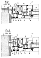
- Figure 3 shows a schematic plan section of a window frame according to the invention with joint open;
- Figure 4 shows a schematic plan section of a window frame according to the invention with sealing functions performed only by abutment seals;
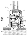
- Figure 5 shows a frame positioned inside the opening of the window frame according to the invention, also shown in figures 3 and 4;
- Figure 6 shows an external ledge frame of the window frame according to the invention;
- Figure 7 shows an internal ledge frame of the window frame according to the invention;
- Figure 8 shows a chair-shaped frame of the window frame according to the invention;
- Figure 9 shows a wing for seal system with open joint seal;
- Figure 10 shows a wing for seal system with abutment seal, also shown in figure 4;
- Figure 11 shows a profile for flat central panel point;
- Figure 12 shows an assembly phase of a thermal insulation joint element on a wing and/or frame profile; and
- Figure 13 shows an assembly phase of an external wing on an internal wing.
- With reference to the figures mentioned, a structure for wing and/or frame of a window frame is shown, indicated overall by
reference number 51. - The
structure 51 comprises afirst frame profile 52 with tubular structure. Afirst wing profile 56 is hinged to thefirst frame profile 52 by means ofhinges 54 fixed to its first wall. - Corresponding to a second wall adjacent to the first wall, the
first frame profile 52 is provided with a pair of appendixes that formseats 58 in whichrawl plugs 60 are locked. Therawl plugs 60 are in their turn fixed, by means of screws, to awall 62. - A
square appendix 64 extends from a third wall, opposite the first one fitted with thehinges 54. Theappendix 64 has a first portion integral with thefirst frame profile 52 and provided with arelief element 66 while a second portion of theappendix 64 is bent square in order not to interfere with theseats 58. A plain connector is provided between the first and second portion of theappendix 64. - A terminal portion not in line with said second portion in order to further ensure that it does not interfere with the
first frame profile 52 is integral with the second portion of theappendix 64. Anotch 68 is also positioned corresponding to the end portion, and the free end of theappendix 64 is rounded. - The
appendix 64 is necessary to fit asecond frame profile 70, also with the help of anothersquare appendix 72, which extends from a corner positioned between the second and third wall of thefirst frame profile 52. - The
second frame profile 70 features a tubular structure that forms one ormore air chambers 74. - One end of the
second frame profile 70 protrudes and contains arounded groove 76 in which the rounded free end of theappendix 64 is inserted as a guide element. - Corresponding to said protruding end a
groove 77 is also provided, which can be used as a seal seat. - From the other end of the second frame profile 70 a
flat element 78 protrudes with free end enlarged and blocked against theprotruding element 66, as engaged elements. A further twoflat elements flat element 78. - The
element 80 is fixed corresponding to the free end of theelement 78 and has a back portion abutting on theappendix 72. - The
appendix 82, on the other hand, blocks aseal 84 also with the help of aprotruding edge 86 of thesecond frame profile 70. - A thermal
insulating element 88, basically U-shaped, is positioned on the other side of theappendix 64. - A first end of the
element 88 extends well beyond the second end. Said first end is provided with a relief element inserted inside thenotch 68. - A second end of the
element 88 is also provided with a relief element which engages with asquare appendix 90, which extends from a corner located between the third wall and a fourth wall of thefirst frame profile 52. An end portion of the second end of theelement 88 is bent in order to form a support for aseal element 92. - It should be noted that another important function of the
element 88 is to act as a block for profile 70 (or forprofile 104 which will be illustrated in further detail below), preventing them coming out of their installation position by means of reciprocal contact ofparts - The
first wing profile 56, which is fixed to thehinge 54, features a rectangular-shaped tubular structure. - A
portion 94 fitted at the end with aseal 96 abutting on thefirst frame profile 52 extends from a corner between a first wall facing the inside of an area limited by the window frame and a second wall facing thefirst frame profile 52. - A third wall, opposite the first one, is fitted with an
appendix 98 identical to theappendix 64 of thefirst frame profile 52 and therefore the details of this appendix are indicated with the same numbers as those already used forappendix 64. From the two corners forming said third wall, twoappendixes second wing profile 104 and a reinforcement element the same aselement 88 and not shown for the sake of simplicity. - The
second wing profile 104, made of plastic, is similar to thesecond frame profile 70 and some numbers are therefore repeated for the sake of simplicity. - In fact, the
second wing profile 104 features a tubular structure formingair chambers 106 inside. Furthermore, a portion withgroove 76 that locks on the end section ofappendix 98, as an engaged element, protrudes from thesecond wing profile 104. Said protruding portion is fitted with aseal 108 which locks on a glass panel orother element 110 supported by thefirst wing profile 56. - On the other side, the
second wing profile 104 features aflat element 112 locked on therelief element 66 of thefirst wing profile 56, like engaged elements, as already indicated for thesecond frame profile 70. Furthermore, aflat element 114 that protrudes from theelement 112 abuts on theseal 92. From theflat element 112, anelement 116 extends which, when the wing is closed, is facing but not in contact with thesecond frame profile 70. - A fourth wall, adjacent to the first and third, is fitted with the hooking
elements 118 to which aprofile 120, fitted at its end with aseal 122 positioned againstelement 110, can be coupled. - In preferred embodiments, the
first frame profile 52 and thefirst wing profile 56 are both made of aluminium, which guarantees sturdiness and at the same time lightness. Thefirst frame profile 70 and thesecond wing profile 104, on the other hand, are made of insulating material such as PVC, polypropylene, polyurethane or other, to ensure heat insulation with easy machining. - A second embodiment of the window frame structure, according to the present invention, is shown in figure 4, where identical or similar elements are indicated with the same numbers as those of the first embodiment described above.
- In said embodiment the
first frame profile 52, thesecond frame profile 70 and thefirst wing profile 56 are the same as those already described, while thesecond wing profile 104 differs from the one of the first embodiment shown in figure 3 and is identical to thesecond frame profile 70. - A
seal 124 is locked inside thegroove 77 of thesecond frame profile 70. When the wing is closed, the seal abuts against theappendix 82 of thesecond wing profile 104 and guarantees the window frame seal. - Figures 5 to 8 show details of the frames of the structure according to the invention where elements identical or similar to those already described are indicated by the same or similar numbers.
- Figure 5 shows a frame positioned inside the opening of the window frame which is the one already described in figures 3 and 4.
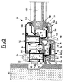
- Figure 6 shows an example of external ledge frame. In this case the
first frame profile 52 is identical to the one of figure 5 while the second frame profile features a portion identical to the second frame profile of figure 5 and a further portion that makes its external profile symmetrical with a central axis (not shown). - Figure 7 shows an example of internal ledge frame. In this case the first frame profile is similar to the frame of figure 5 but features an
elongated portion 126 which extends in the opposite direction from theappendix 64 and is provided with aseat 128 for a seal. Thesecond frame profile 70, on the other hand, is identical to the one shown in figure 5. - Figure 8 shows an example of chair-shaped frame. In this case the
first frame profile 52 is identical to the one shown in figure 7 while thesecond frame profile 70 is identical to the one shown in figure 6. - Figures 9 and 10 show some details of the wings of the structure according to the invention, indicating, with identical or similar numbers, elements identical or similar to the ones already described.
- Figure 9 shows a wing for seal system with open joint seal. Said wing is identical to the one shown in figure 3.
- Figure 10 shows a wing for a seal system with abutment seal. Said wing is identical to the one shown in figure 4.
- Figure 11, on the other hand, shows a profile for flat central panel point. This features a structure identical to that of the frame or wing already described and comprises an
internal element 130 in aluminium and an external element inplastic 132. - The
internal element 130 has a tubular structure and features at one end anelement 134 shaped similarly to theappendix 98 so that theexternal element 132 can be locked on it. In practice theelement 134 features afree portion 136 identical to that of theappendix 98, the latter being extended with asquare element 138 fitted with aprotruding element 140. Furthermore, one end of a further element that forms, together withportion 136 itself, a profile the same as that ofappendix 98, is fixed to thefree portion 136. - The
element 132, in its turn, features a structure similar to that of the second frame profile, shown in figure 6. In particular theelement 132 has a tubular structure with a portion protruding at one end provided with aseat 142 identical toseat 77. - The other end is also protruding and features an abutment element 144. A further
flat element 146 with enlarged end hooked in the protrudingelement 140 is fixed on theexternal element 132. - Assembly of the
second frame profile 70 on thefirst frame profile 52 and of thesecond wing profile 104 on thefirst wing profile 56 is very simple and quick and is performed basically as follows. - The
second frame profile 70 is rested on theappendix 64 and snap-locked onto the latter. In the same way thesecond wing profile 104 is rested on theappendix 98 and snap-locked onto the latter. - When present, the
thermal insulation elements 88 are locked in the same way. - It should be noted that the locking and thermal barrier functions of the
profiles flat element 78 with therelief element 66 and by contact of the flat element 80 (p 114) with theflat element 100. - Figures 12 and 13 show, for example, insertion of the
thermal insulation element 88 and thesecond wing profile 104 on thefirst wing profile 56, referring to the wing in the first embodiment described. - In figure 12 the
element 88 is inserted until it locks as shown by the arrows A, while in figure 13 thesecond frame profile 104 is rested as shown by the arrow B and pressed until it locks as shown by the arrow C. - Furthermore, it is also possible to produce alignment elements inserted directly inside the second frame profile or the second wing profile made of plastic. In the event of fire, the
profile 120 is able to retain theglass 110. - In a preferred embodiment the window frames are made with "European chamber". In this way it is in fact possible to create any type of existing ledge window frame and purchase the accessories at very reasonable prices (since almost all manufacturers of accessories and sub-contractors make them); this avoids procurement from one single exclusive supplier.
- In this way minimum investments can be made with a few customised accessories specifically designed for the particular type of window frame. These accessories are, for example, inversion plugs for open and ledge-ledge joints, seals and angles of open joints and any squares (Monticelli type) required. Profiles like, for example, glass retainers with their angle accessories if necessary, rod profiles etc. are available from various extruded parts manufacturers.
- Furthermore, specific punching machines are not necessary as parts such as squares, cremone bolts, rods, folding wings etc. are universal.
- In practice it has been seen that the structure for a wing and/or frame of a window frame, according to the invention, is particularly advantageous. Furthermore, the different types of frame profiles and the different types of wing profiles are interchangeable in order to meet many different needs without having to produce an excessive number of products.
Claims (11)
- Structure (51) for wing and frame of a window frame comprising, for the production of the above-mentioned wing and frame, a first frame profile (52) and a first wing profile (56) made of metal, a second frame profile (70) and a second wing profile (104) made of plastic and one or two insulating elements (88) whereby said first frame profile (52) is snap-locked to said second frame profile (70) by means of first engaging elements (64, 66, 76, 78) and said first wing profile (56) is snap-locked to said second wing profile (104) by means of second engaging elements (66, 76, 98, 112), said first engaging elements (64, 66, 76, 78) comprise a first appendix (64) integral with said first frame profile (52), on which said second frame profile (70) is locked and where said appendix (64) is inserted inside at least one groove (76) of said second frame profile (70), said second engaging elements (66, 76, 98, 112) comprise a second appendix (98) integral with said first wing profile (56), on which said second wing profile (104) is locked and where said appendix (98) is inserted inside at least one groove (76) of said second wing profile (104), characterised in that- the first and second appendices (64,98) have essentially an L-shape, whereby the free portion extends parallel to the plane of the frame, the second frame profile (70) covers the outer surface of the first appendix (64) and the second wing profile (104) covers the outer surface of the second appendix (98),- first and second appendices (64,98) both feature, close to the end of their free portion, at least one notch (68),- a third appendix (90) is integral with said first frame profile (52) and a fourth appendix (102) is integral with said first wing profile (56)- the insulating element (88) or one of the insulating elements can cover the inner surface of the first (64) or second appendix (98) by inserting it in the respective notch (68) and locking it in the third (90) or fourth appendix (102) respectively, and,- said second frame and wing profiles (70,104) feature a tubular structure forming a set of air chambers (74, 106).
- Structure (51) according to claim 1, characterised in that said appendixes (64, 98) are basically square-shaped.
- Structure (51) according to claim 2, characterised in that a terminal portion of said appendixes (64, 98) is not in line with the same appendixes (64, 98) in order not to interfere with said first frame profile (52) and said first wing profile (56).
- Structure (51) according to claim 3, characterised in that said element (88) acts as a lock for said second frame profile (70) or for said second wing profile (104), preventing them coming out of their installation position by means of mutual contact of the parts (180, 181).
- Structure (51) according to claim 1, characterised in that said free ends of said appendixes (64, 98) and said grooves (76) are rounded.
- Structure (51) according to claim 1, characterised in that corresponding to a protruding end of said second frame profile (70) and said second wing profile (104) at least one groove (77) is provided which can be used as a seal seat.
- Structure (51) according to claim 1, characterised in that said first engaged elements (64, 66, 76, 78) and said second engaged elements (66, 76, 98, 112) comprise at least one flat element (78, 112) which extends from one end of said second frame profile (70) and said second wing profile (104), said flat element (78, 112) having a free end enlarged and locked against a protruding element (66) of said appendixes (64, 98).
- Structure (51) according to claim 7, characterised in that from said flat element (78, 112) at least one other flat element (80, 114) extends, abutting on an appendix (72, 100) of said first frame profile (52) and said second wing profile (56).
- Frame forming a part of a structure of a window frame comprising a first frame profile (52) made of metal, a second frame profile (70) made of plastic and an insulating element (88), whereby said first frame profile (52) is snap-locked by means of first engaging elements (64, 66, 76, 78), said first engaging elements (64, 66, 76, 78) comprise an appendix (64) integral with said first frame profile (52), on which said second frame profile (70) is locked and where said appendix (64) is inserted inside at least one groove (76) of said second frame profile (70), characterised in that- the appendix (64) has essentially an L-shape, whereby the free portion is parallel to the plane of the frame and the second frame profile (104) covers the outer surface of the appendix (64),- the appendix (64) feature, close to its end of its free portion, at least one notch (68)- another appendix (90) is integral with said first frame profile (52),- said insulating element (88) can cover the inner surface of the appendix (64) by inserting it in the respective notch (68) and locking it in the other appendix (90), and- said second frame profile (70) feature a tubular structure forming a set of air chamber (74).
- Wing forming a part of a structure (51) of a window frame comprising a first wing profile (56) made of metal, a second wing profile (104) made of plastic and an insulating element (88), whereby said first wing profile (56) is snap-locked to said second wing profile (104) by means of engaging elements (66, 76, 98, 112), said second engaging elements comprise an appendix (98) integral with said first wing profile (56), on which said second wing profile (104) is locked and where said appendix (98) is inserted inside at least one groove (76) of said second wing profile (104), characterised in that- the appendix (98) has essentially an L-shape, whereby the free portion is parallel to the plane of the wing and the second wing profile (104) covers the outer surface of the appendix (98),- the appendix (98) feature, close to its end of its free portion, at least one notch (68),- another appendix (102) is integral with said first wing profile (56),- said insulating element (88) can cover the inner surface of the appendix (64) by inserting it in the respective notch (68) and locking it in the other appendix (102) integral with said first wing profile (56), and- said second wing profile (104) feature a tubular structure forming a set of air chamber (106).
- Inversion profile forming a part of a structure (51) of a window frame comprising at least one internal element (130) made of metal, an external element (132) made of plastic and an insulating element (88), whereby said at least one internal element (130) is snap-locked to said external element (132) by means of first engaging elements, said first engaging elements comprise an appendix (134) integral with said at least one internal element (130), on which said external element (132) is locked and where said appendix is inserted inside at least one groove of said external element (132), characterised in that- the appendix has essentially an L-shape, whereby the free portion is parallel to the plane of the wing and the external element (132) covers the outer surface of the at least one internal element (130),- said appendix feature, close to its end of its free portion, at least one notch- another appendix (90) is integral with said at least one internal element (130)- said insulating element (88) can cover the inner surface of the appendix by inserting it in the respective notch, and locking it in the other appendix (90) integral with said at least one internal element (130), and- said external element (132) feature a tubular structure forming a set of air chamber.
Applications Claiming Priority (2)
| Application Number | Priority Date | Filing Date | Title |
|---|---|---|---|
| IT2000MI000181A IT1316342B1 (en) | 2000-02-04 | 2000-02-04 | STRUCTURE FOR DOOR AND / OR FRAME OF A WINDOW |
| ITMI200181 | 2000-02-04 |
Publications (3)
| Publication Number | Publication Date |
|---|---|
| EP1122393A2 EP1122393A2 (en) | 2001-08-08 |
| EP1122393A3 EP1122393A3 (en) | 2002-06-26 |
| EP1122393B1 true EP1122393B1 (en) | 2006-04-26 |
Family
ID=11443898
Family Applications (1)
| Application Number | Title | Priority Date | Filing Date |
|---|---|---|---|
| EP01200281A Expired - Lifetime EP1122393B1 (en) | 2000-02-04 | 2001-01-29 | Structure for wing and/or frame of a window frame |
Country Status (4)
| Country | Link |
|---|---|
| EP (1) | EP1122393B1 (en) |
| AT (1) | ATE324508T1 (en) |
| DE (1) | DE60118995D1 (en) |
| IT (1) | IT1316342B1 (en) |
Families Citing this family (4)
| Publication number | Priority date | Publication date | Assignee | Title |
|---|---|---|---|---|
| BE1015839A6 (en) * | 2003-12-18 | 2005-10-04 | Reynaers Aluminium Nv | Window, door or the like and plastic profile applied in it. |
| GB2525183B (en) * | 2014-04-14 | 2021-01-13 | Storm Faith Network Ltd | Fenestration products |
| FR3045094B1 (en) * | 2015-12-10 | 2019-02-01 | Fl Creation | REMOVABLE GLASS ELEMENT |
| EP4144946A1 (en) * | 2021-09-01 | 2023-03-08 | Deceuninck NV | Construction profile, in particular for a window or door frame, a window or door frame comprising such construction profile and a resulting window or door |
Family Cites Families (9)
| Publication number | Priority date | Publication date | Assignee | Title |
|---|---|---|---|---|
| CH330031A (en) * | 1956-10-18 | 1958-05-31 | Metallbau Hirsch | window |
| CH425163A (en) * | 1964-06-17 | 1966-11-30 | Arnd Maurice | Panel frame comprising a support profile carrying a cover profile |
| GB2106579B (en) * | 1981-09-19 | 1984-10-10 | Bkl Extrusions Ltd | Insulated frame member |
| GB2111109B (en) * | 1981-10-20 | 1985-06-26 | Bkl Extrusions Ltd | Insulated window or door frames |
| WO1994025716A1 (en) * | 1993-04-28 | 1994-11-10 | Erwin Gasser | Composite section |
| FI1349U1 (en) * | 1994-02-21 | 1994-05-20 | Jarmo Sjoeholm | Profilkonstruktion |
| DE9422032U1 (en) * | 1994-10-21 | 1997-11-06 | F.W. Brökelmann Aluminiumwerk GmbH & Co, 59469 Ense | Thermally insulated composite profile for window, door frames or the like. |
| GB9508344D0 (en) * | 1995-04-25 | 1995-06-14 | Manse Window Design Ltd | Frame for a closure member and method of mounting a frame |
| GB2303398A (en) * | 1995-07-19 | 1997-02-19 | Thermal Profiles Accessories | Two-part frame with foam plastic infill |
-
2000
- 2000-02-04 IT IT2000MI000181A patent/IT1316342B1/en active
-
2001
- 2001-01-29 EP EP01200281A patent/EP1122393B1/en not_active Expired - Lifetime
- 2001-01-29 DE DE60118995T patent/DE60118995D1/en not_active Expired - Lifetime
- 2001-01-29 AT AT01200281T patent/ATE324508T1/en not_active IP Right Cessation
Also Published As
| Publication number | Publication date |
|---|---|
| DE60118995D1 (en) | 2006-06-01 |
| ITMI20000181A0 (en) | 2000-02-04 |
| ATE324508T1 (en) | 2006-05-15 |
| ITMI20000181A1 (en) | 2001-08-04 |
| EP1122393A2 (en) | 2001-08-08 |
| IT1316342B1 (en) | 2003-04-10 |
| EP1122393A3 (en) | 2002-06-26 |
Similar Documents
| Publication | Publication Date | Title |
|---|---|---|
| US4008552A (en) | Wall structure and elements therefor | |
| US4250673A (en) | Window replacement system | |
| ITMI941678A1 (en) | COMPLEX OF METAL-WOOD COMPOSITE PROFILES FOR WINDOWS | |
| EP1122393B1 (en) | Structure for wing and/or frame of a window frame | |
| RU2760389C2 (en) | Box bar and/or leaf frame bar and door, window or facade element | |
| PL198654B1 (en) | Frame for a window, door or façade element | |
| GB2155087A (en) | Frame component | |
| GB2525183A (en) | Fenestration products | |
| KR102035936B1 (en) | Front door having improved structure for protection against wind and insulation | |
| KR101933354B1 (en) | Insulating fire door with support bar for reinforce | |
| JP3726948B2 (en) | Thermal insulation frame | |
| WO1999029995A1 (en) | Set of metal sections for the construction of continuous faces for buildings | |
| JP6726963B2 (en) | Curtain wall structure | |
| WO2019130367A1 (en) | Window frame | |
| EP1298270A2 (en) | Pivotable shutter panel assembly | |
| CN210178188U (en) | Window connecting structure | |
| KR200369502Y1 (en) | plain slat structure of panel shutter | |
| JP7019384B2 (en) | Composite sash structure | |
| JP2916989B2 (en) | curtain wall | |
| JP3266233B2 (en) | Sliding window | |
| GB2277756A (en) | Cavity closures | |
| KR101873023B1 (en) | Sash with waterproof function and construction method thereof | |
| KR200175792Y1 (en) | Structure of sliding window | |
| KR200252271Y1 (en) | Chassis Structure for Window Frame | |
| FI60428C (en) | TILLAEGGSGLASKONSTRUKTION |
Legal Events
| Date | Code | Title | Description |
|---|---|---|---|
| PUAI | Public reference made under article 153(3) epc to a published international application that has entered the european phase |
Free format text: ORIGINAL CODE: 0009012 |
|
| AK | Designated contracting states |
Kind code of ref document: A2 Designated state(s): AT BE CH CY DE DK ES FI FR GB GR IE IT LI LU MC NL PT SE TR |
|
| AX | Request for extension of the european patent |
Free format text: AL;LT;LV;MK;RO;SI |
|
| PUAL | Search report despatched |
Free format text: ORIGINAL CODE: 0009013 |
|
| AK | Designated contracting states |
Kind code of ref document: A3 Designated state(s): AT BE CH CY DE DK ES FI FR GB GR IE IT LI LU MC NL PT SE TR |
|
| AX | Request for extension of the european patent |
Free format text: AL;LT;LV;MK;RO;SI |
|
| 17P | Request for examination filed |
Effective date: 20021126 |
|
| AKX | Designation fees paid |
Designated state(s): AT BE CH CY DE DK ES FI FR GB GR IE IT LI LU MC NL PT SE TR |
|
| AXX | Extension fees paid |
Extension state: LT Payment date: 20021126 Extension state: LV Payment date: 20021126 Extension state: SI Payment date: 20021126 |
|
| 17Q | First examination report despatched |
Effective date: 20030528 |
|
| GRAP | Despatch of communication of intention to grant a patent |
Free format text: ORIGINAL CODE: EPIDOSNIGR1 |
|
| GRAS | Grant fee paid |
Free format text: ORIGINAL CODE: EPIDOSNIGR3 |
|
| GRAA | (expected) grant |
Free format text: ORIGINAL CODE: 0009210 |
|
| AK | Designated contracting states |
Kind code of ref document: B1 Designated state(s): AT BE CH CY DE DK ES FI FR GB GR IE IT LI LU MC NL PT SE TR |
|
| AX | Request for extension of the european patent |
Extension state: LT LV SI |
|
| PG25 | Lapsed in a contracting state [announced via postgrant information from national office to epo] |
Ref country code: IT Free format text: LAPSE BECAUSE OF FAILURE TO SUBMIT A TRANSLATION OF THE DESCRIPTION OR TO PAY THE FEE WITHIN THE PRESCRIBED TIME-LIMIT;WARNING: LAPSES OF ITALIAN PATENTS WITH EFFECTIVE DATE BEFORE 2007 MAY HAVE OCCURRED AT ANY TIME BEFORE 2007. THE CORRECT EFFECTIVE DATE MAY BE DIFFERENT FROM THE ONE RECORDED. Effective date: 20060426 Ref country code: AT Free format text: LAPSE BECAUSE OF FAILURE TO SUBMIT A TRANSLATION OF THE DESCRIPTION OR TO PAY THE FEE WITHIN THE PRESCRIBED TIME-LIMIT Effective date: 20060426 Ref country code: CH Free format text: LAPSE BECAUSE OF FAILURE TO SUBMIT A TRANSLATION OF THE DESCRIPTION OR TO PAY THE FEE WITHIN THE PRESCRIBED TIME-LIMIT Effective date: 20060426 Ref country code: FI Free format text: LAPSE BECAUSE OF FAILURE TO SUBMIT A TRANSLATION OF THE DESCRIPTION OR TO PAY THE FEE WITHIN THE PRESCRIBED TIME-LIMIT Effective date: 20060426 Ref country code: BE Free format text: LAPSE BECAUSE OF FAILURE TO SUBMIT A TRANSLATION OF THE DESCRIPTION OR TO PAY THE FEE WITHIN THE PRESCRIBED TIME-LIMIT Effective date: 20060426 Ref country code: NL Free format text: LAPSE BECAUSE OF FAILURE TO SUBMIT A TRANSLATION OF THE DESCRIPTION OR TO PAY THE FEE WITHIN THE PRESCRIBED TIME-LIMIT Effective date: 20060426 Ref country code: LI Free format text: LAPSE BECAUSE OF FAILURE TO SUBMIT A TRANSLATION OF THE DESCRIPTION OR TO PAY THE FEE WITHIN THE PRESCRIBED TIME-LIMIT Effective date: 20060426 |
|
| REG | Reference to a national code |
Ref country code: GB Ref legal event code: FG4D |
|
| REG | Reference to a national code |
Ref country code: IE Ref legal event code: FG4D |
|
| REF | Corresponds to: |
Ref document number: 60118995 Country of ref document: DE Date of ref document: 20060601 Kind code of ref document: P |
|
| PG25 | Lapsed in a contracting state [announced via postgrant information from national office to epo] |
Ref country code: SE Free format text: LAPSE BECAUSE OF FAILURE TO SUBMIT A TRANSLATION OF THE DESCRIPTION OR TO PAY THE FEE WITHIN THE PRESCRIBED TIME-LIMIT Effective date: 20060726 Ref country code: DK Free format text: LAPSE BECAUSE OF FAILURE TO SUBMIT A TRANSLATION OF THE DESCRIPTION OR TO PAY THE FEE WITHIN THE PRESCRIBED TIME-LIMIT Effective date: 20060726 |
|
| PG25 | Lapsed in a contracting state [announced via postgrant information from national office to epo] |
Ref country code: DE Free format text: LAPSE BECAUSE OF FAILURE TO SUBMIT A TRANSLATION OF THE DESCRIPTION OR TO PAY THE FEE WITHIN THE PRESCRIBED TIME-LIMIT Effective date: 20060727 |
|
| PG25 | Lapsed in a contracting state [announced via postgrant information from national office to epo] |
Ref country code: ES Free format text: LAPSE BECAUSE OF FAILURE TO SUBMIT A TRANSLATION OF THE DESCRIPTION OR TO PAY THE FEE WITHIN THE PRESCRIBED TIME-LIMIT Effective date: 20060806 |
|
| PG25 | Lapsed in a contracting state [announced via postgrant information from national office to epo] |
Ref country code: PT Free format text: LAPSE BECAUSE OF FAILURE TO SUBMIT A TRANSLATION OF THE DESCRIPTION OR TO PAY THE FEE WITHIN THE PRESCRIBED TIME-LIMIT Effective date: 20060926 |
|
| LTIE | Lt: invalidation of european patent or patent extension |
Effective date: 20060426 |
|
| REG | Reference to a national code |
Ref country code: CH Ref legal event code: PL |
|
| NLV1 | Nl: lapsed or annulled due to failure to fulfill the requirements of art. 29p and 29m of the patents act | ||
| PG25 | Lapsed in a contracting state [announced via postgrant information from national office to epo] |
Ref country code: MC Free format text: LAPSE BECAUSE OF NON-PAYMENT OF DUE FEES Effective date: 20070131 |
|
| PLBE | No opposition filed within time limit |
Free format text: ORIGINAL CODE: 0009261 |
|
| STAA | Information on the status of an ep patent application or granted ep patent |
Free format text: STATUS: NO OPPOSITION FILED WITHIN TIME LIMIT |
|
| 26N | No opposition filed |
Effective date: 20070129 |
|
| EN | Fr: translation not filed | ||
| GBPC | Gb: european patent ceased through non-payment of renewal fee |
Effective date: 20070129 |
|
| PG25 | Lapsed in a contracting state [announced via postgrant information from national office to epo] |
Ref country code: GB Free format text: LAPSE BECAUSE OF NON-PAYMENT OF DUE FEES Effective date: 20070129 |
|
| PG25 | Lapsed in a contracting state [announced via postgrant information from national office to epo] |
Ref country code: IE Free format text: LAPSE BECAUSE OF NON-PAYMENT OF DUE FEES Effective date: 20070129 |
|
| PG25 | Lapsed in a contracting state [announced via postgrant information from national office to epo] |
Ref country code: FR Free format text: LAPSE BECAUSE OF FAILURE TO SUBMIT A TRANSLATION OF THE DESCRIPTION OR TO PAY THE FEE WITHIN THE PRESCRIBED TIME-LIMIT Effective date: 20070309 Ref country code: GR Free format text: LAPSE BECAUSE OF FAILURE TO SUBMIT A TRANSLATION OF THE DESCRIPTION OR TO PAY THE FEE WITHIN THE PRESCRIBED TIME-LIMIT Effective date: 20060727 |
|
| PGFP | Annual fee paid to national office [announced via postgrant information from national office to epo] |
Ref country code: TR Payment date: 20080110 Year of fee payment: 8 |
|
| PG25 | Lapsed in a contracting state [announced via postgrant information from national office to epo] |
Ref country code: FR Free format text: LAPSE BECAUSE OF FAILURE TO SUBMIT A TRANSLATION OF THE DESCRIPTION OR TO PAY THE FEE WITHIN THE PRESCRIBED TIME-LIMIT Effective date: 20060426 |
|
| PG25 | Lapsed in a contracting state [announced via postgrant information from national office to epo] |
Ref country code: LU Free format text: LAPSE BECAUSE OF NON-PAYMENT OF DUE FEES Effective date: 20070129 Ref country code: CY Free format text: LAPSE BECAUSE OF FAILURE TO SUBMIT A TRANSLATION OF THE DESCRIPTION OR TO PAY THE FEE WITHIN THE PRESCRIBED TIME-LIMIT Effective date: 20060426 |
|
| PG25 | Lapsed in a contracting state [announced via postgrant information from national office to epo] |
Ref country code: IT Free format text: LAPSE BECAUSE OF NON-PAYMENT OF DUE FEES Effective date: 20090129 |
|
| PGRI | Patent reinstated in contracting state [announced from national office to epo] |
Ref country code: IT Effective date: 20110616 |
|
| PG25 | Lapsed in a contracting state [announced via postgrant information from national office to epo] |
Ref country code: TR Free format text: LAPSE BECAUSE OF NON-PAYMENT OF DUE FEES Effective date: 20110727 |
|
| PG25 | Lapsed in a contracting state [announced via postgrant information from national office to epo] |
Ref country code: TR Free format text: LAPSE BECAUSE OF NON-PAYMENT OF DUE FEES Effective date: 20090129 |
|
| PGFP | Annual fee paid to national office [announced via postgrant information from national office to epo] |
Ref country code: IT Payment date: 20140130 Year of fee payment: 14 |
|
| PG25 | Lapsed in a contracting state [announced via postgrant information from national office to epo] |
Ref country code: IT Free format text: LAPSE BECAUSE OF NON-PAYMENT OF DUE FEES Effective date: 20150129 |