EP1122152A2 - Verstärkungselement mit Hohlprofilen und thermisch expandierbares Verstärkungsmaterial - Google Patents
Verstärkungselement mit Hohlprofilen und thermisch expandierbares Verstärkungsmaterial Download PDFInfo
- Publication number
- EP1122152A2 EP1122152A2 EP01101684A EP01101684A EP1122152A2 EP 1122152 A2 EP1122152 A2 EP 1122152A2 EP 01101684 A EP01101684 A EP 01101684A EP 01101684 A EP01101684 A EP 01101684A EP 1122152 A2 EP1122152 A2 EP 1122152A2
- Authority
- EP
- European Patent Office
- Prior art keywords
- carrier
- reinforcing
- reinforcing member
- reinforcing material
- walls
- Prior art date
- Legal status (The legal status is an assumption and is not a legal conclusion. Google has not performed a legal analysis and makes no representation as to the accuracy of the status listed.)
- Withdrawn
Links
- 230000003014 reinforcing effect Effects 0.000 title claims abstract description 76
- 239000012779 reinforcing material Substances 0.000 title claims description 95
- 239000000463 material Substances 0.000 claims abstract description 58
- 238000005187 foaming Methods 0.000 claims description 24
- 239000000853 adhesive Substances 0.000 claims description 11
- 230000001070 adhesive effect Effects 0.000 claims description 11
- IISBACLAFKSPIT-UHFFFAOYSA-N bisphenol A Chemical compound C=1C=C(O)C=CC=1C(C)(C)C1=CC=C(O)C=C1 IISBACLAFKSPIT-UHFFFAOYSA-N 0.000 claims description 10
- 239000004793 Polystyrene Substances 0.000 claims description 6
- VYPSYNLAJGMNEJ-UHFFFAOYSA-N Silicium dioxide Chemical compound O=[Si]=O VYPSYNLAJGMNEJ-UHFFFAOYSA-N 0.000 claims description 6
- 229920001400 block copolymer Polymers 0.000 claims description 6
- 229920002223 polystyrene Polymers 0.000 claims description 6
- 229920001971 elastomer Polymers 0.000 claims description 5
- 239000011521 glass Substances 0.000 claims description 5
- 239000004005 microsphere Substances 0.000 claims description 5
- 239000006229 carbon black Substances 0.000 claims description 4
- 239000004850 liquid epoxy resins (LERs) Substances 0.000 claims description 4
- 239000004604 Blowing Agent Substances 0.000 claims description 3
- 239000003054 catalyst Substances 0.000 claims description 3
- 239000003795 chemical substances by application Substances 0.000 claims description 3
- 239000000377 silicon dioxide Substances 0.000 claims description 3
- 239000007787 solid Substances 0.000 claims description 3
- 238000004519 manufacturing process Methods 0.000 abstract description 6
- 239000000203 mixture Substances 0.000 description 11
- 230000002787 reinforcement Effects 0.000 description 9
- 230000008901 benefit Effects 0.000 description 6
- FACXGONDLDSNOE-UHFFFAOYSA-N buta-1,3-diene;styrene Chemical compound C=CC=C.C=CC1=CC=CC=C1.C=CC1=CC=CC=C1 FACXGONDLDSNOE-UHFFFAOYSA-N 0.000 description 6
- 229920000468 styrene butadiene styrene block copolymer Polymers 0.000 description 6
- 239000000057 synthetic resin Substances 0.000 description 6
- 229920003002 synthetic resin Polymers 0.000 description 6
- 230000004913 activation Effects 0.000 description 5
- XOZUGNYVDXMRKW-AATRIKPKSA-N azodicarbonamide Chemical compound NC(=O)\N=N\C(N)=O XOZUGNYVDXMRKW-AATRIKPKSA-N 0.000 description 5
- 239000006260 foam Substances 0.000 description 5
- 229920000459 Nitrile rubber Polymers 0.000 description 4
- XLOMVQKBTHCTTD-UHFFFAOYSA-N Zinc monoxide Chemical compound [Zn]=O XLOMVQKBTHCTTD-UHFFFAOYSA-N 0.000 description 4
- 239000004677 Nylon Substances 0.000 description 3
- NTXGQCSETZTARF-UHFFFAOYSA-N buta-1,3-diene;prop-2-enenitrile Chemical compound C=CC=C.C=CC#N NTXGQCSETZTARF-UHFFFAOYSA-N 0.000 description 3
- XXOYNJXVWVNOOJ-UHFFFAOYSA-N fenuron Chemical compound CN(C)C(=O)NC1=CC=CC=C1 XXOYNJXVWVNOOJ-UHFFFAOYSA-N 0.000 description 3
- 238000010438 heat treatment Methods 0.000 description 3
- 239000002184 metal Substances 0.000 description 3
- 229910052751 metal Inorganic materials 0.000 description 3
- 229920001778 nylon Polymers 0.000 description 3
- 239000004156 Azodicarbonamide Substances 0.000 description 2
- 235000019399 azodicarbonamide Nutrition 0.000 description 2
- QGBSISYHAICWAH-UHFFFAOYSA-N dicyandiamide Chemical compound NC(N)=NC#N QGBSISYHAICWAH-UHFFFAOYSA-N 0.000 description 2
- LRCFXGAMWKDGLA-UHFFFAOYSA-N dioxosilane;hydrate Chemical compound O.O=[Si]=O LRCFXGAMWKDGLA-UHFFFAOYSA-N 0.000 description 2
- 239000003822 epoxy resin Substances 0.000 description 2
- 239000008240 homogeneous mixture Substances 0.000 description 2
- 238000009434 installation Methods 0.000 description 2
- 238000002844 melting Methods 0.000 description 2
- 230000008018 melting Effects 0.000 description 2
- 239000008188 pellet Substances 0.000 description 2
- 229920000647 polyepoxide Polymers 0.000 description 2
- 239000004616 structural foam Substances 0.000 description 2
- 238000003466 welding Methods 0.000 description 2
- 239000011787 zinc oxide Substances 0.000 description 2
- KUBDPQJOLOUJRM-UHFFFAOYSA-N 2-(chloromethyl)oxirane;4-[2-(4-hydroxyphenyl)propan-2-yl]phenol Chemical compound ClCC1CO1.C=1C=C(O)C=CC=1C(C)(C)C1=CC=C(O)C=C1 KUBDPQJOLOUJRM-UHFFFAOYSA-N 0.000 description 1
- -1 Celogen AZ 765® Chemical compound 0.000 description 1
- 230000002411 adverse Effects 0.000 description 1
- 230000009286 beneficial effect Effects 0.000 description 1
- 238000007664 blowing Methods 0.000 description 1
- 239000000969 carrier Substances 0.000 description 1
- 230000008859 change Effects 0.000 description 1
- 238000006243 chemical reaction Methods 0.000 description 1
- 239000002131 composite material Substances 0.000 description 1
- 239000000356 contaminant Substances 0.000 description 1
- 238000001816 cooling Methods 0.000 description 1
- 238000006073 displacement reaction Methods 0.000 description 1
- 238000009826 distribution Methods 0.000 description 1
- 239000000428 dust Substances 0.000 description 1
- 230000003028 elevating effect Effects 0.000 description 1
- 230000009969 flowable effect Effects 0.000 description 1
- 239000004615 ingredient Substances 0.000 description 1
- 238000002347 injection Methods 0.000 description 1
- 239000007924 injection Substances 0.000 description 1
- 238000001746 injection moulding Methods 0.000 description 1
- 230000004048 modification Effects 0.000 description 1
- 238000012986 modification Methods 0.000 description 1
- 239000003973 paint Substances 0.000 description 1
- 239000000049 pigment Substances 0.000 description 1
- 239000000843 powder Substances 0.000 description 1
- 239000000565 sealant Substances 0.000 description 1
- 230000035939 shock Effects 0.000 description 1
- 238000005728 strengthening Methods 0.000 description 1
- 150000003673 urethanes Chemical class 0.000 description 1
- 239000003981 vehicle Substances 0.000 description 1
Images


Classifications
-
- B—PERFORMING OPERATIONS; TRANSPORTING
- B29—WORKING OF PLASTICS; WORKING OF SUBSTANCES IN A PLASTIC STATE IN GENERAL
- B29C—SHAPING OR JOINING OF PLASTICS; SHAPING OF MATERIAL IN A PLASTIC STATE, NOT OTHERWISE PROVIDED FOR; AFTER-TREATMENT OF THE SHAPED PRODUCTS, e.g. REPAIRING
- B29C44/00—Shaping by internal pressure generated in the material, e.g. swelling or foaming ; Producing porous or cellular expanded plastics articles
- B29C44/02—Shaping by internal pressure generated in the material, e.g. swelling or foaming ; Producing porous or cellular expanded plastics articles for articles of definite length, i.e. discrete articles
- B29C44/12—Incorporating or moulding on preformed parts, e.g. inserts or reinforcements
- B29C44/18—Filling preformed cavities
-
- B—PERFORMING OPERATIONS; TRANSPORTING
- B62—LAND VEHICLES FOR TRAVELLING OTHERWISE THAN ON RAILS
- B62D—MOTOR VEHICLES; TRAILERS
- B62D29/00—Superstructures, understructures, or sub-units thereof, characterised by the material thereof
- B62D29/001—Superstructures, understructures, or sub-units thereof, characterised by the material thereof characterised by combining metal and synthetic material
- B62D29/002—Superstructures, understructures, or sub-units thereof, characterised by the material thereof characterised by combining metal and synthetic material a foamable synthetic material or metal being added in situ
Definitions
- This invention concerns the use of thermally expansible foaming materials, particularly thermally expansible foaming structural reinforcing materials, which are coupled to a beam-shaped carrier by a separate fastening means to provide additional localized stiffness to frames, rails, cavities and other structural members.
- a separate fastening means to provide additional localized stiffness to frames, rails, cavities and other structural members.
- Such a member may be useful in architectural, automotive, aviation, marine, or any other applications where increased support or stiffness would reduce vibration, noise, and/or fatigue propagation, or would provide reinforcement to enhance structural strength or provide energy management during crash, crush or impact encounters.
- foamable materials may be used to bond together separate components.
- Structural foams, urethanes, and thermally expansible foaming materials have been used to enhance acoustic performance and provide structural rigidity.
- thermally expansible structural reinforcing materials used on carriers in the automotive field are illustrated in U.S. Patent No. 5,194,199 to Thum, 5,344,208 to Bien et al., and U.S. Patent Nos. 5,575,526 and 5,755,486 to Wycech.
- Another example of the use of thermally expansible materials on a carrier and used primarily as a baffle composition is shown in U.S. Patent No. 5,506,025 to Otto et al.
- An example of the use of foamable material on a beam-shaped structure in a piling is shown in U.S. Patent No. 4,019,301 to Fox et al.
- the reinforcing member of the present invention provides significant advantages in manufacturing, handling and use over prior carrier and expansible foaming reinforcing material combinations.
- the present invention enjoys the benefits of utilizing an initially non-tacky reinforcing composition and a carrier which readily receives the material, enables its orientation to be presented and bond to against various opposing surfaces of an adjacent or surrounding structural member after foaming and expansion, and provides excellent load distribution to stiffen and reinforce the structural member.
- the present invention includes a beam shaped carrier, thermally expansible foaming reinforcing material for bonding to and interconnecting the carrier to a structural member, and fastening means separate from the reinforcing material for holding the reinforcing material on the carrier.
- the beam shaped carrier can be variously configured to conform to or be different from the opposing surface of the structural member which is to be reinforced, and as used herein includes not only conventional I-beam shapes, but also beams which present additional strengthening components and surfaces for attachment of the reinforcing material thereto, and substantially solid block-shaped beams.
- the reinforcing material is preferably initially non-tacky and is thermally expansible and foams, such as by internal chemical reaction or more preferably by the external application of heat.
- the reinforcing material is thermally expansible, either by internally created thermal energy or by the external application of heat to activate the material.
- thermally expansible means both internally created thermal energy and the external application of heat to expand and foam the reinforcing material.
- the thermally expansible reinforcing material is preferably a synthetic resin-based material which foams when subjected to temperatures achieved during baking in a manufacturing process (e.g., such as during the paint and powder coat bake stage of automobile manufacturing processes).
- the expansion temperature of the material should be at least about 300°F.
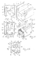
- an automobile body 20 which presents one field of use for the present invention.
- the automobile body 20 includes several interconnected frame elements that define a passenger compartment 22, trunk 24, doorways 26, windows 28, engine compartment 30 and wheel wells 32.
- the reinforcing members 34 of the present invention may be used at a variety of locations within the automobile, but the side rails 36 and cross-members within the engine compartment demonstrate one structural component needing reinforcement to provide stiffening. While a passenger vehicle is illustrated in Fig. 1, it may be appreciated that trucks are another type of automobile as defined in this application for receipt of the present invention.
- FIG.2 and 3 One such reinforcing member 34a is shown in Figs.2 and 3 and includes a carrier 38, thermally expansible structural reinforcing material 39 provided in reinforcing material elements 40 and 42, and fastener 44.
- the side rails 36 are typically enclosed, such as by a plate 46 which is shown as a floor pan 48 being positioned onto the channel 50 of the side rail 36.
- the channel 50 includes a base wall 52 and two upright and substantially parallel sidewalls 54 and 56.
- One particularly preferred composition for use as material 39 is commercialized under the name SikaReinforcer (Sika Corporation, Madison Heights, Michigan).
- the most preferred material 39 comprises: from about 20-30% by weight of a styrene-butadiene-styrene (SBS) block co-polymer (e.g., Fina Clear 530® ); from about 5-20% by weight of a polystyrene (e.g., Fina Crystal 500® and Fina Crystal 535® ); from about 30-45% by weight of a bisphenol A-based liquid epoxy resin (e.g.
- SBS styrene-butadiene-styrene
- Araldite 6010® and Epon 71® from about 0.5-5% by weight of a pigment such as carbon black; up to about 5% by weight butadiene acrylonitrile rubber (Nipol 1411); from about 1-10% by weight hydrated amorphous silica (HiSil 233); from about 10-20% by weight glass microspheres (Scotchlite S60); from about 0.1-5% by weight of a blowing agent such as azodicarbonamide (e.g., Celogen AZ 765® , Celogen AZ 754A® , and Celogen AZ 130® ); from about 0.1-5% by weight of a catalyst such as N, N, dimethyl phenyl urea (U405); from about 0.1-5% by weight of a curing agent such as dicyandiamide (DDA 10); and up to about 5% by weight of a "kicker" such as zinc oxide to lower the blowing temperature, with all percents by weight being based upon the total weight of the material taken
- a particularly preferred composition of the material 39 comprises about 12.94% polystyrene, about 23.22% SBS block copolymer, about 0.57% carbon black, about 1.90% butadiene acrylonitrile rubber, about 4.28% hydrated amorphous silica, about 38.07% bisphenol A-based liquid epoxy resin, about 14.75% glass microspheres, about 0.46% zinc oxide, about 2.85% dicyandiamide, about 0.38% N,N dimethyl phenyl urea, and about 0.57% azodicarbonamide.
- the foregoing may be adjusted such that the polystyrene is reduced to about 12.63%, the SBS block copolymer is reduced to about 22.59%, and the butadiene acrylonitrile rubber is increased to about 2.85%.
- the material 39 can be formed by mixing the SBS block co-polymer with a small portion (about 1/40th of the total amount) of the bisphenol A-based liquid epoxy resin in a heated mixer until the temperature of the mixer reaches from about 240-260°F (the temperature of the mixture within the mixer is at least about 175°F), and the mixture is substantially homogeneous, at which time the polystyrene is added to the mixer and mixing is continued. After the polystyrene is substantially mixed with the SBS block co-polymer/epoxy resin mixture, the remainder ofthe bisphenol A-based epoxy resin is slowly added to the mixer, stopping and starting the mixer as necessary, with the ingredients being thoroughly mixed to obtain a substantially homogeneous mixture.
- the desired amount of this mixture is placed in a heated mixer (set at a temperature of about 250°F) and mixing is commenced. While mixing, the carbon black and rubber are added to the mixer and mixing is stopped once a homogeneous mixture is obtained within the mixer. Either the silica or glass microspheres is added to the mixer, and mixing is resumed and continued until the mixture is homogeneous. This step is repeated, adding the other of the silica or glass microspheres.
- the temperature of the mixer is then set to a temperature below 160°F, the blowing agent(s), catalyst(s), kicker, and curing agent(s) are added, and mixing is resumed and continued only until the mixture is homogeneous.
- the resulting mixture is then preferably extruded into strands (at an extruder temperature of 170-180°F and screw rotation speeds of about 400 rpm) and cut into pellets.
- the pellets are then injection molded at a temperature of about 180-200°F using injection molding equipment designed to form the desired shape of the expandable member 12 to be attached to the carrier 38.
- the carrier 38 is presented in the form of an I-beam which includes an upright web 58 and two parallel end walls 60 and 62 at the ends of the web.
- the end walls 60 and 62 each include a plurality of holes 64 therethrough.
- the carrier 36 presents a longitudinal axis which is aligned with and preferably extends along the longitudinal axis of the channel 50.
- the foamable material elements 40 and 42 are attached on the outwardly oriented surfaces 66 and 68 of end walls 60 and 62, respectively, thereby being oriented for engaging the cap 46 and base wall 52, respectively upon foaming.
- the foamable material elements 40 and 42 each include openings 70 aligned with the holes 64 through the carrier 38, to thereby receive mounting component 44.
- Mounting component 44 as used in the first embodiment shown in Figs.
- a mechanical fastener such as a push pin 72, which may be of synthetic resin and have a shank extending through the foamable material elements 40 and 42 and through the carrier 38 so as to hold the elements 40 and 42 on the carrier 38 prior to foaming.
- the push pin 72 for example of nylon and having a higher melting temperature than the foamable material 39, may have ridges along the shank to grip the foamable material elements 40 and 42, and the holes 64 and openings 70 may be slightly larger than the shank to permit some limited flexibility to allow the foamable material elements 40 and 42 to absorb impact.
- the reinforcing member 34a is placed into the channel 50 whereby the foamable material element 40 contacts the base wall 52 and the foamable material element 42 is in close proximity to the plate 46.
- the plate 46 is structurally bonded to the channel 50 with the reinforcing member adding rigidity thereto.
- Figs. 4 and 5 illustrate a second embodiment 34b of the reinforcing member.
- the carrier 3 8b and reinforcing material elements 40b and 42b are configured and positioned similarly to that shown in Figs. 2 and 3, with the exception that no holes or openings are required.
- Foamable material elements 40b and 42b are instead fastened to the carrier 38b by mounting component 44b provided as structural tape 74.
- the structural tape 74 is known to those skilled in the art, and may be embedded in the elements 40 or 42 or provided with adhesive on both sides 76 and 78 thereof, and is provided as thin strips in order to maximize bonding of the thermally expansible reinforcing material to the carrier after activation..
- Figs. 6 and 7 illustrate a third embodiment 34c of the reinforcing member.
- the carrier 80 thereof includes a central rectangular box beam 82, an upper web 84 and a lower web 86, each with a respective parallel end walls 60 and 62, again without holes therein.
- the box beam 82 presents a top panel 88, bottom panel 90, and side panels 92 and 94.
- the side panels 92 and 94 enable additional structural reinforcing elements 96 and 98 of thermally expansible structural reinforcing material 39 to be attached thereto using the structural tape 74, and thus permits additional bonding of the carrier to the side walls 54 and 56, respectively of the channel 50 and adds both horizontal and vertical reinforcement to the surrounding structural member to provide a reinforced structural member after foaming, expansion and bonding of the reinforcing material elements.
- Figs. 8 and 9 illustrate a fourth embodiment 34d of the reinforcing member.
- the carrier 100 presents opposed, parallel side panels 102 and 104, each having an upper edge 106 and a lower edge 108.
- Three substantially parallel horizontal webs 110, 112, and 114 are positioned between the side panels 102 and 104 and positioned interiorly of the edges 106 and 108.
- the positioning of the uppermost web 110 and the lowermost web 114 present flanges 116 which serve as the mounting component 44 to fasten the elements to the carrier.
- Central web 112 also lies in a horizontal plane as viewed in Figs. 8 and 9, but it may be appreciated that the carrier 100 may be oriented 90 ° to that shown.
- the thermally expansible structural reinforcing material 39 is provided as side reinforcing material elements 118 and 120 coupled by adhesive 121 to the outer faces of the side panels 104 and 106, and upper reinforcing material element 122 and lower reinforcing material element 124 are mounted by their nibs 126 which frictionally engage the flanges 116 to hold the upper and lower reinforcing material elements in place.
- the carrier 100 is bonded to both the plate and the channel to provide a reinforced structural member.
- Figs. 10 and 11 show a fifth embodiment 34e of the reinforcing member hereof, which is similar to the embodiment 34b shown in Figs. 4 and 5.
- the H-beam carrier 38e is oriented at 90° to that shown in Figs. 2 and 3 whereby thermally expansible structural reinforcing material 39 is provided as left and right side structural reinforcing material elements 128 and 130 on respective parallel and opposed left and right end walls 132 and 134 interconnected by web 136.
- Structural tape 74 is the mounting component which fastens the elements 128 and 130 to the carrier 38.
- each of the end walls is supported on the base wall 52 and upon foaming, expansion and bonding, the elements 128 and 130 foam and expand to engage and bond the carrier 38e to the sidewalls 54 and 56, and may expand upwardly to bond the plate 46 to the channel 50 as a reinforced structural member.
- Figs. 12 and 13 illustrate a sixth embodiment 34f of the reinforcing member hereof, similar to the fifth embodiment but wherein the carrier 132 is modified whereby each of the first and second end walls 134 and 136 are provided with end flanges 138, 140, 142 and 144 which are horizontally oriented. End flanges 138 and 140 are co-planar and opposite plate 46, and end flanges 142 and 144 are co-planar, parallel to the end flanges 138 and 140, and opposite base wall 52.
- the thermally expansible structural reinforcing material 39 is provided in left and right side structural reinforcing material elements 146 and 148 are connected to the left and right end walls by push pins 72, and also by push pins 72 on end flange structural reinforcing material elements 150, 152, 154 and 156.
- the push pins 72 function as described in reference to the embodiment shown in Figs. 2 and 3, wherein holes are provided in the carrier which are aligned with openings in the foamable material elements to receive the mechanical fasteners therethrough.
- at least two mechanical fasteners are provided for each element to maintain alignment. After foaming, expansion and bonding, the thermally expansible structural reinforcing material bonds the carrier to the channel and plate to provide a resulting reinforced structural member.
- Figs. 14 and 15 illustrate a seventh embodiment 34g of the reinforcing member of the present invention, wherein the carrier 132 is shown oriented 90 ° relative to its position shown in Figs. 12 and 13, and wherein the thermally expansible structural reinforcing material 39 is provided in upper and lower structural reinforcing material elements 158 and 160.
- the upper element 158 extends around corners 162 and 164 to overly end flanges 138 and 142, while the lower element 160 extends around corners 166 and 168 to overly end flanges 140 and 144.
- the elements 158 and 160 may be temporarily secured to the carrier 132 by narrow lines of adhesive 170 applied intermediate the carrier 132 and the elements 158 and 160, as after foaming the material 39 itself bonds to the carrier.
- the upper and lower structural reinforcing material elements 158 and 160 then not only also bond to the cap 46 and the base wall 52, respectively, but also too sidewalls 54 and 56. Further, the end flanges resist lateral displacement and dislodgement of the structural reinforcing material elements 148 and 150 as viewed in Fig. 14. After foaming, expansion and bonding, the elements bond the carrier to the plate and channel to provide a reinforced structural member.
- Figs. 16 and 17 illustrate an eighth embodiment 34h of the reinforcing member of the present invention, wherein the carrier 38 of Figs. 2 and 3 is employed (again shown without holes), but the foamable material 39 is configured with upper structural reinforcing material element 172 and lower structural reinforcing material element 174 wrap around the respective end walls 60 and 62 to partially extend along the web-facing sides of the end walls.
- the edges 176, 178, 180 and 182 of the end walls thus act as a fastener and are received in corresponding slots 184, 186, 188 and 190 in the foamable material to mechanically engage and hold the foamable material 39 to the carrier 38.
- Thin lines of adhesive 170 may be used as a further fastener to inhibit relative longitudinal movement between the carrier 38 and the upper and lower elements 172 and 174.
- the lines of adhesive may be narrow, as they are provided only to inhibit longitudinal movement of the elements prior to foaming, with the majority of the contact between the reinforcing material elements and walls 60 and 62 being free of adhesive to permit bonding therebetween. After foaming, expansion and bonding, the material 39 bonds the carrier to the plate and the channel to provide a reinforced structural member.
- Figs. 18, 19 and 20 illustrate a ninth embodiment 34i of the present invention, wherein the carrier 192 is configured to change in vertical elevation along its longitudinal length, and thus conform to a frame member of an automobile which presents a hump or bump therealong but nonetheless would benefit by reinforcement.
- the carrier 192 is generally I-beam shaped when viewed in section, as in Fig. 21, and may be a composite carrier formed by welding or fasting two generally C-shaped channels 193 and 194 back to back.
- the carrier 192 thus presents a generally upright web 196 and flanges 198,200,202 and 204 for receiving thereon thermally expansible structural reinforcing material 39 as upper structural reinforcing material element 206 and lower structural reinforcing material element 208.
- the carrier 192 includes lower arms 210 and 212, each continuing into a respective angled riser segments 214 and 216 which leads to raised midsection 218.
- the upper element 206 and lower element 208 are shaped complementally to be received on the flanges of and to conform longitudinally to the carrier.
- the lower flanges 202 and 204 have terminal bends 220 and 222, respectively, in their outer margins in the lower arms and raised midsection, which serves to constrain the lower element 208 therebeneath during heating.
- a plurality of holes 64 are provided along the flanges of the carrier 192 and are aligned with openings 70 in the upper and lower structural reinforcing material elements to receive push pins 72 therethrough as described with reference to the first embodiment for retaining the foamable material thereon.
- the openings 70 include enlarged areas for receiving the heads of the push pins so that the foamable material in elements 206 and 208 may lie flush against the surrounding structure of the channel of a cross-member 224 or other frame component.
- the push pins 72 are preferably synthetic resin such as nylon which has a lower heat conductivity than metal, thereby providing both a blockage to convection through the openings and holes and avoiding localized high conductivity which might inhibit even expansion of the foamable material.
- the synthetic resin push pin helps to absorb shock resulting from impact to the foamable material during handling and installation.
- the frame member may be a generally u-shaped cross member 224 which receives the reinforcing member 34i in the channel defined therein over a humped section 226 generally midway along its length. It is to be understood that the frame member is provided with a covering plate which conforms to the upper edge of the cross-member 224, whereby upon foaming, expansion and bonding, the material 39 bonds the carrier to the cross-member and covering plate to provide a reinforced structural member.
- Fig. 21 illustrates a tenth embodiment of the reinforcing member 34j of the present invention which is similar in configuration and use to that shown in Figs. 18, 19 and 20.
- the carrier 228 formed of back-to-back C-shaped channels 230 and 232 have outwardly extending upper and lower arms 234 which include, at longitudinally spaced intervals along the remote margins of flanges 198 and 200, bendable tabs 236 which include a finger 238 extending over the outer surface of the elements 206 and 208 and a stretch 240 approximately the width of the element 206.
- the tabs 236a on flanges 202 and 204 include only fingers 238.
- the tabs 236 and 236a thereby secure the reinforcing material elements 204 and 206 to the carrier 228 prior to activation of the thermally expansible reinforcing material 39.
- the carrier is bonded to the structural member as described above to provide a reinforced structural member.
- Fig. 22 illustrates an eleventh embodiment of the reinforcing member 34k of the present invention, showing the use of a C-shaped beam carrier 242 which is secured to the plate 46 by rivets 244.
- the beam carrier 242 is provided with two elongated longitudinally extending walls which, when viewed in section appear as arms 246 and 248 and a connecting wall 250, with inwardly turned flanges 252 of the C-shaped beam carrier 242 presenting an open mouth 254 oriented downwardly whereby the arms 246 and 248 are oriented toward the respective side walls 54 and 56 of the channel 50 and the connecting wall is oriented toward the plate 46.
- Thermally expansible structural reinforcing material 39 is provided as structural reinforcement material element 256 which extends around the outer facing surfaces of the arms 246 and 248 and connecting wall 250 and is secured in place by push pins 72. After foaming, expansion and bonding, the carrier 242 is bonded to the channel 50 and the plate 46 to provide a reinforced structural member.
- Fig. 23 illustrates a twelfth embodiment of the reinforcing member 341, where the C-shaped beam carrier 242 is oriented substantially 90 ° to that shown in Fig. 22 and the arm 248 is secured to the plate 46 by rivets 244.
- the reinforcing member 341 uses the structural reinforcement material element 256 as described above, but adds a second structural material reinforcement material element 258 received through the open mouth 254 of the carrier and positioned between arms 246 and 248.
- the elements 256 and 258 are held in position prior to activation by push pins 72 which extend into a hole 260 in element 258 and grip against the sides of the hole.
- two elements 256 and 258 permits the use of different reinforcing materials 39, if desired, and/or facilitates the bonding of the reinforcing member 341 to both side walls and the base wall of the channel, as well as the plate 46 when additional material 39 is used to enhance structural rigidity.
- Fig. 24 illustrates a thirteenth embodiment of the reinforcing member 34m of the present invention, where a C-shaped beam carrier 262 is provided which is coupled to the plate 46 by, for example, threaded fasteners 264.
- the carrier 262 includes arms 266 and 268 joined by connecting wall 270.
- Thermally expansible structural reinforcing material 39 is provided as E-shaped reinforcing material element 272.
- the element includes a central block portion 274 received through the open mouth 276 of the carrier 262 into the interior thereof between the arms 266 and 268, and further includes legs 278 and 280 which extend over the exterior surfaces of the arms 266 and 268 and thus leg 278 is positioned between the carrier and the plate 46 and the leg 280 is positioned between the carrier and the base wall 52.
- Each leg 278 and 280 includes a shoulder 282 which extends past the arms to engage the connecting wall 270 and thereby aid in holding the element 272 in position.
- a push pin 72 may provide further attachment of the element 272 to the carrier prior to foaming, expansion and bonding, whereupon the carrier is bonded to the channel and the plate 46 to provide a reinforced structural member.
- Fig. 25 illustrates a fourteenth embodiment of the reinforcing member 34n of the present invention wherein a block-beam shaped carrier 284 is provided.
- the block may be metal or, more advantageously, nylon or other synthetic resin material having a higher melting point than the bake temperature to which the reinforcing member 34j is subjected to activate the material 39.
- the carrier is provided with reinforcing material 39 as a reinforcing material element 256 as described above.
- the carrier 284 may be secured to the plate by push pins or screws 286 as illustrated, and additional push pins or screws 286 may be employed to retain the reinforcing material element 256 on the carrier 284 prior to foaming, expansion and bonding of the carrier 284 to the channel 50 and plate 46 by the reinforcing material 39 as described above to provide a reinforced structural member.
- the block shaped carrier 284 may be employed where maximum rigidity is desired to be provided by the carrier or where the particular material employed as the carrier necessitates a solid beam configuration. Alternatively, the block may be provided of synthetic resin or metal structural foams.
- the reinforcing member 34 as shown in any of the embodiments is initially position within a structure such as a frame member to be reinforced. After positioning, the reinforcing member 34 may be held in position by wedging, by spot welding, adhesive, or a mechanical fastener, if necessary to prevent movement prior to the expansion of the thermally expansible structural reinforcing material 39. It is especially beneficial that the thermally expansible structural reinforcing material 39 is initially dry and non-tacky for purposes of handling during application. Thus, a separate fastener, either as an adhesive connection or a mechanical connection between the carrier and the material 39 serves to retain it in position on the carrier prior to activation and expansion.
- the carrier may be configured, as shown above, to direct or retain the thermally expansible structural reinforcing material 39 while the latter is flowable.
- the material 39 is activated, for example by elevating its temperature in an oven, whereby it expands and adhesively bonds to both the carrier and to the surrounding structural member. After cooling or other curing, the bond between the foamable material and both the carrier and the structural member is substantial, such that the foamable material provides substantial stiffening for structural rigidity and vibration dampening.
Landscapes
- Engineering & Computer Science (AREA)
- Architecture (AREA)
- Structural Engineering (AREA)
- Chemical & Material Sciences (AREA)
- Combustion & Propulsion (AREA)
- Transportation (AREA)
- Mechanical Engineering (AREA)
- Body Structure For Vehicles (AREA)
- Laminated Bodies (AREA)
Applications Claiming Priority (2)
| Application Number | Priority Date | Filing Date | Title |
|---|---|---|---|
| US496001 | 1983-05-19 | ||
| US09/496,001 US6305136B1 (en) | 2000-01-31 | 2000-01-31 | Reinforcing member with beam shaped carrier and thermally expansible reinforcing material |
Publications (2)
| Publication Number | Publication Date |
|---|---|
| EP1122152A2 true EP1122152A2 (de) | 2001-08-08 |
| EP1122152A3 EP1122152A3 (de) | 2003-09-17 |
Family
ID=23970860
Family Applications (1)
| Application Number | Title | Priority Date | Filing Date |
|---|---|---|---|
| EP01101684A Withdrawn EP1122152A3 (de) | 2000-01-31 | 2001-01-30 | Verstärkungselement mit Hohlprofilen und thermisch expandierbares Verstärkungsmaterial |
Country Status (6)
| Country | Link |
|---|---|
| US (1) | US6305136B1 (de) |
| EP (1) | EP1122152A3 (de) |
| AU (1) | AU2001234531A1 (de) |
| CA (1) | CA2398806A1 (de) |
| MX (1) | MXPA02007373A (de) |
| WO (1) | WO2001055523A1 (de) |
Cited By (29)
| Publication number | Priority date | Publication date | Assignee | Title |
|---|---|---|---|---|
| WO2002074609A1 (en) * | 2001-03-20 | 2002-09-26 | L & L Products Inc | Structural foam |
| GB2375328A (en) * | 2001-05-08 | 2002-11-13 | L & L Products | Reinforcing element for hollow structural member |
| WO2004094215A1 (en) * | 2003-04-23 | 2004-11-04 | L & L Products, Inc. | Structural reinforcement member and method of use therefor |
| WO2005002950A3 (en) * | 2003-06-26 | 2005-06-09 | L & L Products Inc | Expandable material and fastenable member for sealing, baffling or reinforcing and method of forming same |
| US6953219B2 (en) | 2003-01-06 | 2005-10-11 | L&L Products, Inc. | Reinforcing members |
| WO2007019330A1 (en) * | 2005-08-04 | 2007-02-15 | Zephyros, Inc. | Reinforcements, baffles and seals with malleable carriers |
| FR2890361A1 (fr) * | 2005-09-06 | 2007-03-09 | Peugeot Citroen Automobiles Sa | Insert pour caisse de vehicule automobile |
| US7199165B2 (en) | 2003-06-26 | 2007-04-03 | L & L Products, Inc. | Expandable material |
| US7249415B2 (en) | 2003-06-26 | 2007-07-31 | Zephyros, Inc. | Method of forming members for sealing or baffling |
| WO2008106342A1 (en) * | 2007-02-28 | 2008-09-04 | Zephyros, Inc. | Structural reinforcements |
| EP2147848A1 (de) * | 2008-07-25 | 2010-01-27 | Sika Technology AG | Verbundschaum oder Haftschichten |
| WO2010097120A1 (en) * | 2009-02-27 | 2010-09-02 | Sika Technology Ag | Structural reinforcement system |
| US7984919B2 (en) | 2009-05-18 | 2011-07-26 | Zephyros, Inc. | Structural mounting insert having a non-conductive isolator |
| US8002332B2 (en) | 2007-01-30 | 2011-08-23 | Zephyros, Inc. | Structural mounting insert |
| EP2383170A1 (de) * | 2009-07-02 | 2011-11-02 | Basf Se | Vorrichtung zur Verstärkung von Hohlprofilen oder U-Profilen sowie damit verstärktes Profil |
| US8181327B2 (en) | 2008-02-08 | 2012-05-22 | Zephyros, Inc | Mechanical method for improving bond joint strength |
| US8967327B2 (en) | 2012-03-20 | 2015-03-03 | Zephyros, Inc. | Baffle assembly |
| US9010843B2 (en) | 2012-06-08 | 2015-04-21 | Zephyros, Inc. | Partial-filled baffle |
| US9096039B2 (en) | 2010-03-04 | 2015-08-04 | Zephyros, Inc. | Structural composite laminates |
| US9194408B2 (en) | 2008-02-08 | 2015-11-24 | Zephyros, Inc. | Mechanical method for improving bond joint strength |
| DE102009049313C5 (de) * | 2009-10-14 | 2016-07-21 | Audi Ag | Verfahren zur Versteifung eines hohlen Karosserieteils eines Fahrzeuges |
| US9427902B2 (en) | 2009-09-15 | 2016-08-30 | Zephyros, Inc. | Cavity filling |
| US9713885B2 (en) | 2010-12-08 | 2017-07-25 | Zephyros, Inc. | Sealing assembly |
| CN107128370A (zh) * | 2016-02-26 | 2017-09-05 | 福特环球技术公司 | 具有防腐蚀孔的门槛加强支架 |
| US10421260B2 (en) | 2013-12-17 | 2019-09-24 | Zephyros, Inc. | Carrier with localized fibrous insert and methods |
| WO2020136265A1 (en) | 2018-12-28 | 2020-07-02 | Autotech Engineering, S.L. | Rocker structure for a vehicle and method for obtaining thereof |
| US10718086B2 (en) | 2013-10-21 | 2020-07-21 | Zephyros, Inc. | Carrier with localized fibrous insert and methods |
| EP3907123A1 (de) * | 2020-05-08 | 2021-11-10 | Sika Technology Ag | Verstärkungselement zur verstärkung eines strukturelementes |
| USD938887S1 (en) | 2018-06-21 | 2021-12-21 | Zephyros, Inc. | Sealing device |
Families Citing this family (87)
| Publication number | Priority date | Publication date | Assignee | Title |
|---|---|---|---|---|
| US6668457B1 (en) | 1999-12-10 | 2003-12-30 | L&L Products, Inc. | Heat-activated structural foam reinforced hydroform |
| US6475577B1 (en) * | 2000-02-07 | 2002-11-05 | Sika Corporation | Reinforcing member with intersecting support legs |
| US6467834B1 (en) * | 2000-02-11 | 2002-10-22 | L&L Products | Structural reinforcement system for automotive vehicles |
| WO2001058741A1 (en) | 2000-02-11 | 2001-08-16 | L & L Products, Inc. | Structural reinforcement system for automotive vehicles |
| US6482486B1 (en) | 2000-03-14 | 2002-11-19 | L&L Products | Heat activated reinforcing sleeve |
| US6296298B1 (en) | 2000-03-14 | 2001-10-02 | L&L Products, Inc. | Structural reinforcement member for wheel well |
| US6422575B1 (en) | 2000-03-14 | 2002-07-23 | L&L Products, Inc. | Expandable pre-formed plug |
| JP2002012167A (ja) * | 2000-04-26 | 2002-01-15 | Neoex Lab Inc | 中空構造物の補強構造とその補強具 |
| US6820923B1 (en) | 2000-08-03 | 2004-11-23 | L&L Products | Sound absorption system for automotive vehicles |
| US6634698B2 (en) | 2000-08-14 | 2003-10-21 | L&L Products, Inc. | Vibrational reduction system for automotive vehicles |
| US6471285B1 (en) | 2000-09-29 | 2002-10-29 | L&L Products, Inc. | Hydroform structural reinforcement system |
| US6561571B1 (en) * | 2000-09-29 | 2003-05-13 | L&L Products, Inc. | Structurally enhanced attachment of a reinforcing member |
| US6419305B1 (en) | 2000-09-29 | 2002-07-16 | L&L Products, Inc. | Automotive pillar reinforcement system |
| US6585202B2 (en) * | 2001-01-05 | 2003-07-01 | Daimlerchrysler Corporation | Multi-tiered carrier structure for a motor vehicle |
| US6502821B2 (en) * | 2001-05-16 | 2003-01-07 | L&L Products, Inc. | Automotive body panel damping system |
| US6855652B2 (en) | 2001-08-24 | 2005-02-15 | L&L Products, Inc. | Structurally reinforced panels |
| US6729425B2 (en) | 2001-09-05 | 2004-05-04 | L&L Products, Inc. | Adjustable reinforced structural assembly and method of use therefor |
| US6786533B2 (en) | 2001-09-24 | 2004-09-07 | L&L Products, Inc. | Structural reinforcement system having modular segmented characteristics |
| US6793274B2 (en) | 2001-11-14 | 2004-09-21 | L&L Products, Inc. | Automotive rail/frame energy management system |
| US7041355B2 (en) | 2001-11-29 | 2006-05-09 | Dow Global Technologies Inc. | Structural reinforcement parts for automotive assembly |
| US6793256B2 (en) | 2001-12-17 | 2004-09-21 | Jsp Licenses, Inc. | Vehicle bumper energy absorber system and method |
| BR0307185B1 (pt) * | 2002-01-22 | 2013-04-30 | mÉtodo para reforÇar um corpo estrutural veicular e corpo estrutural veicular reforÇado. | |
| US7318873B2 (en) | 2002-03-29 | 2008-01-15 | Zephyros, Inc. | Structurally reinforced members |
| BR0309088A (pt) * | 2002-04-15 | 2005-02-09 | Dow Global Technologies Inc | Membros estruturais veiculares melhorados e método para manufaturar tais membros |
| US6969551B2 (en) | 2002-04-17 | 2005-11-29 | L & L Products, Inc. | Method and assembly for fastening and reinforcing a structural member |
| US7194844B2 (en) * | 2002-04-17 | 2007-03-27 | Andrew Dennis | “C” section structural connectors |
| US7169344B2 (en) | 2002-04-26 | 2007-01-30 | L&L Products, Inc. | Method of reinforcing at least a portion of a structure |
| US7077460B2 (en) | 2002-04-30 | 2006-07-18 | L&L Products, Inc. | Reinforcement system utilizing a hollow carrier |
| GB0211287D0 (en) * | 2002-05-17 | 2002-06-26 | L & L Products Inc | Improved baffle precursors |
| GB0211268D0 (en) * | 2002-05-17 | 2002-06-26 | L & L Products Inc | Hole plugs |
| GB0211775D0 (en) | 2002-05-23 | 2002-07-03 | L & L Products Inc | Multi segment parts |
| US6920693B2 (en) | 2002-07-24 | 2005-07-26 | L&L Products, Inc. | Dynamic self-adjusting assembly for sealing, baffling or structural reinforcement |
| US7004536B2 (en) | 2002-07-29 | 2006-02-28 | L&L Products, Inc. | Attachment system and method of forming same |
| US6923499B2 (en) | 2002-08-06 | 2005-08-02 | L & L Products | Multiple material assembly for noise reduction |
| DE10237962A1 (de) * | 2002-08-20 | 2004-03-04 | Dr.Ing.H.C. F. Porsche Ag | Aufbaustruktur für ein Kraftfahrzeug |
| US6883858B2 (en) | 2002-09-10 | 2005-04-26 | L & L Products, Inc. | Structural reinforcement member and method of use therefor |
| US7105112B2 (en) * | 2002-11-05 | 2006-09-12 | L&L Products, Inc. | Lightweight member for reinforcing, sealing or baffling |
| AU2003301081A1 (en) | 2002-12-27 | 2004-07-29 | Dow Global Technologies Inc. | Heat activated epoxy adhesive and use in a structural foam insert |
| US7313865B2 (en) | 2003-01-28 | 2008-01-01 | Zephyros, Inc. | Process of forming a baffling, sealing or reinforcement member with thermoset carrier member |
| CA2515149C (en) * | 2003-02-24 | 2011-01-11 | Bell Helicopter Textron Inc. | Contact stiffeners for structural skins |
| MXPA05009363A (es) | 2003-03-05 | 2005-11-04 | Dow Global Technologies Inc | Articulo de refuerzo estructural y proceso para la preparacion del mismo. |
| GB2401349A (en) | 2003-05-08 | 2004-11-10 | L & L Products | Reinforcement for a vehicle panel |
| US7041193B2 (en) | 2003-05-14 | 2006-05-09 | L & L Products, Inc. | Method of adhering members and an assembly formed thereby |
| US7469459B2 (en) | 2003-09-18 | 2008-12-30 | Zephyros, Inc. | System and method employing a porous container for sealing, baffling or reinforcing |
| US20050102815A1 (en) * | 2003-11-03 | 2005-05-19 | L&L Products, Inc. | Reinforced members formed with absorbent mediums |
| US20050127145A1 (en) * | 2003-11-20 | 2005-06-16 | L&L Products, Inc. | Metallic foam |
| US20050166532A1 (en) * | 2004-01-07 | 2005-08-04 | L&L Products, Inc. | Structurally reinforced panels |
| DE102004016134A1 (de) * | 2004-04-01 | 2005-11-03 | Bayerische Motoren Werke Ag | Kraftfahrzeug mit einem Dach |
| GB2415658A (en) | 2004-06-21 | 2006-01-04 | L & L Products Inc | An overmoulding process |
| US20060043772A1 (en) * | 2004-08-26 | 2006-03-02 | L&L Products, Inc. | Baffle and system formed therewith |
| US7374219B2 (en) | 2004-09-22 | 2008-05-20 | Zephyros, Inc. | Structural reinforcement member and method of use therefor |
| US20060070320A1 (en) * | 2004-09-24 | 2006-04-06 | Js Chamberlain & Associates, Inc. | Baffle apparatus for a hollow structural member |
| US20070080559A1 (en) * | 2005-04-28 | 2007-04-12 | L&L Products, Inc. | Member for baffling, reinforcement of sealing |
| US7503620B2 (en) | 2005-05-12 | 2009-03-17 | Zephyros, Inc. | Structural reinforcement member and method of use therefor |
| US8381403B2 (en) | 2005-05-25 | 2013-02-26 | Zephyros, Inc. | Baffle for an automotive vehicle and method of use therefor |
| GB0600901D0 (en) | 2006-01-17 | 2006-02-22 | L & L Products Inc | Improvements in or relating to reinforcement of hollow profiles |
| US20070246970A1 (en) * | 2006-04-24 | 2007-10-25 | Ford Global Technologies, Llc. | Structural acoustic sound baffle for automotive sheet metal cavity applications |
| US7913467B2 (en) * | 2006-07-25 | 2011-03-29 | Zephyros, Inc. | Structural reinforcements |
| EP1932648A1 (de) * | 2006-12-15 | 2008-06-18 | Sika Technology AG | Strukturiertes Verstärkungsmaterial, Einsatz und verstärkte Aushöhlung damit |
| US8765219B2 (en) * | 2007-05-24 | 2014-07-01 | Kobe Steel, Ltd. | Method of making a metal-resin composite |
| US7641264B2 (en) * | 2007-10-05 | 2010-01-05 | Sika Technology, AG | Reinforcement device |
| US20090096251A1 (en) * | 2007-10-16 | 2009-04-16 | Sika Technology Ag | Securing mechanism |
| US8966766B2 (en) * | 2007-10-25 | 2015-03-03 | Zephyros, Inc. | Reinforcement structure and method employing bulkheads |
| DE102007059183A1 (de) * | 2007-12-06 | 2009-06-10 | Henkel Ag & Co. Kgaa | Verfahren zur Verstärkung, Dämmung, Dämpfung und/oder Abdichtung von Hohlbauteilen |
| EP2159109A1 (de) * | 2008-09-01 | 2010-03-03 | Sika Technology AG | Verstärkung mit Kanalentwurf |
| US8240054B2 (en) * | 2008-10-17 | 2012-08-14 | Ccm, Inc. | Method for manufacturing a support beam that includes providing an alignment tool and two pieces of strip material wherein each piece of strip material is curvilinear and the alignment tool is used to position the strip during a joining operation |
| EP2251250A1 (de) | 2009-05-05 | 2010-11-17 | Sika Technology AG | Bindung mit Klebewulsten oder -höckern |
| BR112012029604A2 (pt) | 2010-05-21 | 2016-08-02 | Zephyros Inc | método e dispositivo para aplicação de materiais estruturais |
| US20120086238A1 (en) * | 2010-10-11 | 2012-04-12 | Gm Global Technology Operations, Inc. | Reinforced rocker panel structure |
| DE202011050158U1 (de) * | 2011-05-17 | 2011-07-20 | Kirchhoff Automotive Deutschland Gmbh | Träger als Fahrwerkkomponente |
| KR101326837B1 (ko) * | 2011-12-07 | 2013-11-07 | 기아자동차 주식회사 | 차량용 프레임 실링 유닛 |
| GB201207481D0 (en) | 2012-04-26 | 2012-06-13 | Zephyros Inc | Applying flowable materials to synthetic substrates |
| EP2757066B1 (de) * | 2013-01-22 | 2018-10-31 | Trumpf Sachsen GmbH | Verfahren zur Herstellung einer Tragstruktur |
| DE102013213112A1 (de) * | 2013-07-04 | 2015-01-08 | Bayerische Motoren Werke Aktiengesellschaft | Fahrzeugkarosserie |
| CN106457626A (zh) | 2014-04-09 | 2017-02-22 | 本田技研工业株式会社 | 车辆框架结构和方法 |
| EP3218157A1 (de) | 2014-11-14 | 2017-09-20 | Zephyros Inc. | Mehrschüssiges spritzgiessverfahren und produkt |
| US9764769B2 (en) | 2015-02-09 | 2017-09-19 | Honda Motor Co., Ltd. | Vehicle frame structural member assembly and method |
| US9758193B2 (en) | 2015-02-10 | 2017-09-12 | Honda Motor Co., Ltd. | Structural reinforcement member for a vehicle body |
| DE102015119231B4 (de) | 2015-11-09 | 2018-06-07 | Kirchhoff Automotive Deutschland Gmbh | Baugruppe für ein Kraftfahrzeug mit einem Hilfsrahmen und einer Stoßabsorptionsstruktur |
| WO2017184946A1 (en) * | 2016-04-21 | 2017-10-26 | Zephyros, Inc. | Tubular member sealing device |
| WO2017182606A1 (de) * | 2016-04-22 | 2017-10-26 | Sika Technology Ag | Dämmelement |
| US10173255B2 (en) * | 2016-06-09 | 2019-01-08 | Divergent Technologies, Inc. | Systems and methods for arc and node design and manufacture |
| US10214243B2 (en) * | 2017-07-11 | 2019-02-26 | Ford Global Technologies, Llc | Vehicle frame |
| WO2019224121A1 (de) * | 2018-05-23 | 2019-11-28 | Sika Technology Ag | Dämmelement |
| CN119866295A (zh) * | 2022-09-14 | 2025-04-22 | 巴斯夫欧洲公司 | 复合组件及其制作方法 |
| EP4707132A1 (de) * | 2024-09-09 | 2026-03-11 | Sika Technology AG | Thermisch leitender träger für ablenkplatte oder verstärkungselement |
| FR3166362A1 (fr) * | 2024-09-18 | 2026-03-20 | Stellantis Auto Sas | Insert d’étanchéité expansible pour un véhicule automobile |
Citations (6)
| Publication number | Priority date | Publication date | Assignee | Title |
|---|---|---|---|---|
| US4019301A (en) | 1974-07-15 | 1977-04-26 | Fox Douglas L | Corrosion-resistant encasement for structural members |
| US5194199A (en) | 1991-02-20 | 1993-03-16 | Volkswagen Ag | Method of producing a beam-like structural part having a core of light-weight material |
| US5344208A (en) | 1991-12-09 | 1994-09-06 | Chrysler Corporation | Reinforcement assembly for vehicle panels |
| US5506025A (en) | 1995-01-09 | 1996-04-09 | Sika Corporation | Expandable baffle apparatus |
| US5575526A (en) | 1994-05-19 | 1996-11-19 | Novamax Technologies, Inc. | Composite laminate beam for radiator support |
| US5755486A (en) | 1995-05-23 | 1998-05-26 | Novamax Technologies Holdings, Inc. | Composite structural reinforcement member |
Family Cites Families (35)
| Publication number | Priority date | Publication date | Assignee | Title |
|---|---|---|---|---|
| CH456096A (fr) * | 1966-07-19 | 1968-05-15 | Transformation Des Plastiques | Paroi |
| US3493257A (en) | 1967-03-22 | 1970-02-03 | Gen Motors Corp | Resilient microcellular foam bumper |
| US4610836A (en) | 1983-09-12 | 1986-09-09 | General Motors Corporation | Method of reinforcing a structural member |
| US4732806A (en) | 1983-09-12 | 1988-03-22 | General Motors Corporation | Structural member comprising glass macrospheres |
| US4695343A (en) | 1983-09-12 | 1987-09-22 | General Motors Corporation | Method of reinforcing a structural member |
| US4751249A (en) | 1985-12-19 | 1988-06-14 | Mpa Diversified Products Inc. | Reinforcement insert for a structural member and method of making and using the same |
| US4769391A (en) | 1985-12-19 | 1988-09-06 | Essex Composite Systems | Reinforcement insert for a structural member and method of making and using the same |
| US4737407A (en) | 1986-03-10 | 1988-04-12 | Essex Composite Systems | Thermoset plastic pellets and method and apparatus for making such pellets |
| US4862660A (en) * | 1987-07-13 | 1989-09-05 | Raymond Harry W | Foamed panel including an internally mounted stud |
| US4861097A (en) | 1987-09-18 | 1989-08-29 | Essex Composite Systems | Lightweight composite automotive door beam and method of manufacturing same |
| US4901500A (en) | 1987-09-18 | 1990-02-20 | Essex Composite Systems | Lightweight composite beam |
| US4922596A (en) | 1987-09-18 | 1990-05-08 | Essex Composite Systems | Method of manufacturing a lightweight composite automotive door beam |
| US4923902A (en) | 1988-03-10 | 1990-05-08 | Essex Composite Systems | Process and compositions for reinforcing structural members |
| US4995545A (en) | 1988-03-10 | 1991-02-26 | Essex Composite Systems | Method of reinforcing a structure member |
| US4836516A (en) | 1988-04-25 | 1989-06-06 | Essex Composite Systems | Filled tubular torsion bar and its method of manufacture |
| US4908930A (en) | 1988-04-25 | 1990-03-20 | Essex Composite Systems | Method of making a torsion bar |
| US4853270A (en) | 1988-06-27 | 1989-08-01 | Essex Specialty Products, Inc. | Knee blocker for automotive application |
| US4964514A (en) | 1989-01-26 | 1990-10-23 | Wycech Joseph S | Customized plastic tray and method of making same |
| US5124186A (en) | 1990-02-05 | 1992-06-23 | Mpa Diversified Products Co. | Composite tubular door beam reinforced with a reacted core localized at the mid-span of the tube |
| US4978562A (en) | 1990-02-05 | 1990-12-18 | Mpa Diversified Products, Inc. | Composite tubular door beam reinforced with a syntactic foam core localized at the mid-span of the tube |
| US5213391A (en) | 1990-10-25 | 1993-05-25 | Nissan Motor Co., Ltd. | Body skeleton element of vehicle and manufacturing method thereof |
| US5660901A (en) * | 1991-04-30 | 1997-08-26 | Dexter Corporation | Oriented expanded molded products |
| US5425908A (en) | 1993-02-05 | 1995-06-20 | Foamseal, Inc. | Method of forming structural panel assemblies |
| EP0679501A1 (de) | 1994-03-14 | 1995-11-02 | YMOS AKTIENGESELLSCHAFT Industrieprodukte | Verbundmaterial mit schaumfähigem Kern |
| US5884960A (en) | 1994-05-19 | 1999-03-23 | Henkel Corporation | Reinforced door beam |
| JP2721327B2 (ja) | 1995-02-09 | 1998-03-04 | 株式会社ネオックスラボ | 中空構造物における発泡性材料の支持構造 |
| US5635562A (en) | 1995-04-26 | 1997-06-03 | Lear Corporation | Expandable vibration damping materials |
| JP2000510931A (ja) * | 1996-05-10 | 2000-08-22 | ヘンケル コマンディートゲゼルシャフト アウフ アクツィエン | 中空構造要素に対する内部強化 |
| FR2749263B1 (fr) * | 1996-05-31 | 1998-07-03 | Renault | Element de structure renforce et son procede de fabrication |
| US5888600A (en) | 1996-07-03 | 1999-03-30 | Henkel Corporation | Reinforced channel-shaped structural member |
| EP0961715A1 (de) * | 1997-02-24 | 1999-12-08 | Raychem Corporation | Anordnung und verfahren zum verschliessen eines hohlraums |
| JPH1113186A (ja) * | 1997-06-26 | 1999-01-19 | Onoda Autoclaved Light Weight Concrete Co Ltd | Alcパネルの梁への取付構造 |
| US6003274A (en) | 1998-02-13 | 1999-12-21 | Henkel Corporation | Lightweight laminate reinforcing web |
| US5992923A (en) | 1998-05-27 | 1999-11-30 | Henkel Corporation | Reinforced beam assembly |
| US6092864A (en) | 1999-01-25 | 2000-07-25 | Henkel Corporation | Oven cured structural foam with designed-in sag positioning |
-
2000
- 2000-01-31 US US09/496,001 patent/US6305136B1/en not_active Expired - Fee Related
-
2001
- 2001-01-22 WO PCT/US2001/002217 patent/WO2001055523A1/en not_active Ceased
- 2001-01-22 MX MXPA02007373A patent/MXPA02007373A/es active IP Right Grant
- 2001-01-22 CA CA002398806A patent/CA2398806A1/en not_active Abandoned
- 2001-01-22 AU AU2001234531A patent/AU2001234531A1/en not_active Abandoned
- 2001-01-30 EP EP01101684A patent/EP1122152A3/de not_active Withdrawn
Patent Citations (6)
| Publication number | Priority date | Publication date | Assignee | Title |
|---|---|---|---|---|
| US4019301A (en) | 1974-07-15 | 1977-04-26 | Fox Douglas L | Corrosion-resistant encasement for structural members |
| US5194199A (en) | 1991-02-20 | 1993-03-16 | Volkswagen Ag | Method of producing a beam-like structural part having a core of light-weight material |
| US5344208A (en) | 1991-12-09 | 1994-09-06 | Chrysler Corporation | Reinforcement assembly for vehicle panels |
| US5575526A (en) | 1994-05-19 | 1996-11-19 | Novamax Technologies, Inc. | Composite laminate beam for radiator support |
| US5506025A (en) | 1995-01-09 | 1996-04-09 | Sika Corporation | Expandable baffle apparatus |
| US5755486A (en) | 1995-05-23 | 1998-05-26 | Novamax Technologies Holdings, Inc. | Composite structural reinforcement member |
Cited By (58)
| Publication number | Priority date | Publication date | Assignee | Title |
|---|---|---|---|---|
| US6777049B2 (en) | 2001-03-20 | 2004-08-17 | L&L Products, Inc. | Structural foam |
| WO2002074609A1 (en) * | 2001-03-20 | 2002-09-26 | L & L Products Inc | Structural foam |
| US6905745B2 (en) | 2001-03-20 | 2005-06-14 | L & L Products Inc. | Structural foam |
| GB2375328A (en) * | 2001-05-08 | 2002-11-13 | L & L Products | Reinforcing element for hollow structural member |
| WO2003000535A1 (en) | 2001-05-08 | 2003-01-03 | L & L Products, Inc. | Improved structural reinforcement |
| US6941719B2 (en) | 2001-05-08 | 2005-09-13 | L&L Products, Inc. | Structural reinforcement |
| US7790280B2 (en) | 2001-05-08 | 2010-09-07 | Zephyros, Inc. | Structural reinforcement |
| US7478478B2 (en) | 2003-01-06 | 2009-01-20 | Zephyros, Inc. | Method of providing reinforcing members |
| US6953219B2 (en) | 2003-01-06 | 2005-10-11 | L&L Products, Inc. | Reinforcing members |
| WO2004094215A1 (en) * | 2003-04-23 | 2004-11-04 | L & L Products, Inc. | Structural reinforcement member and method of use therefor |
| EP1790554A1 (de) * | 2003-06-26 | 2007-05-30 | L & L Products, Inc. | Dehnbares Material und fixierbares Element zur Abdichtung, Dämpfung oder Verstärkung sowie Verfahren zu dessen Herstellung |
| US8931173B2 (en) | 2003-06-26 | 2015-01-13 | Zephyros, Inc. | Method of forming fastenable member for sealing, baffling or reinforcing |
| US8671573B2 (en) | 2003-06-26 | 2014-03-18 | Zephyros, Inc. | Method of forming fastenable member for sealing, baffling or reinforcing |
| US7249415B2 (en) | 2003-06-26 | 2007-07-31 | Zephyros, Inc. | Method of forming members for sealing or baffling |
| WO2005002950A3 (en) * | 2003-06-26 | 2005-06-09 | L & L Products Inc | Expandable material and fastenable member for sealing, baffling or reinforcing and method of forming same |
| US7199165B2 (en) | 2003-06-26 | 2007-04-03 | L & L Products, Inc. | Expandable material |
| CN100519311C (zh) * | 2003-06-26 | 2009-07-29 | 泽菲罗斯公司 | 用于密封、阻隔或增强的可膨胀材料和可紧固构件及其形成方法 |
| US11390004B2 (en) | 2003-06-26 | 2022-07-19 | Zephyros, Inc. | Fastenable member for sealing, baffling or reinforcing and method of forming same |
| US10328624B2 (en) | 2003-06-26 | 2019-06-25 | Zephyros, Inc. | Method of forming fastenable member for sealing, baffling or reinforcing |
| US9352505B2 (en) | 2003-06-26 | 2016-05-31 | Zephyros, Inc. | Method of forming fastenable member for sealing, baffling or reinforcing |
| US7941925B2 (en) * | 2003-06-26 | 2011-05-17 | Zephyros, Inc. | Method of forming members for providing sealing or baffling |
| WO2007019330A1 (en) * | 2005-08-04 | 2007-02-15 | Zephyros, Inc. | Reinforcements, baffles and seals with malleable carriers |
| FR2890361A1 (fr) * | 2005-09-06 | 2007-03-09 | Peugeot Citroen Automobiles Sa | Insert pour caisse de vehicule automobile |
| US8002332B2 (en) | 2007-01-30 | 2011-08-23 | Zephyros, Inc. | Structural mounting insert |
| US8931827B2 (en) | 2007-01-30 | 2015-01-13 | Zephyros, Inc. | Structural mounting insert |
| US8430449B2 (en) | 2007-01-30 | 2013-04-30 | Zephyros, Inc. | Structural mounting insert |
| WO2008106342A1 (en) * | 2007-02-28 | 2008-09-04 | Zephyros, Inc. | Structural reinforcements |
| US8707534B2 (en) | 2008-02-08 | 2014-04-29 | Zephyros, Inc. | Mechanical method for improving bond joint strength |
| US8181327B2 (en) | 2008-02-08 | 2012-05-22 | Zephyros, Inc | Mechanical method for improving bond joint strength |
| US9016973B2 (en) | 2008-02-08 | 2015-04-28 | Zephyros, Inc. | Mechanical method for improving bond joint strength |
| US9194408B2 (en) | 2008-02-08 | 2015-11-24 | Zephyros, Inc. | Mechanical method for improving bond joint strength |
| EP2147848A1 (de) * | 2008-07-25 | 2010-01-27 | Sika Technology AG | Verbundschaum oder Haftschichten |
| WO2010010167A1 (en) * | 2008-07-25 | 2010-01-28 | Sika Technology Ag | Interconnected foam or adhesive layers |
| US9216774B2 (en) | 2008-07-25 | 2015-12-22 | Sika Technology Ag | Interconnected foam or adhesive layers |
| EP2147848B1 (de) | 2008-07-25 | 2016-03-30 | Sika Technology AG | Verbundschaum oder Haftschichten |
| WO2010097120A1 (en) * | 2009-02-27 | 2010-09-02 | Sika Technology Ag | Structural reinforcement system |
| US8808478B2 (en) | 2009-05-18 | 2014-08-19 | Zephyros, Inc. | Structural mounting insert having a non-conductive isolator |
| US7984919B2 (en) | 2009-05-18 | 2011-07-26 | Zephyros, Inc. | Structural mounting insert having a non-conductive isolator |
| US8459675B2 (en) | 2009-05-18 | 2013-06-11 | Zephyros, Inc. | Structural mounting insert having a non-conductive isolator |
| EP2383170A1 (de) * | 2009-07-02 | 2011-11-02 | Basf Se | Vorrichtung zur Verstärkung von Hohlprofilen oder U-Profilen sowie damit verstärktes Profil |
| US9427902B2 (en) | 2009-09-15 | 2016-08-30 | Zephyros, Inc. | Cavity filling |
| DE102009049313C5 (de) * | 2009-10-14 | 2016-07-21 | Audi Ag | Verfahren zur Versteifung eines hohlen Karosserieteils eines Fahrzeuges |
| US9096039B2 (en) | 2010-03-04 | 2015-08-04 | Zephyros, Inc. | Structural composite laminates |
| US9713885B2 (en) | 2010-12-08 | 2017-07-25 | Zephyros, Inc. | Sealing assembly |
| US8967327B2 (en) | 2012-03-20 | 2015-03-03 | Zephyros, Inc. | Baffle assembly |
| US9776368B2 (en) | 2012-06-08 | 2017-10-03 | Zephyros, Inc. | Partial-filled baffle |
| US9010843B2 (en) | 2012-06-08 | 2015-04-21 | Zephyros, Inc. | Partial-filled baffle |
| US10718086B2 (en) | 2013-10-21 | 2020-07-21 | Zephyros, Inc. | Carrier with localized fibrous insert and methods |
| US11466401B2 (en) | 2013-10-21 | 2022-10-11 | Zephyros, Inc. | Carrier with localized fibrous insert and methods |
| US11959224B2 (en) | 2013-10-21 | 2024-04-16 | Zephyros, Inc. | Carrier with localized fibrous insert and methods |
| US12577727B2 (en) | 2013-10-21 | 2026-03-17 | Zephyros, Inc. | Carrier with localized fibrous insert and methods |
| US10421260B2 (en) | 2013-12-17 | 2019-09-24 | Zephyros, Inc. | Carrier with localized fibrous insert and methods |
| US11535020B2 (en) | 2013-12-17 | 2022-12-27 | Zephyros, Inc. | Carrier with localized fibrous insert and methods |
| CN107128370A (zh) * | 2016-02-26 | 2017-09-05 | 福特环球技术公司 | 具有防腐蚀孔的门槛加强支架 |
| USD938887S1 (en) | 2018-06-21 | 2021-12-21 | Zephyros, Inc. | Sealing device |
| WO2020136265A1 (en) | 2018-12-28 | 2020-07-02 | Autotech Engineering, S.L. | Rocker structure for a vehicle and method for obtaining thereof |
| EP3907123A1 (de) * | 2020-05-08 | 2021-11-10 | Sika Technology Ag | Verstärkungselement zur verstärkung eines strukturelementes |
| WO2021224472A1 (de) * | 2020-05-08 | 2021-11-11 | Sika Technology Ag | Verstärkungselement zur verstärkung eines strukturelementes |
Also Published As
| Publication number | Publication date |
|---|---|
| MXPA02007373A (es) | 2003-02-12 |
| EP1122152A3 (de) | 2003-09-17 |
| WO2001055523A1 (en) | 2001-08-02 |
| US6305136B1 (en) | 2001-10-23 |
| AU2001234531A1 (en) | 2001-08-07 |
| CA2398806A1 (en) | 2001-08-02 |
Similar Documents
| Publication | Publication Date | Title |
|---|---|---|
| US6305136B1 (en) | Reinforcing member with beam shaped carrier and thermally expansible reinforcing material | |
| EP1122156B1 (de) | Verstärkungselement mit zusammenkommenden Stützfüssen | |
| US6199940B1 (en) | Tubular structural reinforcing member with thermally expansible foaming material | |
| EP1122155B1 (de) | Verstärkungselement mit thermisch expandierendem Schaum und Richtungsauflage | |
| US7950723B2 (en) | Noise reduction member and system | |
| US20020074827A1 (en) | Structural reinforcing member with ribbed thermally expansible foaming material | |
| US6419305B1 (en) | Automotive pillar reinforcement system | |
| CA2399457C (en) | Structural reinforcement system for automotive vehicles | |
| US6619727B1 (en) | Structural reinforcement system for automotive vehicles | |
| JP2009544530A (ja) | 構造補強材 | |
| JPH10181634A (ja) | 剛性の向上した車体用箱型構造部材及びその製造方法 |
Legal Events
| Date | Code | Title | Description |
|---|---|---|---|
| PUAI | Public reference made under article 153(3) epc to a published international application that has entered the european phase |
Free format text: ORIGINAL CODE: 0009012 |
|
| AK | Designated contracting states |
Kind code of ref document: A2 Designated state(s): AT BE CH CY DE DK ES FI FR GB GR IE IT LI LU MC NL PT SE TR |
|
| AX | Request for extension of the european patent |
Free format text: AL;LT;LV;MK;RO;SI |
|
| PUAL | Search report despatched |
Free format text: ORIGINAL CODE: 0009013 |
|
| AK | Designated contracting states |
Kind code of ref document: A3 Designated state(s): AT BE CH CY DE DK ES FI FR GB GR IE IT LI LU MC NL PT SE TR |
|
| AX | Request for extension of the european patent |
Extension state: AL LT LV MK RO SI |
|
| 17P | Request for examination filed |
Effective date: 20040308 |
|
| AKX | Designation fees paid |
Designated state(s): AT BE CH CY DE DK ES FI FR GB GR IE IT LI LU MC NL PT SE TR |
|
| AXX | Extension fees paid |
Extension state: SI Payment date: 20040308 Extension state: RO Payment date: 20040308 Extension state: MK Payment date: 20040308 Extension state: LV Payment date: 20040308 Extension state: LT Payment date: 20040308 Extension state: AL Payment date: 20040308 |
|
| APBN | Date of receipt of notice of appeal recorded |
Free format text: ORIGINAL CODE: EPIDOSNNOA2E |
|
| APBR | Date of receipt of statement of grounds of appeal recorded |
Free format text: ORIGINAL CODE: EPIDOSNNOA3E |
|
| APAF | Appeal reference modified |
Free format text: ORIGINAL CODE: EPIDOSCREFNE |
|
| STAA | Information on the status of an ep patent application or granted ep patent |
Free format text: STATUS: THE APPLICATION IS DEEMED TO BE WITHDRAWN |
|
| APBT | Appeal procedure closed |
Free format text: ORIGINAL CODE: EPIDOSNNOA9E |
|
| 18D | Application deemed to be withdrawn |
Effective date: 20070801 |