EP1120549A2 - Ventilsteuerung für Brennkraftmaschinen mit einem mit Gasfedern ausgerüsteten elektro-magnetichen Aktor - Google Patents
Ventilsteuerung für Brennkraftmaschinen mit einem mit Gasfedern ausgerüsteten elektro-magnetichen Aktor Download PDFInfo
- Publication number
- EP1120549A2 EP1120549A2 EP00126374A EP00126374A EP1120549A2 EP 1120549 A2 EP1120549 A2 EP 1120549A2 EP 00126374 A EP00126374 A EP 00126374A EP 00126374 A EP00126374 A EP 00126374A EP 1120549 A2 EP1120549 A2 EP 1120549A2
- Authority
- EP
- European Patent Office
- Prior art keywords
- gas
- magnet
- armature
- controlled
- gas springs
- Prior art date
- Legal status (The legal status is an assumption and is not a legal conclusion. Google has not performed a legal analysis and makes no representation as to the accuracy of the status listed.)
- Granted
Links
- 238000002485 combustion reaction Methods 0.000 claims description 13
- 238000006073 displacement reaction Methods 0.000 claims description 5
- 230000006835 compression Effects 0.000 claims description 3
- 238000007906 compression Methods 0.000 claims description 3
- 230000001105 regulatory effect Effects 0.000 claims description 3
- 238000000926 separation method Methods 0.000 abstract 1
- 238000013016 damping Methods 0.000 description 6
- 230000003993 interaction Effects 0.000 description 1
Images
Classifications
-
- F—MECHANICAL ENGINEERING; LIGHTING; HEATING; WEAPONS; BLASTING
- F01—MACHINES OR ENGINES IN GENERAL; ENGINE PLANTS IN GENERAL; STEAM ENGINES
- F01L—CYCLICALLY OPERATING VALVES FOR MACHINES OR ENGINES
- F01L9/00—Valve-gear or valve arrangements actuated non-mechanically
- F01L9/20—Valve-gear or valve arrangements actuated non-mechanically by electric means
Definitions
- the invention relates to a preamble of claim 1
- Valve control for internal combustion engines with one equipped with gas springs electro-magnetic actuator in which one with a gas exchange valve in drive connection standing anchor between a closing magnet and an opening magnet is arranged to oscillate against restoring forces of the gas springs, the gas springs separated from each other by means of the armature from a chargeable Store a gas metered via controllable valves and from the gas springs Gas is drained via controllable drain valves.
- Such a valve control is known for example from US 5,611,303, the interaction of the metering valves and the drain valves of the gas springs is designed with regard to a stroke-adjustable actuator. They are further Gas springs essentially formed by a piston-like tube that on half length is divided over an anchor section.
- the invention has for its object to the generic valve control simple structure to develop so that variable spring characteristics in connection are achieved with a controlled cushioning, the cushioning can be influenced additionally or independently of the drain valves.
- each chamber have one Comprises pressure-controlled pistons displaceable against a return spring whose degree of displacement is a corresponding compression pressure between Separating piston or armature and the respective end face of the closing magnet and Opening magnet is effected.
- both the spring stiffness and also the stroke damping can be influenced, for example at relative soft spring characteristic and fast-acting pistons high damping can be achieved is.
- the volume-variable chamber according to the invention can therefore, with appropriate control of the piston as a breakaway device for the one held on the closing magnet Serve anchor.
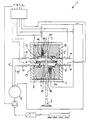
- the invention is based on an embodiment shown schematically in the drawing described.
- a valve control 1 for internal combustion engines includes one electro-magnetic actuator 2 with gas springs 3 and 4, one with a gas exchange valve 5 armature 6 in drive connection between a closing magnet 7 and an opening magnet 8 against restoring forces of the gas springs 3 and 4 is arranged oscillating.
- the gas springs 3 and 4 is made of a rechargeable Storage 9 metered a gas via controllable valves 10 by means of lines 9 ′, 9 ′′, being gas from the gas springs 3 and 4 via controllable drain valves 11 is drained.
- the armature 6 is arranged as a slidably movable in a cylinder 12 of the actuator 2 Separating piston 13 is formed between the two gas springs 3 and 4, and that the metering valves 10 and the drain valves 11 depending on Load ranges of the internal combustion engine controlled by the adjustment of adapted spring characteristics serve, the respective gas spring 3, 4 beyond the limiting End face 7 'or 8' of the closing magnet 7 or the opening magnet 8 with a controlled / regulated volume variable chamber 14 in the respective magnet 7, 8 in Connection is established.
- each chamber 14 includes a pressure controlled against a return spring 15 displaceable piston 16, via its A corresponding compression end pressure between the separating piston measures the displacement 13 or armature 12 and the respective end face 7 'or 8' of the closing magnet 7 or the opening magnet 8 is effected.
- the chambers 14 can be controlled separately or together be what, for example, with separate control of the chambers 14 in the Gas springs 3 and 4 different spring characteristics can be realized.
Landscapes
- Engineering & Computer Science (AREA)
- Mechanical Engineering (AREA)
- General Engineering & Computer Science (AREA)
- Valve Device For Special Equipments (AREA)
- Magnetically Actuated Valves (AREA)
- Output Control And Ontrol Of Special Type Engine (AREA)
Abstract
Description
Claims (4)
- Ventilsteuerung für Brennkraftmaschinen mit einem mit Gasfedern ausgerüsteten elektro-magnetischen Aktor,dadurch gekennzeichnet,bei dem ein mit einem Gaswechselventil (5) in Antriebsverbindung stehender Anker (6) zwischen einem Schließmagneten (7) und einem Öffnungsmagneten (8) gegen Rückstellkräfte der Gasfedern (3, 4) oszillierend angeordnet ist, wobeiden mittels des Ankers (6) voneinander getrennten Gasfedern (3, 4) aus einem aufladbaren Speicher (9) ein Gas über ansteuerbare Ventile (10) zugemessen undaus den Gasfedern (3, 4) über ansteuerbare Ablass-Ventile (11) Gas abgelassen ist,dass der Anker (6) als ein in einem Zylinder (12) des Aktors (2) gleitbeweglich dicht angeordneter Trennkolben (13) zwischen beiden Gasfedern (3, 4) ausgebildet ist, unddass die Zumess-Ventile (10) und die Ablass-Ventile (11) in Abhängigkeit von Lastbereichen der Brennkraftmaschine gesteuert der Einstellung angepasster Federkennlinien dienen, wobeidie jeweilige Gasfeder (3, 4) jenseits der begrenzenden Stirnseite (7', 8') des Schließmagneten (7) bzw. des Öffnungsmagneten (8) mit einer gesteuert/geregelt volumenvariablen Kammer (14) im jeweiligen Magneten (7, 8) in Verbindung steht.
- Ventilsteuerung nach Anspruch 1, dadurch gekennzeichnet,dass jede Kammer (14) einen druckgesteuert gegen eine Rückstellfeder (15) verschiebbaren Kolben (16) umfasst, überdessen Maß der Verschiebung ein entsprechender Verdichtungsenddruck zwischen Trennkolben (13) bzw. Anker (6) und der jeweiligen Stirnseite (7', 8') des Schließmagneten (7) und des Öffnungsmagneten (8) bewirkt ist.
- Ventilsteuerung nach Anspruch 1 und 2, dadurch gekennzeichnet,dass über die Kammer (14) im Schließmagneten (7) mittels eines druckgesteuert beschleunigten Kolbens (16) beim Start der Brennkraftmaschine eine Gasverdrängung bewirkt ist zum Trennen eines in Schließstellung des Gaswechselventils (5) mittels eines Dauermagneten (17) an der Stirnseite (7') des Schließmagneten (7) gehaltenen Trennkolbens (13) bzw. Ankers (6), derbeim Abstellen der Brennkraftmaschine druckgesteuert in dieser Schließstellung angeordnet ist.
- Ventilsteuerung nach den Ansprüchen 1 bis 3, dadurch gekennzeichnet, dass die Kammern (14) jeweils gesondert und/oder gemeinsam angesteuert sind.
Applications Claiming Priority (2)
| Application Number | Priority Date | Filing Date | Title |
|---|---|---|---|
| DE10003115 | 2000-01-26 | ||
| DE10003115A DE10003115A1 (de) | 2000-01-26 | 2000-01-26 | Ventilsteuerung für Brennkraftmaschinen mit einem mit Gasfedern ausgerüsteten elektro-magnetischen Aktor |
Publications (3)
| Publication Number | Publication Date |
|---|---|
| EP1120549A2 true EP1120549A2 (de) | 2001-08-01 |
| EP1120549A3 EP1120549A3 (de) | 2001-12-05 |
| EP1120549B1 EP1120549B1 (de) | 2005-05-25 |
Family
ID=7628665
Family Applications (1)
| Application Number | Title | Priority Date | Filing Date |
|---|---|---|---|
| EP00126374A Expired - Lifetime EP1120549B1 (de) | 2000-01-26 | 2000-12-02 | Ventilsteuerung für Brennkraftmaschinen mit einem mit Gasfedern ausgerüsteten elektro-magnetischen Aktor |
Country Status (3)
| Country | Link |
|---|---|
| EP (1) | EP1120549B1 (de) |
| DE (2) | DE10003115A1 (de) |
| ES (1) | ES2239995T3 (de) |
Cited By (3)
| Publication number | Priority date | Publication date | Assignee | Title |
|---|---|---|---|---|
| GB2382378A (en) * | 2001-11-22 | 2003-05-28 | Keith Gordon Hall | Electromagnetic and gas pressure valve actuation |
| EP1357265A3 (de) * | 2002-04-22 | 2004-01-02 | Toyota Jidosha Kabushiki Kaisha | Elektromagnetischer Ventiltriebmechanismus |
| WO2004044390A1 (en) * | 2002-11-12 | 2004-05-27 | Duckdive Pty. Limited | High speed solenoid valve |
Citations (1)
| Publication number | Priority date | Publication date | Assignee | Title |
|---|---|---|---|---|
| US5611303A (en) | 1995-01-11 | 1997-03-18 | Toyota Jidosha Kabushiki Kaisha | Valve operating apparatus of internal combustion engine |
Family Cites Families (4)
| Publication number | Priority date | Publication date | Assignee | Title |
|---|---|---|---|---|
| DE19725218C2 (de) * | 1997-06-15 | 2000-11-02 | Daimler Chrysler Ag | Vorrichtung zur Betätigung eines Gaswechselventiles für eine Brennkraftmaschine |
| DE19733186A1 (de) * | 1997-07-31 | 1999-02-04 | Fev Motorentech Gmbh & Co Kg | Elektromagnetisch betätigbares Gaswechselventil für eine Kolbenbrennkraftmaschine |
| DE19829858A1 (de) * | 1998-07-05 | 2000-01-13 | Bayerische Motoren Werke Ag | Kombinierter elektromagnetischer/pneumatischer Aktuator zur Steuerung eines Hubventils, insbesondere Gaswechselventil einer Brennkraftmaschine |
| JP2000027616A (ja) * | 1998-07-10 | 2000-01-25 | Nissan Motor Co Ltd | 内燃機関の動弁装置 |
-
2000
- 2000-01-26 DE DE10003115A patent/DE10003115A1/de not_active Withdrawn
- 2000-12-02 ES ES00126374T patent/ES2239995T3/es not_active Expired - Lifetime
- 2000-12-02 DE DE50010392T patent/DE50010392D1/de not_active Expired - Fee Related
- 2000-12-02 EP EP00126374A patent/EP1120549B1/de not_active Expired - Lifetime
Patent Citations (1)
| Publication number | Priority date | Publication date | Assignee | Title |
|---|---|---|---|---|
| US5611303A (en) | 1995-01-11 | 1997-03-18 | Toyota Jidosha Kabushiki Kaisha | Valve operating apparatus of internal combustion engine |
Cited By (4)
| Publication number | Priority date | Publication date | Assignee | Title |
|---|---|---|---|---|
| GB2382378A (en) * | 2001-11-22 | 2003-05-28 | Keith Gordon Hall | Electromagnetic and gas pressure valve actuation |
| GB2382378B (en) * | 2001-11-22 | 2003-12-24 | Keith Gordon Hall | Electromagnetic valve actuator |
| EP1357265A3 (de) * | 2002-04-22 | 2004-01-02 | Toyota Jidosha Kabushiki Kaisha | Elektromagnetischer Ventiltriebmechanismus |
| WO2004044390A1 (en) * | 2002-11-12 | 2004-05-27 | Duckdive Pty. Limited | High speed solenoid valve |
Also Published As
| Publication number | Publication date |
|---|---|
| DE50010392D1 (de) | 2005-06-30 |
| EP1120549A3 (de) | 2001-12-05 |
| DE10003115A1 (de) | 2001-08-02 |
| EP1120549B1 (de) | 2005-05-25 |
| ES2239995T3 (es) | 2005-10-16 |
Similar Documents
| Publication | Publication Date | Title |
|---|---|---|
| DE10062999C5 (de) | Regelbarer Schwingungsdämpfer mit einer Dämpfungskraftsteuerung | |
| DE69109951T2 (de) | Ventilstellglied mit hydraulischem Antrieb und pneumatischem Rücklauf. | |
| EP0196438A2 (de) | Ventilsteuervorrichtung für eine Hubkolben-Brennkraftmaschine | |
| DE102018107763A1 (de) | Magnetventil | |
| DE1550577B2 (de) | Druckmittelbetätigtes Absperrventil mit einer Dämpfungseinrichtung | |
| DE4440289C2 (de) | Motorbremsvorrichtung | |
| DE69120736T2 (de) | Stellglied mit Rückführung durch Energierückgewinnung | |
| DE68911286T2 (de) | Pneumatisches Stellglied. | |
| EP1974131B1 (de) | Gaswechselventilbetätigungsvorrichtung | |
| DE102009027214A1 (de) | Kraftstoffeinspritzgerät | |
| EP1120549A2 (de) | Ventilsteuerung für Brennkraftmaschinen mit einem mit Gasfedern ausgerüsteten elektro-magnetichen Aktor | |
| EP1631746A1 (de) | Hydraulischer antrieb zum verlagern eines stellgliedes | |
| DE29804549U1 (de) | Elektromagnetisch betätigbares Gaswechselventil für eine Kolbenbrennkraftmaschine mit pneumatischen Rückstellfedern | |
| DE2260198A1 (de) | Hydropneumatische aufhaengeeinheit eines motorfahrzeugaufhaengungssystems | |
| DE29704758U1 (de) | Hydraulische Schalteinheit | |
| DE19755276A1 (de) | Elektromagnetischer Aktuator zur Steuerung eines Gaswechselventils einer Brennkraftmaschine | |
| DE102008033766A1 (de) | Einrichtung zur variablen hydraulischen Ansteuerung von Gaswechselventilen | |
| DE102008041384A1 (de) | Vorrichtung zur Versorgung einer Verbrennungskraftmaschine mit Treibstoff | |
| EP1120548B1 (de) | Ventilsteuerung für Brennkraftmaschinen mit einem mit Gasfedern ausgerüsteten elektro-magnetischen Aktor | |
| DE10117401A1 (de) | Kraftstoffeinspritzsystem für eine Brennkraftmaschine | |
| DE19547187C2 (de) | Pneumatisch beaufschlagbare Hubkolbenmaschine | |
| DE19946842C2 (de) | Hochdruckpumpe | |
| DE102016214231B4 (de) | Verbindungseinheit als Teil der Aufhängung eines Verbrennungsmotors in der Karosserie eines Kraftfahrzeugs | |
| EP1120550B1 (de) | Ventilsteuerung für Brennkraftmaschinen mit einem mit Gasfedern ausgerüsteten elektro-magnetischen Aktor | |
| DE102017222202A1 (de) | Kraftstofffördereinrichtung für kryogene Kraftstoffe |
Legal Events
| Date | Code | Title | Description |
|---|---|---|---|
| PUAI | Public reference made under article 153(3) epc to a published international application that has entered the european phase |
Free format text: ORIGINAL CODE: 0009012 |
|
| AK | Designated contracting states |
Kind code of ref document: A2 Designated state(s): AT BE CH CY DE DK ES FI FR GB GR IE IT LI LU MC NL PT SE TR Kind code of ref document: A2 Designated state(s): DE ES FR GB IT SE |
|
| AX | Request for extension of the european patent |
Free format text: AL;LT;LV;MK;RO;SI |
|
| PUAL | Search report despatched |
Free format text: ORIGINAL CODE: 0009013 |
|
| AK | Designated contracting states |
Kind code of ref document: A3 Designated state(s): AT BE CH CY DE DK ES FI FR GB GR IE IT LI LU MC NL PT SE TR |
|
| AX | Request for extension of the european patent |
Free format text: AL;LT;LV;MK;RO;SI |
|
| 17P | Request for examination filed |
Effective date: 20020514 |
|
| AKX | Designation fees paid |
Free format text: DE ES FR GB IT SE |
|
| GRAP | Despatch of communication of intention to grant a patent |
Free format text: ORIGINAL CODE: EPIDOSNIGR1 |
|
| GRAS | Grant fee paid |
Free format text: ORIGINAL CODE: EPIDOSNIGR3 |
|
| GRAA | (expected) grant |
Free format text: ORIGINAL CODE: 0009210 |
|
| AK | Designated contracting states |
Kind code of ref document: B1 Designated state(s): DE ES FR GB IT SE |
|
| REG | Reference to a national code |
Ref country code: GB Ref legal event code: FG4D Free format text: NOT ENGLISH |
|
| GBT | Gb: translation of ep patent filed (gb section 77(6)(a)/1977) |
Effective date: 20050525 |
|
| REG | Reference to a national code |
Ref country code: IE Ref legal event code: FG4D Free format text: LANGUAGE OF EP DOCUMENT: GERMAN |
|
| REF | Corresponds to: |
Ref document number: 50010392 Country of ref document: DE Date of ref document: 20050630 Kind code of ref document: P |
|
| REG | Reference to a national code |
Ref country code: SE Ref legal event code: TRGR |
|
| REG | Reference to a national code |
Ref country code: ES Ref legal event code: FG2A Ref document number: 2239995 Country of ref document: ES Kind code of ref document: T3 |
|
| PGFP | Annual fee paid to national office [announced via postgrant information from national office to epo] |
Ref country code: DE Payment date: 20060131 Year of fee payment: 6 |
|
| ET | Fr: translation filed | ||
| PLBE | No opposition filed within time limit |
Free format text: ORIGINAL CODE: 0009261 |
|
| STAA | Information on the status of an ep patent application or granted ep patent |
Free format text: STATUS: NO OPPOSITION FILED WITHIN TIME LIMIT |
|
| 26N | No opposition filed |
Effective date: 20060228 |
|
| PGFP | Annual fee paid to national office [announced via postgrant information from national office to epo] |
Ref country code: ES Payment date: 20061123 Year of fee payment: 7 |
|
| PGFP | Annual fee paid to national office [announced via postgrant information from national office to epo] |
Ref country code: SE Payment date: 20061206 Year of fee payment: 7 |
|
| PGFP | Annual fee paid to national office [announced via postgrant information from national office to epo] |
Ref country code: GB Payment date: 20061221 Year of fee payment: 7 |
|
| PGFP | Annual fee paid to national office [announced via postgrant information from national office to epo] |
Ref country code: IT Payment date: 20061231 Year of fee payment: 7 |
|
| PG25 | Lapsed in a contracting state [announced via postgrant information from national office to epo] |
Ref country code: DE Free format text: LAPSE BECAUSE OF NON-PAYMENT OF DUE FEES Effective date: 20070703 |
|
| PGFP | Annual fee paid to national office [announced via postgrant information from national office to epo] |
Ref country code: FR Payment date: 20061228 Year of fee payment: 7 |
|
| EUG | Se: european patent has lapsed | ||
| GBPC | Gb: european patent ceased through non-payment of renewal fee |
Effective date: 20071202 |
|
| PG25 | Lapsed in a contracting state [announced via postgrant information from national office to epo] |
Ref country code: SE Free format text: LAPSE BECAUSE OF NON-PAYMENT OF DUE FEES Effective date: 20071203 |
|
| REG | Reference to a national code |
Ref country code: FR Ref legal event code: ST Effective date: 20081020 |
|
| PG25 | Lapsed in a contracting state [announced via postgrant information from national office to epo] |
Ref country code: GB Free format text: LAPSE BECAUSE OF NON-PAYMENT OF DUE FEES Effective date: 20071202 |
|
| REG | Reference to a national code |
Ref country code: ES Ref legal event code: FD2A Effective date: 20071203 |
|
| PG25 | Lapsed in a contracting state [announced via postgrant information from national office to epo] |
Ref country code: FR Free format text: LAPSE BECAUSE OF NON-PAYMENT OF DUE FEES Effective date: 20071231 Ref country code: ES Free format text: LAPSE BECAUSE OF NON-PAYMENT OF DUE FEES Effective date: 20071203 |
|
| PG25 | Lapsed in a contracting state [announced via postgrant information from national office to epo] |
Ref country code: IT Free format text: LAPSE BECAUSE OF NON-PAYMENT OF DUE FEES Effective date: 20071202 |