EP1119092A2 - Kupplung eines Motors mit einem Generator - Google Patents
Kupplung eines Motors mit einem Generator Download PDFInfo
- Publication number
- EP1119092A2 EP1119092A2 EP01100560A EP01100560A EP1119092A2 EP 1119092 A2 EP1119092 A2 EP 1119092A2 EP 01100560 A EP01100560 A EP 01100560A EP 01100560 A EP01100560 A EP 01100560A EP 1119092 A2 EP1119092 A2 EP 1119092A2
- Authority
- EP
- European Patent Office
- Prior art keywords
- generator
- elastic
- motor
- housing
- internal combustion
- Prior art date
- Legal status (The legal status is an assumption and is not a legal conclusion. Google has not performed a legal analysis and makes no representation as to the accuracy of the status listed.)
- Granted
Links
Images


Classifications
-
- F—MECHANICAL ENGINEERING; LIGHTING; HEATING; WEAPONS; BLASTING
- F16—ENGINEERING ELEMENTS AND UNITS; GENERAL MEASURES FOR PRODUCING AND MAINTAINING EFFECTIVE FUNCTIONING OF MACHINES OR INSTALLATIONS; THERMAL INSULATION IN GENERAL
- F16F—SPRINGS; SHOCK-ABSORBERS; MEANS FOR DAMPING VIBRATION
- F16F15/00—Suppression of vibrations in systems; Means or arrangements for avoiding or reducing out-of-balance forces, e.g. due to motion
- F16F15/10—Suppression of vibrations in rotating systems by making use of members moving with the system
- F16F15/12—Suppression of vibrations in rotating systems by making use of members moving with the system using elastic members or friction-damping members, e.g. between a rotating shaft and a gyratory mass mounted thereon
- F16F15/121—Suppression of vibrations in rotating systems by making use of members moving with the system using elastic members or friction-damping members, e.g. between a rotating shaft and a gyratory mass mounted thereon using springs as elastic members, e.g. metallic springs
- F16F15/124—Elastomeric springs
-
- F—MECHANICAL ENGINEERING; LIGHTING; HEATING; WEAPONS; BLASTING
- F02—COMBUSTION ENGINES; HOT-GAS OR COMBUSTION-PRODUCT ENGINE PLANTS
- F02B—INTERNAL-COMBUSTION PISTON ENGINES; COMBUSTION ENGINES IN GENERAL
- F02B63/00—Adaptations of engines for driving pumps, hand-held tools or electric generators; Portable combinations of engines with engine-driven devices
- F02B63/04—Adaptations of engines for driving pumps, hand-held tools or electric generators; Portable combinations of engines with engine-driven devices for electric generators
-
- F—MECHANICAL ENGINEERING; LIGHTING; HEATING; WEAPONS; BLASTING
- F16—ENGINEERING ELEMENTS AND UNITS; GENERAL MEASURES FOR PRODUCING AND MAINTAINING EFFECTIVE FUNCTIONING OF MACHINES OR INSTALLATIONS; THERMAL INSULATION IN GENERAL
- F16F—SPRINGS; SHOCK-ABSORBERS; MEANS FOR DAMPING VIBRATION
- F16F1/00—Springs
- F16F1/36—Springs made of rubber or other material having high internal friction, e.g. thermoplastic elastomers
- F16F1/38—Springs made of rubber or other material having high internal friction, e.g. thermoplastic elastomers with a sleeve of elastic material between a rigid outer sleeve and a rigid inner sleeve or pin, i.e. bushing-type
- F16F1/393—Springs made of rubber or other material having high internal friction, e.g. thermoplastic elastomers with a sleeve of elastic material between a rigid outer sleeve and a rigid inner sleeve or pin, i.e. bushing-type with spherical or conical sleeves
-
- F—MECHANICAL ENGINEERING; LIGHTING; HEATING; WEAPONS; BLASTING
- F16—ENGINEERING ELEMENTS AND UNITS; GENERAL MEASURES FOR PRODUCING AND MAINTAINING EFFECTIVE FUNCTIONING OF MACHINES OR INSTALLATIONS; THERMAL INSULATION IN GENERAL
- F16F—SPRINGS; SHOCK-ABSORBERS; MEANS FOR DAMPING VIBRATION
- F16F3/00—Spring units consisting of several springs, e.g. for obtaining a desired spring characteristic
- F16F3/08—Spring units consisting of several springs, e.g. for obtaining a desired spring characteristic with springs made of a material having high internal friction, e.g. rubber
- F16F3/087—Units comprising several springs made of plastics or the like material
- F16F3/0873—Units comprising several springs made of plastics or the like material of the same material or the material not being specified
- F16F3/0876—Units comprising several springs made of plastics or the like material of the same material or the material not being specified and of the same shape
-
- H—ELECTRICITY
- H02—GENERATION; CONVERSION OR DISTRIBUTION OF ELECTRIC POWER
- H02K—DYNAMO-ELECTRIC MACHINES
- H02K5/00—Casings; Enclosures; Supports
- H02K5/24—Casings; Enclosures; Supports specially adapted for suppression or reduction of noise or vibrations
-
- H—ELECTRICITY
- H02—GENERATION; CONVERSION OR DISTRIBUTION OF ELECTRIC POWER
- H02K—DYNAMO-ELECTRIC MACHINES
- H02K7/00—Arrangements for handling mechanical energy structurally associated with dynamo-electric machines, e.g. structural association with mechanical driving motors or auxiliary dynamo-electric machines
- H02K7/18—Structural association of electric generators with mechanical driving motors, e.g. with turbines
- H02K7/1807—Rotary generators
- H02K7/1815—Rotary generators structurally associated with reciprocating piston engines
-
- F—MECHANICAL ENGINEERING; LIGHTING; HEATING; WEAPONS; BLASTING
- F02—COMBUSTION ENGINES; HOT-GAS OR COMBUSTION-PRODUCT ENGINE PLANTS
- F02B—INTERNAL-COMBUSTION PISTON ENGINES; COMBUSTION ENGINES IN GENERAL
- F02B63/00—Adaptations of engines for driving pumps, hand-held tools or electric generators; Portable combinations of engines with engine-driven devices
- F02B63/04—Adaptations of engines for driving pumps, hand-held tools or electric generators; Portable combinations of engines with engine-driven devices for electric generators
- F02B63/044—Adaptations of engines for driving pumps, hand-held tools or electric generators; Portable combinations of engines with engine-driven devices for electric generators the engine-generator unit being placed on a frame or in an housing
- F02B2063/045—Frames for generator-engine sets
-
- F—MECHANICAL ENGINEERING; LIGHTING; HEATING; WEAPONS; BLASTING
- F02—COMBUSTION ENGINES; HOT-GAS OR COMBUSTION-PRODUCT ENGINE PLANTS
- F02B—INTERNAL-COMBUSTION PISTON ENGINES; COMBUSTION ENGINES IN GENERAL
- F02B63/00—Adaptations of engines for driving pumps, hand-held tools or electric generators; Portable combinations of engines with engine-driven devices
- F02B63/04—Adaptations of engines for driving pumps, hand-held tools or electric generators; Portable combinations of engines with engine-driven devices for electric generators
- F02B63/042—Rotating electric generators
Definitions
- the invention relates to a motor-generator arrangement with an internal combustion engine, whose output shaft via an elastic coupling with the drive shaft of Generator is connected.
- Such motor-generator arrangements come as modules for, for example Combined heat and power plants are used.
- the elastic coupling allows torsional elasticity to compensate for torque surges and damping torsional vibrations and to achieve radial elasticity to compensate for shaft misalignments.
- the state of the art includes a solution as shown in Figure 1.
- the Output shaft 2 of the internal combustion engine 1 is connected to the via an elastic coupling 3 Drive shaft 4 of the generator 5 connected.
- the engine housing 6 of the internal combustion engine 1 is rigidly connected to the generator housing 8 of the connecting parts 7 Generator 5 connected.
- the entire motor-generator arrangement is elastic the floor 9 stored. This design ensures precise alignment of the internal combustion engine 1 to generator 5 not required.
- the disadvantage of this Variant however, the transmission of vibrations via the rigid intermediate parts, which can affect the generator 5 and ultimately destroy it.
- FIG. 3 A similar construction is shown in Figure 3, in which the internal combustion engine 1 and Generator 5 are attached to a common rigid frame 11, which rests elastically on the floor 9.
- a disadvantage of the variants according to Figures 2 and 3 is the fact that such Foundations or rigid frames for torque absorption are more complex to construct and are more expensive.
- the object of the invention is therefore to provide an improved motor-generator arrangement create that avoids the disadvantages of the prior art.
- this is achieved in that the motor housing of the internal combustion engine elastic, preferably rubber-elastic with the generator housing of the generator is connected.
- the required between the motor housing and generator housing Reliably transmit moments between the motor housing and generator housing, At the same time, however, vibration isolation between the internal combustion engine and generator, which protects the generator from engine vibrations remains.
- a rubber-elastic, flexible intermediate layer trained coupling can also be expensive common torque transmitting Avoid frames or foundations.
- a structurally preferred embodiment is that on the motor housing first ring flange arranged substantially around the output shaft is that on the generator housing a second, essentially around the drive shaft ring flange arranged around is attached, and that the two ring flanges are connected to one another via at least one elastic intermediate part, the elastic intermediate part advantageously a rubber-elastic elastomer layer having.
- the vibration decoupling between internal combustion engine and generator can basically but constructively in a variety of ways, preferably between Elastomer elements happen so that the vibrations from the engine to the Generator to be forwarded.
- constructions such as those for elastic shaft couplings are known per se (bolt couplings, Claw couplings, bead couplings, intermediate ring couplings, etc.)
- Figure 4 shows an embodiment of a motor arrangement according to the invention
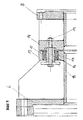
- Figure 5 shows a detail of the elastic coupling between the motor housing and the generator housing.
- the internal combustion engine drives 1 via the output shaft 2 to the drive shaft 4 of a generator 5.
- Both the internal combustion engine 1 and the generator 5 are simple rubber-supported pads 12 on the floor 9.
- a torsionally and radially elastic Coupling connects the output shaft 2 to the drive shaft 4.
- the motor housing 6 is elastic, preferably is elastically connected to the generator housing 8.
- a first ring flange 13 is arranged essentially around the output shaft 2.
- Around the generator housing 8 is essentially a second one around the drive shaft 4 Ring flange 14 arranged.
- Figure 5 shows this elastic, flexible coupling using a rubber-elastic elastomer layer 15 in detail.
- the elastomer layer 15 is applied to a steel core 16 and from a sleeve 17 surrounded.
- the flange 13 of the motor housing 6 and the flange 14 of the generator housing 8 are connected via the screw 18 to nut 19, the Screw 18 is elastically supported in the elastomer layer 15. All in all are several such elastically mounted screws over the circumference of the Flanges 13 and 14 distributed.
- the invention is of course not based on the illustrated embodiments limited. There are numerous design options for the invention to realize elastic coupling between the motor housing and generator housing. It is essential that this connection on the one hand must be able to to transmit the required torques and preferably an axis angle offset to keep it as small as possible, on the other hand, preferably using elastomeric materials, is designed such that they vibrate from the internal combustion engine not or only strongly attenuated to the generator, and protects it from damage caused by vibrations. An elaborate foundation or frame construction as used in the state of the art according to Figures 2 and 3 is provided can be avoided.
Abstract
Description
Bild 5 zeigt ein Detail der elastischen Kopplung zwischen Motorgehäuse und Generatorgehäuse.
Claims (3)
- Motor-Generator-Anordnung mit einem Verbrennungsmotor, dessen Abtriebswelle über eine elastische Kupplung mit der Antriebswelle des Generators verbunden ist, dadurch gekennzeichnet, daß das Motorgehäuse des Verbrennungsmotors elastisch, vorzugsweise gummielastisch mit dem Generatorgehäuse des Generators verbunden ist.
- Motor-Generator-Anordnung nach Anspruch 1, dadurch gekennzeichnet, daß am Motorgehäuse ein erster, im wesentlichen um die Abtriebswelle herum angeordneter Ringflansch angebracht ist, daß am Generatorgehäuse ein zweiter, im wesentlichen um die Antriebswelle herum angeordneter Ringflansch angebracht ist, und daß die beiden Ringflansche über zumindest einen elastischen Zwischenteil miteinander verbunden sind.
- Motor-Generator-Anordnung nach Anspruch 2, dadurch gekennzeichnet, daß der elastische Zwischenteil eine gummielastische Elastomerschicht aufweist.
Priority Applications (1)
| Application Number | Priority Date | Filing Date | Title |
|---|---|---|---|
| AT01100560T ATE291288T1 (de) | 2000-01-19 | 2001-01-10 | Kupplung eines motors mit einem generator |
Applications Claiming Priority (2)
| Application Number | Priority Date | Filing Date | Title |
|---|---|---|---|
| AT0008000A AT410019B (de) | 2000-01-19 | 2000-01-19 | Motor-generator-anordnung |
| AT802000 | 2000-01-19 |
Publications (3)
| Publication Number | Publication Date |
|---|---|
| EP1119092A2 true EP1119092A2 (de) | 2001-07-25 |
| EP1119092A3 EP1119092A3 (de) | 2003-12-10 |
| EP1119092B1 EP1119092B1 (de) | 2005-03-16 |
Family
ID=3601692
Family Applications (1)
| Application Number | Title | Priority Date | Filing Date |
|---|---|---|---|
| EP01100560A Expired - Lifetime EP1119092B1 (de) | 2000-01-19 | 2001-01-10 | Kupplung eines Motors mit einem Generator |
Country Status (6)
| Country | Link |
|---|---|
| US (1) | US6869367B2 (de) |
| EP (1) | EP1119092B1 (de) |
| AT (2) | AT410019B (de) |
| DE (1) | DE50105578D1 (de) |
| DK (1) | DK1119092T3 (de) |
| ES (1) | ES2237498T3 (de) |
Cited By (4)
| Publication number | Priority date | Publication date | Assignee | Title |
|---|---|---|---|---|
| CN105292137A (zh) * | 2015-10-29 | 2016-02-03 | 南车资阳机车有限公司 | 一种内燃机车柴油发电机组安装结构 |
| WO2018065657A1 (en) * | 2016-10-05 | 2018-04-12 | Wärtsilä Finland Oy | Engine-generator set |
| WO2018092098A1 (en) * | 2016-11-18 | 2018-05-24 | Cummins Power Generation Limited | Generator set integrated gearbox |
| US10934931B2 (en) | 2018-06-22 | 2021-03-02 | Cummins Power Generation Limited | Integrated epicyclic gearbox and alternator |
Families Citing this family (10)
| Publication number | Priority date | Publication date | Assignee | Title |
|---|---|---|---|---|
| DE50208431D1 (de) * | 2001-08-30 | 2006-11-23 | Siemens Ag | Schockfeste elektrische schiffsmaschine, z.b. motor oder generator |
| DE102004044292A1 (de) * | 2004-09-10 | 2006-03-30 | Centa-Antriebe Kirschey Gmbh | Vorrichtung zur Übertragung von Drehmomenten |
| US20090323256A1 (en) | 2008-06-25 | 2009-12-31 | Errera Michael R | Interface for system for generating electric power |
| US8307801B2 (en) * | 2008-09-30 | 2012-11-13 | Caterpillar Inc. | Combination to support and rotatably drive mass |
| AT510834B1 (de) | 2010-11-25 | 2012-09-15 | Avl List Gmbh | Stromerzeugungsvorrichtung, insbesondere range extender für ein kraftfahrzeug |
| WO2013067134A1 (en) | 2011-11-01 | 2013-05-10 | Cummins Power Generation, Inc. | Modular skid base |
| CN105916461B (zh) | 2014-01-31 | 2020-02-18 | 柯惠Lp公司 | 用于手术系统的接口 |
| AU2017269374B2 (en) | 2016-05-26 | 2021-07-08 | Covidien Lp | Instrument drive units |
| WO2017205481A1 (en) | 2016-05-26 | 2017-11-30 | Covidien Lp | Robotic surgical assemblies and instrument drive units thereof |
| US11272992B2 (en) | 2016-06-03 | 2022-03-15 | Covidien Lp | Robotic surgical assemblies and instrument drive units thereof |
Citations (1)
| Publication number | Priority date | Publication date | Assignee | Title |
|---|---|---|---|---|
| DE3334429A1 (de) * | 1983-09-23 | 1985-04-11 | Lindenberg Aggregate GmbH, 5064 Rösrath | Verbrennungsmotor mit generator zur stromerzeugung |
Family Cites Families (17)
| Publication number | Priority date | Publication date | Assignee | Title |
|---|---|---|---|---|
| US1522612A (en) * | 1921-01-14 | 1925-01-13 | Simplex Utilities Corp | Automatically-controlled generator |
| US1972441A (en) * | 1932-07-11 | 1934-09-04 | Siemens Ag | Internal combustion engine electric generating set |
| US2928961A (en) * | 1956-01-18 | 1960-03-15 | Wayne J Morrill | Pump motor mounting |
| DE1119997B (de) * | 1960-05-02 | 1961-12-21 | Licentia Gmbh | Schwingungsisolierender Einbau von Elektromotoren |
| US3622821A (en) * | 1970-03-27 | 1971-11-23 | Black & Decker Mfg Co | Double-insulated motor armature |
| US3893775A (en) * | 1974-05-13 | 1975-07-08 | Gen Tire & Rubber Co | Resilient bushing with long fatigue life |
| US4425813A (en) * | 1981-06-04 | 1984-01-17 | Wadensten Theodore S | Vibration dampening apparatus for motor actuated eccentric forces |
| DE3206837A1 (de) * | 1982-02-26 | 1983-09-15 | Getrag Getriebe- Und Zahnradfabrik Gmbh, 7140 Ludwigsburg | Verbrennungsmotor und getriebe umfassende anordnung |
| JPS6140425A (ja) * | 1984-07-31 | 1986-02-26 | Yanmar Diesel Engine Co Ltd | ケ−ス収容型エンジン発電機 |
| US4648579A (en) * | 1985-06-10 | 1987-03-10 | Wilson John D | Cushioned mounting arrangement for a motor housing |
| SE466967B (sv) * | 1987-02-09 | 1992-05-04 | Volvo Penta Ab | Baedd foer motorer med tillsatsaggregat |
| US4866294A (en) * | 1987-07-31 | 1989-09-12 | United Technologies Electro Systems Inc. | Double insulated starter motor |
| US4819503A (en) * | 1987-12-22 | 1989-04-11 | Unites States Of America As Represented By The Secretay Of The Navy | Low frequency structureborne vibration isolation mount |
| US5126607A (en) * | 1991-03-22 | 1992-06-30 | Ncr Corporation | Stepper motor vibration isolator |
| DE4234920A1 (de) * | 1992-10-16 | 1994-04-21 | Audi Ag | Zweiteiliges Flanschlager |
| US5354182A (en) * | 1993-05-17 | 1994-10-11 | Vickers, Incorporated | Unitary electric-motor/hydraulic-pump assembly with noise reduction features |
| DE19545922A1 (de) * | 1995-12-08 | 1997-09-18 | Magnet Motor Gmbh | Motorfahrzeug |
-
2000
- 2000-01-19 AT AT0008000A patent/AT410019B/de not_active IP Right Cessation
-
2001
- 2001-01-10 ES ES01100560T patent/ES2237498T3/es not_active Expired - Lifetime
- 2001-01-10 DK DK01100560T patent/DK1119092T3/da active
- 2001-01-10 AT AT01100560T patent/ATE291288T1/de not_active IP Right Cessation
- 2001-01-10 EP EP01100560A patent/EP1119092B1/de not_active Expired - Lifetime
- 2001-01-10 DE DE50105578T patent/DE50105578D1/de not_active Expired - Lifetime
- 2001-01-19 US US09/765,518 patent/US6869367B2/en not_active Expired - Lifetime
Patent Citations (1)
| Publication number | Priority date | Publication date | Assignee | Title |
|---|---|---|---|---|
| DE3334429A1 (de) * | 1983-09-23 | 1985-04-11 | Lindenberg Aggregate GmbH, 5064 Rösrath | Verbrennungsmotor mit generator zur stromerzeugung |
Cited By (5)
| Publication number | Priority date | Publication date | Assignee | Title |
|---|---|---|---|---|
| CN105292137A (zh) * | 2015-10-29 | 2016-02-03 | 南车资阳机车有限公司 | 一种内燃机车柴油发电机组安装结构 |
| WO2018065657A1 (en) * | 2016-10-05 | 2018-04-12 | Wärtsilä Finland Oy | Engine-generator set |
| WO2018092098A1 (en) * | 2016-11-18 | 2018-05-24 | Cummins Power Generation Limited | Generator set integrated gearbox |
| US10608503B2 (en) | 2016-11-18 | 2020-03-31 | Cummins Power Generation Limited | Generator set integrated gearbox |
| US10934931B2 (en) | 2018-06-22 | 2021-03-02 | Cummins Power Generation Limited | Integrated epicyclic gearbox and alternator |
Also Published As
| Publication number | Publication date |
|---|---|
| ATA802000A (de) | 2002-05-15 |
| AT410019B (de) | 2003-01-27 |
| US6869367B2 (en) | 2005-03-22 |
| DK1119092T3 (da) | 2005-05-23 |
| ES2237498T3 (es) | 2005-08-01 |
| DE50105578D1 (de) | 2005-04-21 |
| EP1119092A3 (de) | 2003-12-10 |
| EP1119092B1 (de) | 2005-03-16 |
| US20010008343A1 (en) | 2001-07-19 |
| ATE291288T1 (de) | 2005-04-15 |
Similar Documents
| Publication | Publication Date | Title |
|---|---|---|
| EP1119092B1 (de) | Kupplung eines Motors mit einem Generator | |
| DE3009349C2 (de) | Rotor-Wellen-Anordnung mit Inversionsmöglichkeit des Rotors beim Auftreten einer starken Unwucht | |
| EP1940667B1 (de) | Kardanische doppelgelenkkupplung für schienenfahrzeuge | |
| EP2323771B1 (de) | Schwerlastantriebsanordnung und damit angetriebene mühle | |
| DE102011010191B4 (de) | Anordnung mit einem Tilger zur Tilgung von torsionalen Schwingungen einer Welle | |
| DE102014014490A1 (de) | Kupplungsvorrichtung | |
| DE2752979A1 (de) | Getriebe fuer ein winkelwerkzeug, insbesondere winkelschleifer | |
| CH648102A5 (de) | Abzweiggetriebe fuer einen schiffsantrieb. | |
| DE102010006363B4 (de) | Umwuchtoptimierter Gelenkwellentilger | |
| EP1196699A1 (de) | Leistungsverzweigungsgetriebe | |
| DE19729046C2 (de) | Schiffsantrieb mit einer Antriebsmaschine und direkt angetriebener Propellerwelle | |
| DE2630506A1 (de) | Elastische wellenkupplung | |
| EP2664536B1 (de) | Schiffsantriebsystem | |
| DE102010024619B4 (de) | Vorgespanntes Differentialgetriebe ohne Zahnflankenwechsel | |
| DE3516903A1 (de) | Schiffsgetriebe | |
| DE60003093T2 (de) | Kupplung für Pumpe und Motor | |
| DE4345126C1 (de) | Schiffsantriebseinrichtung | |
| DE19832933B4 (de) | Antriebszahnritzel für einen Zahnkranz/Ritzel-Antrieb | |
| DE1530034A1 (de) | Einzelachsantrieb fuer ein elektrisches Triebfahrzeug | |
| WO2019206369A1 (de) | Hybridmodul, verfahren zur montage des hybridmoduls und antriebsanordnung | |
| DE2936403B2 (de) | Prüfmaschine für drehelastische Kupplungen | |
| DE19830862C2 (de) | Planetengetriebe mit Ausgleichskupplung | |
| DE3720557A1 (de) | Einrichtung zur daempfung von schwingungen im antriebsstrang eines kraftfahrzeugs | |
| DE4412394C1 (de) | In einem Gehäuse elastisch gelagertes Antriebsmittel | |
| DE2409856A1 (de) | Elektromechanischer antrieb, insbesondere stellantrieb, getriebemotor oder dergleichen |
Legal Events
| Date | Code | Title | Description |
|---|---|---|---|
| PUAI | Public reference made under article 153(3) epc to a published international application that has entered the european phase |
Free format text: ORIGINAL CODE: 0009012 |
|
| AK | Designated contracting states |
Kind code of ref document: A2 Designated state(s): AT BE CH CY DE DK ES FI FR GB GR IE IT LI LU MC NL PT SE TR |
|
| AX | Request for extension of the european patent |
Free format text: AL;LT;LV;MK;RO;SI |
|
| PUAL | Search report despatched |
Free format text: ORIGINAL CODE: 0009013 |
|
| AK | Designated contracting states |
Kind code of ref document: A3 Designated state(s): AT BE CH CY DE DK ES FI FR GB GR IE IT LI LU MC NL PT SE TR |
|
| AX | Request for extension of the european patent |
Extension state: AL LT LV MK RO SI |
|
| RIC1 | Information provided on ipc code assigned before grant |
Ipc: 7F 02B 63/04 B Ipc: 7F 16D 3/64 B Ipc: 7H 02K 7/18 A |
|
| 17P | Request for examination filed |
Effective date: 20040415 |
|
| GRAP | Despatch of communication of intention to grant a patent |
Free format text: ORIGINAL CODE: EPIDOSNIGR1 |
|
| AKX | Designation fees paid |
Designated state(s): AT BE CH CY DE DK ES FI FR GB GR IE IT LI LU MC NL PT SE TR |
|
| GRAS | Grant fee paid |
Free format text: ORIGINAL CODE: EPIDOSNIGR3 |
|
| GRAA | (expected) grant |
Free format text: ORIGINAL CODE: 0009210 |
|
| AK | Designated contracting states |
Kind code of ref document: B1 Designated state(s): AT BE CH CY DE DK ES FI FR GB GR IE IT LI LU MC NL PT SE TR |
|
| PG25 | Lapsed in a contracting state [announced via postgrant information from national office to epo] |
Ref country code: IE Free format text: LAPSE BECAUSE OF FAILURE TO SUBMIT A TRANSLATION OF THE DESCRIPTION OR TO PAY THE FEE WITHIN THE PRESCRIBED TIME-LIMIT Effective date: 20050316 |
|
| REG | Reference to a national code |
Ref country code: GB Ref legal event code: FG4D Free format text: NOT ENGLISH |
|
| REG | Reference to a national code |
Ref country code: CH Ref legal event code: EP |
|
| REG | Reference to a national code |
Ref country code: IE Ref legal event code: FG4D Free format text: GERMAN |
|
| REF | Corresponds to: |
Ref document number: 50105578 Country of ref document: DE Date of ref document: 20050421 Kind code of ref document: P |
|
| REG | Reference to a national code |
Ref country code: DK Ref legal event code: T3 |
|
| REG | Reference to a national code |
Ref country code: SE Ref legal event code: TRGR |
|
| GBT | Gb: translation of ep patent filed (gb section 77(6)(a)/1977) |
Effective date: 20050518 |
|
| PG25 | Lapsed in a contracting state [announced via postgrant information from national office to epo] |
Ref country code: GR Free format text: LAPSE BECAUSE OF FAILURE TO SUBMIT A TRANSLATION OF THE DESCRIPTION OR TO PAY THE FEE WITHIN THE PRESCRIBED TIME-LIMIT Effective date: 20050616 |
|
| REG | Reference to a national code |
Ref country code: ES Ref legal event code: FG2A Ref document number: 2237498 Country of ref document: ES Kind code of ref document: T3 |
|
| PG25 | Lapsed in a contracting state [announced via postgrant information from national office to epo] |
Ref country code: PT Free format text: LAPSE BECAUSE OF FAILURE TO SUBMIT A TRANSLATION OF THE DESCRIPTION OR TO PAY THE FEE WITHIN THE PRESCRIBED TIME-LIMIT Effective date: 20050907 |
|
| REG | Reference to a national code |
Ref country code: IE Ref legal event code: FD4D |
|
| PG25 | Lapsed in a contracting state [announced via postgrant information from national office to epo] |
Ref country code: AT Free format text: LAPSE BECAUSE OF NON-PAYMENT OF DUE FEES Effective date: 20060110 |
|
| PLBE | No opposition filed within time limit |
Free format text: ORIGINAL CODE: 0009261 |
|
| STAA | Information on the status of an ep patent application or granted ep patent |
Free format text: STATUS: NO OPPOSITION FILED WITHIN TIME LIMIT |
|
| PG25 | Lapsed in a contracting state [announced via postgrant information from national office to epo] |
Ref country code: CH Free format text: LAPSE BECAUSE OF NON-PAYMENT OF DUE FEES Effective date: 20060131 Ref country code: LI Free format text: LAPSE BECAUSE OF NON-PAYMENT OF DUE FEES Effective date: 20060131 Ref country code: LU Free format text: LAPSE BECAUSE OF NON-PAYMENT OF DUE FEES Effective date: 20060131 Ref country code: BE Free format text: LAPSE BECAUSE OF NON-PAYMENT OF DUE FEES Effective date: 20060131 Ref country code: MC Free format text: LAPSE BECAUSE OF NON-PAYMENT OF DUE FEES Effective date: 20060131 |
|
| ET | Fr: translation filed | ||
| 26N | No opposition filed |
Effective date: 20051219 |
|
| REG | Reference to a national code |
Ref country code: CH Ref legal event code: PL |
|
| BERE | Be: lapsed |
Owner name: JENBACHER A.G. Effective date: 20060131 |
|
| PG25 | Lapsed in a contracting state [announced via postgrant information from national office to epo] |
Ref country code: TR Free format text: LAPSE BECAUSE OF FAILURE TO SUBMIT A TRANSLATION OF THE DESCRIPTION OR TO PAY THE FEE WITHIN THE PRESCRIBED TIME-LIMIT Effective date: 20050316 |
|
| PG25 | Lapsed in a contracting state [announced via postgrant information from national office to epo] |
Ref country code: CY Free format text: LAPSE BECAUSE OF FAILURE TO SUBMIT A TRANSLATION OF THE DESCRIPTION OR TO PAY THE FEE WITHIN THE PRESCRIBED TIME-LIMIT Effective date: 20050316 |
|
| REG | Reference to a national code |
Ref country code: FR Ref legal event code: PLFP Year of fee payment: 16 |
|
| PGFP | Annual fee paid to national office [announced via postgrant information from national office to epo] |
Ref country code: DK Payment date: 20160125 Year of fee payment: 16 |
|
| REG | Reference to a national code |
Ref country code: FR Ref legal event code: PLFP Year of fee payment: 17 |
|
| REG | Reference to a national code |
Ref country code: DK Ref legal event code: EBP Effective date: 20170131 |
|
| REG | Reference to a national code |
Ref country code: FR Ref legal event code: PLFP Year of fee payment: 18 |
|
| PG25 | Lapsed in a contracting state [announced via postgrant information from national office to epo] |
Ref country code: DK Free format text: LAPSE BECAUSE OF NON-PAYMENT OF DUE FEES Effective date: 20170131 |
|
| PGFP | Annual fee paid to national office [announced via postgrant information from national office to epo] |
Ref country code: SE Payment date: 20181221 Year of fee payment: 19 |
|
| PGFP | Annual fee paid to national office [announced via postgrant information from national office to epo] |
Ref country code: NL Payment date: 20191227 Year of fee payment: 20 Ref country code: FI Payment date: 20191223 Year of fee payment: 20 |
|
| PGFP | Annual fee paid to national office [announced via postgrant information from national office to epo] |
Ref country code: FR Payment date: 20191219 Year of fee payment: 20 |
|
| PGFP | Annual fee paid to national office [announced via postgrant information from national office to epo] |
Ref country code: DE Payment date: 20191218 Year of fee payment: 20 Ref country code: IT Payment date: 20200102 Year of fee payment: 20 Ref country code: GB Payment date: 20191224 Year of fee payment: 20 Ref country code: ES Payment date: 20200203 Year of fee payment: 20 |
|
| REG | Reference to a national code |
Ref country code: SE Ref legal event code: EUG |
|
| REG | Reference to a national code |
Ref country code: SE Ref legal event code: EUG |
|
| PG25 | Lapsed in a contracting state [announced via postgrant information from national office to epo] |
Ref country code: SE Free format text: LAPSE BECAUSE OF NON-PAYMENT OF DUE FEES Effective date: 20200111 |
|
| REG | Reference to a national code |
Ref country code: DE Ref legal event code: R071 Ref document number: 50105578 Country of ref document: DE |
|
| REG | Reference to a national code |
Ref country code: NL Ref legal event code: MK Effective date: 20210109 |
|
| REG | Reference to a national code |
Ref country code: GB Ref legal event code: PE20 Expiry date: 20210109 |
|
| REG | Reference to a national code |
Ref country code: FI Ref legal event code: MAE |
|
| REG | Reference to a national code |
Ref country code: ES Ref legal event code: FD2A Effective date: 20210426 |
|
| PG25 | Lapsed in a contracting state [announced via postgrant information from national office to epo] |
Ref country code: GB Free format text: LAPSE BECAUSE OF EXPIRATION OF PROTECTION Effective date: 20210109 |
|
| PG25 | Lapsed in a contracting state [announced via postgrant information from national office to epo] |
Ref country code: ES Free format text: LAPSE BECAUSE OF EXPIRATION OF PROTECTION Effective date: 20210111 |