EP1118252B1 - Lighting control system including a wireless remote sensor - Google Patents
Lighting control system including a wireless remote sensor Download PDFInfo
- Publication number
- EP1118252B1 EP1118252B1 EP00948011A EP00948011A EP1118252B1 EP 1118252 B1 EP1118252 B1 EP 1118252B1 EP 00948011 A EP00948011 A EP 00948011A EP 00948011 A EP00948011 A EP 00948011A EP 1118252 B1 EP1118252 B1 EP 1118252B1
- Authority
- EP
- European Patent Office
- Prior art keywords
- sensor
- light
- wireless
- control unit
- light source
- Prior art date
- Legal status (The legal status is an assumption and is not a legal conclusion. Google has not performed a legal analysis and makes no representation as to the accuracy of the status listed.)
- Expired - Lifetime
Links
- 230000033001 locomotion Effects 0.000 claims description 10
- 238000005516 engineering process Methods 0.000 claims description 9
- 230000005540 biological transmission Effects 0.000 claims description 7
- 230000005670 electromagnetic radiation Effects 0.000 claims description 3
- 238000009434 installation Methods 0.000 description 8
- 238000000034 method Methods 0.000 description 7
- 238000005286 illumination Methods 0.000 description 5
- 238000003306 harvesting Methods 0.000 description 4
- 230000008569 process Effects 0.000 description 4
- 238000004891 communication Methods 0.000 description 3
- 238000003384 imaging method Methods 0.000 description 3
- 230000006872 improvement Effects 0.000 description 3
- 230000010354 integration Effects 0.000 description 3
- 238000007906 compression Methods 0.000 description 2
- 230000006835 compression Effects 0.000 description 2
- 238000013461 design Methods 0.000 description 2
- 238000010586 diagram Methods 0.000 description 2
- 230000003287 optical effect Effects 0.000 description 2
- 238000012545 processing Methods 0.000 description 2
- 230000003416 augmentation Effects 0.000 description 1
- 230000001413 cellular effect Effects 0.000 description 1
- 230000027288 circadian rhythm Effects 0.000 description 1
- 238000013144 data compression Methods 0.000 description 1
- 238000001514 detection method Methods 0.000 description 1
- 238000005553 drilling Methods 0.000 description 1
- 230000009977 dual effect Effects 0.000 description 1
- 230000000694 effects Effects 0.000 description 1
- 230000007613 environmental effect Effects 0.000 description 1
- 238000002955 isolation Methods 0.000 description 1
- 238000012423 maintenance Methods 0.000 description 1
- 238000012986 modification Methods 0.000 description 1
- 230000004048 modification Effects 0.000 description 1
- 230000037361 pathway Effects 0.000 description 1
- 230000035479 physiological effects, processes and functions Effects 0.000 description 1
- 230000008707 rearrangement Effects 0.000 description 1
- 230000009467 reduction Effects 0.000 description 1
Images

Classifications
-
- H—ELECTRICITY
- H05—ELECTRIC TECHNIQUES NOT OTHERWISE PROVIDED FOR
- H05B—ELECTRIC HEATING; ELECTRIC LIGHT SOURCES NOT OTHERWISE PROVIDED FOR; CIRCUIT ARRANGEMENTS FOR ELECTRIC LIGHT SOURCES, IN GENERAL
- H05B41/00—Circuit arrangements or apparatus for igniting or operating discharge lamps
- H05B41/14—Circuit arrangements
- H05B41/36—Controlling
- H05B41/38—Controlling the intensity of light
- H05B41/39—Controlling the intensity of light continuously
- H05B41/392—Controlling the intensity of light continuously using semiconductor devices, e.g. thyristor
- H05B41/3921—Controlling the intensity of light continuously using semiconductor devices, e.g. thyristor with possibility of light intensity variations
- H05B41/3922—Controlling the intensity of light continuously using semiconductor devices, e.g. thyristor with possibility of light intensity variations and measurement of the incident light
-
- H—ELECTRICITY
- H05—ELECTRIC TECHNIQUES NOT OTHERWISE PROVIDED FOR
- H05B—ELECTRIC HEATING; ELECTRIC LIGHT SOURCES NOT OTHERWISE PROVIDED FOR; CIRCUIT ARRANGEMENTS FOR ELECTRIC LIGHT SOURCES, IN GENERAL
- H05B47/00—Circuit arrangements for operating light sources in general, i.e. where the type of light source is not relevant
- H05B47/10—Controlling the light source
- H05B47/17—Operational modes, e.g. switching from manual to automatic mode or prohibiting specific operations
-
- H—ELECTRICITY
- H05—ELECTRIC TECHNIQUES NOT OTHERWISE PROVIDED FOR
- H05B—ELECTRIC HEATING; ELECTRIC LIGHT SOURCES NOT OTHERWISE PROVIDED FOR; CIRCUIT ARRANGEMENTS FOR ELECTRIC LIGHT SOURCES, IN GENERAL
- H05B47/00—Circuit arrangements for operating light sources in general, i.e. where the type of light source is not relevant
- H05B47/10—Controlling the light source
- H05B47/175—Controlling the light source by remote control
- H05B47/19—Controlling the light source by remote control via wireless transmission
- H05B47/195—Controlling the light source by remote control via wireless transmission the transmission using visible or infrared light
-
- Y—GENERAL TAGGING OF NEW TECHNOLOGICAL DEVELOPMENTS; GENERAL TAGGING OF CROSS-SECTIONAL TECHNOLOGIES SPANNING OVER SEVERAL SECTIONS OF THE IPC; TECHNICAL SUBJECTS COVERED BY FORMER USPC CROSS-REFERENCE ART COLLECTIONS [XRACs] AND DIGESTS
- Y10—TECHNICAL SUBJECTS COVERED BY FORMER USPC
- Y10S—TECHNICAL SUBJECTS COVERED BY FORMER USPC CROSS-REFERENCE ART COLLECTIONS [XRACs] AND DIGESTS
- Y10S315/00—Electric lamp and discharge devices: systems
- Y10S315/04—Dimming circuit for fluorescent lamps
Definitions
- the present invention pertains generally to the field of lighting control. More particularly, the present invention relates to a lighting control system including a wireless, integrated circuit, sensor for detecting light and/or occupancy in an area.
- fluorescent lamps offer large energy savings as compared to incandescent lamps. Additional energy savings can be obtained through the use of dimmable fluorescent lamp ballasts. These ballasts can be controlled by ballast control circuitry which reduces the level of the light produced by the fluorescent lamp. In this regard, conservation of energy is always an economic and environmental consideration in designing lighting systems.
- the level and type of background illumination has a profound effect on the optimum artificial light needed for a work area.
- the light level in an area also affects the human physiology. It is well accepted that lighting can dramatically affect the circadian rhythm of the human physiological system. Accordingly, it is desirable to control the level of the artificial light to provide an optimum amount of light, see, e.g ., US-A- 5,648 656, US-A-5 459 376 and US-A-5 237 169 the contents of which are incorporated herein by reference.
- Lighting systems are known that control, i.e. , decrease or increase, the level of artificial light in relation to the level of daylight in an area.
- these conventional lighting control systems are hampered by the lack of adequate light sensors for flexible daylight harvesting applications.
- conventional sensor technology uses a single photodiode that senses the light on a work surface so that the light can be adjusted accordingly to maintain a constant value during the day.
- separate motion sensors may also be used to detect the movement of an occupant in an area, as described in U.S. Patent 5,489,827, the contents of which are incorporated herein by reference.
- a light source is turned “on” or “off” depending on the presence, or lack thereof, of an occupant in the sensing area.
- determining the state of occupancy within an area can be difficult depending on the positioning of the motion sensor.
- the motion sensor's field of view may be limited or obstructed.
- subsequent rearrangement of an area's contents e.g. , finiture may impair the field of view.
- Some improvement in lighting control technology has been achieved by using multiple light sensors.
- the sensors are tied to a control unit that generates a control signal based on the inputs from the multiple sensors.
- a ballast dimming signal based on some algorithm of multiple sensor inputs to control a light source is known.
- This type of arrangement results in complex installation/setup procedures and expensive equipment requirements.
- this arrangement fails to address the shortcomings of conventional sensor technology discussed above.
- a lighting control system in one aspect of the present invention, includes a light source having a control unit and a wireless receiver.
- the system also includes a sensor having a plurality of pixels and a wireless transmitter, which are formed by a single integrated circuit (IC).
- the sensor transmits data to the light source using the wireless transmitter so that the control unit can control the light source in accordance with the transmitted data.
- EP 0872817 discloses an alarm device equipped with a sensor, a light source and a wireless transmitter for communicating the state that the alarm device is in to a mobile control unit. It be also mentioned that US 4,065,644 discloses a switching system for establishing a number of simultaneous but independent communication links between selected lines comprising an array of photosensors each connected to a different communication line.
- One advantageous embodiment of the present invention relates to the use of CMOS imaging technology for the sensor.
- This embodiment enables the integration of multiple functions into one integrated circuit (IC). This results in greatly reduced power requirements as compared to conventional sensors.
- the IC sensor architecture combines a wireless interface, as well as a pixel array for improved daylight harvesting and occupancy detection. The integration of these multiple functions into a single integrated component results in significant cost savings and reduced (installation/equipment) complexity for the lighting control system and sensor.
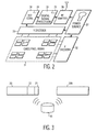
- an area such as a room 10 (a portion of which is shown) includes a luminaire, such as a lamp fixture 20, a sensor 30, a work surface 40, an occupant 50, and a remote control unit 60.
- a luminaire such as a lamp fixture 20, a sensor 30, a work surface 40, an occupant 50, and a remote control unit 60.
- the present invention of course is not limited to the office environment shown in Fig. 1, but may be used in any domestic environment or surrounding, such as buildings, sporting stadiums, aircraft or ships.
- the lamp fixture 20 may be any controllable light source, such as a dimmable fluorescent lamp.
- the sensor 30 is a standalone device that detects simultaneously illumination from various directions and surfaces in the room 10. This is done to obtain improved control and balance of the light level in the room 10 as compared to conventional lighting control methods that depend on sensing the light level using a single or multiple photodiode sensors.
- the sensor 30 preferably comprises a CMOS pixel (imaging) array 31.
- the present invention is not limited to CMOS technology. Other types of low power dissipating logic technology may be used.
- the sensor 30 also comprises X-decoder 32, Y-decoder 33, A/D converter 34, digital signal processor (DSP) 35, wireless transmitter 36 and a power source 37.
- the pixel array 31 is arranged in rows (x-axis) and columns (y-axis). Of course, other pixel configurations are possible.
- X-decoder 32 and Y-decoder 33 are used to select a respective pixel from the array 31.
- the A/D converter 34 converts the analog data from a respective pixel to digital data in a manner well known in the art.
- the DSP 35 processes the digital data for transmission by the wireless transmitter 36.
- CMOS image sensors allow for integration of complex signal processing electronics on a single IC. This allow CMOS image sensors to have similar resolution while greatly reducing the power requirements as compared to CCD's.
- CMOS image sensors may have resolutions of tens to hundreds of thousands of pixels (primarily used for video and camera applications). But the preferred resolution results in significant size and cost advantages for the sensor 30. Moreover, as compared to conventional photodiode sensors which offer a resolution of one pixel, the sensor 30's resolution provides considerable improvement in the ability to sense illumination from various directions and surfaces in the room 10.
- This resolution enables the sensor 30 to differentiate simultaneously light from various directions and sources in the room 10. This light may originate from, or be reflected from different sources or surfaces in the area. For example, as shown in Fig. 1, the sensor 30 detects light 11, 12 and 13 from the work surface 40, as well as from windows ( i.e. , daylight) and wall surfaces around the room 10 (i.e., background or ambient light). This information is collected by the sensor 30 so that an optimum level of artificial lighting for daylight harvesting can be determined as discussed below. Secondly, this resolution also allows the pixel array 31 of the sensor 30 to detect movement of the occupants in the room so that the sensor 30 can also be used as an occupancy detector.
- the senor 30 collects data in each pixel of the pixel array 31. This data is then converted into digital form by the A/D converter 34. The digital data is then processed/analyzed by the DSP 35 to extract key information, such as objects in motion, light levels from various sources and identification of specific features. This information is then formatted by the DSP 35 for transmission by the wireless transmitter 36.
- the sensor 30 can be automatically calibrated through a digital circuit 38, e.g., included in the A/D converter 34, to eliminate analog errors such as drift and offset.
- the digital circuit 38 can also be programmed to adapt the sensor 30 to different environments and lighting conditions, resulting in rapid and trouble-free installation.
- the sensor 30 may have a plurality of predetermined environment settings and operational modes such as:
- Night-On a mode in which the lamp fixture 20 is automatically turn on when no daylight is detected or falls below a predetermined threshold level.
- the lamp fixture 20 includes a wireless interface 21 and a control unit 22.
- the information transmitted by the sensor 30 is received by the wireless interface 21.
- the control unit 22 then processes the information to derive the correct control information (e.g ., reduction or augmentation of the light output) based on the room lighting levels and/or the presence of occupants.
- control unit 22 may include ballast control hardware and a microprocessor for executing such algorithms and functions.
- the control unit 22 also processes the information received from the sensor 30 to interpret information transmitted by the sensor 30 in accordance with the various predetermined settings and modes. It is also understood that the environment and mode settings are not necessarily mutually exclusive. Different environment and mode settings may be used together to tailor the lighting control system as needed.
- the information transmitted by the sensor is preferably in a compressed digital format.
- Various compression formats may be used as will be appreciated by one skilled in the art. Compression reduces the transmission power consumption of the sensor 30.
- the information is preferably transmitted at low data rate because such transmission can be performed reliably and using low-power.
- the peak transmission data rate is in the range of 10Kbits/second or less.
- the sensor 30 addresses the problem of wiring costs by incorporating the wireless transmitter 36.
- CMOS passive or active RF transmitters are known in the art and have been used for applications such as identification badges.
- the wireless transmitter 36 is a low-power RF transmitter.
- a short range RF transmitter can operate reliably at a power level of one milliwatt or less.
- the low duty cycle can reduce the average RF power level to less than 100 microwatts.
- This type of RF transmitter will provide a short-range link (1-2 meters) between the sensor 30 and the lamp fixture 20.
- other types of wireless interfaces may be used rather than RF, such as IR or ultrasonic interfaces.
- the senor 30 When using a low-power RF transmitter, the sensor 30 is placed in close proximity to the control unit 22. For example, by mounting the sensor 30 to the ceiling near the lamp fixture 20. The wireless communications link is then automatically established. No wiring or drilling holes in the ceiling is required. Moreover, system setup is quick and easy.
- the senor 30 is used to control only its neighbor lamp fixture 20. This allows for easy control of individual lighting in cellular light arrangements. In lighting fixtures in large office rooms, for example, this makes it possible to achieve good daylight harvesting by allowing the fixtures near the windows to respond separately from fixtures that are further removed from the windows. It also permits personalized light setting by the occupant 50, who may wish to control the illumination on the work surface differently when working on the computer or drafting a memorandum.
- the senor 30 may incorporate identification codes as part of each transmitted information packet. Other control/selection information can also be transmitted in the information packet.
- the control unit 22 of the lamp fixture 20 only accepts information packets with a particular code. This enables the sensor 30 to control multiple lamp fixtures within an area individually. For example, as shown in Fig. 3, a second lamp fixture 20A also receives and decodes the transmission from the sensor 30.
- the wireless interface to the lamp fixture 20 also results in design improvements and advantages in the control unit 22.
- a CMOS receiver can be easily integrated into a small low-cost IC, perhaps even as part of a main microcontroller IC of the lamp fixture 20 or control unit 22. Only access to a small and inexpensive antenna structure is needed.
- the senor 30 includes circuitry for a wireless receiver 39 (shown in Fig. 2). While a separate circuit block for the wireless receiver 39 may be used, it is preferable that the DSP 35 include this functionality.
- the wireless receiver 39 preferably functions as an infrared (IR) detector so that the lamp fixture 20 can be controlled using the handheld or wall mounted remote control unit 60. The use and popularity of these types of remote control units are increasing.
- the DSP 35 can filter the IR signals from other optical signals detected by the pixel array 31.
- the pixel array 31 can detect both white light and IR signals with efficiency, so that a separate IR photo-detector deceive is not needed.
- IR signals modulate at a high frequency (e.g ., 36 kHz from a typical television remote control device) and are digitally encoded.
- the DSP 35 can filter and decode this IR signal from slower varying white light signals.
- Information based on the infrared signals from the remote control unit 60 is combined with other information that is transmitted to the control unit 22 by the sensor 30.
- the wireless interface eliminates the need for wiring and reduces installation costs, particularly for retrofit installations.
- the senor 30 functions as a passive device, or at least operates without a power-source such as batteries or a connection to an external power source.
- a power-source such as batteries or a connection to an external power source.
- This can be achieved through the use of low-power CMOS circuit techniques.
- CMOS circuit techniques By performing the signal processing and data compression (discussed above) on the sensor 30, and using a low-power transmitter only for short periods of time, results in very low IC power requirements, e.g., power levels of less than a 100 microwatts. Since, the power requirements are so low, the sensor 30 can maintain operation via the power source 37 (shown in Fig. 2) using only electromagnetic radiation, i.e., "free" power, which emanates from ambient energy sources. For example, the free power can be obtained from either ambient light, or RF energy from a nearby ballast of the lamp fixture 20.
- the senor 30 may received "free” power from ambient energy sources and also include a battery backup.
- the power source 37 provides power to the sensor 30 to operate using the “free” power and/or the battery supplied power. This allows the sensor 30 to conserve the battery energy level by using the "free” power when possible.
Landscapes
- Engineering & Computer Science (AREA)
- Computer Networks & Wireless Communication (AREA)
- Circuit Arrangement For Electric Light Sources In General (AREA)
Applications Claiming Priority (3)
| Application Number | Priority Date | Filing Date | Title |
|---|---|---|---|
| US371374 | 1999-08-10 | ||
| US09/371,374 US6340864B1 (en) | 1999-08-10 | 1999-08-10 | Lighting control system including a wireless remote sensor |
| PCT/EP2000/007301 WO2001011926A1 (en) | 1999-08-10 | 2000-07-28 | Lighting control system including a wireless remote sensor |
Publications (2)
| Publication Number | Publication Date |
|---|---|
| EP1118252A1 EP1118252A1 (en) | 2001-07-25 |
| EP1118252B1 true EP1118252B1 (en) | 2003-10-01 |
Family
ID=23463732
Family Applications (1)
| Application Number | Title | Priority Date | Filing Date |
|---|---|---|---|
| EP00948011A Expired - Lifetime EP1118252B1 (en) | 1999-08-10 | 2000-07-28 | Lighting control system including a wireless remote sensor |
Country Status (6)
| Country | Link |
|---|---|
| US (1) | US6340864B1 (enExample) |
| EP (1) | EP1118252B1 (enExample) |
| JP (1) | JP5079196B2 (enExample) |
| CN (1) | CN1237850C (enExample) |
| DE (1) | DE60005637T2 (enExample) |
| WO (1) | WO2001011926A1 (enExample) |
Cited By (3)
| Publication number | Priority date | Publication date | Assignee | Title |
|---|---|---|---|---|
| DE102010003804A1 (de) * | 2010-04-09 | 2011-10-13 | Zumtobel Lighting Gmbh | Multifunktionale Sensoreinheit zum Ermitteln von Kontrollinformationen für die Lichtsteuerung |
| EP2914067A1 (en) | 2014-02-27 | 2015-09-02 | Airbus Operations GmbH | Lighting system and method for controlling a lighting system |
| DE102008036992B4 (de) | 2008-07-21 | 2024-05-23 | Abb Ag | System und Verfahren zum Regeln der Helligkeit in einem Raum |
Families Citing this family (142)
| Publication number | Priority date | Publication date | Assignee | Title |
|---|---|---|---|---|
| JP2001094887A (ja) * | 1999-09-21 | 2001-04-06 | Nikon Corp | 撮像装置および電子カメラ |
| EP1297725A1 (en) * | 2000-06-23 | 2003-04-02 | Koninklijke Philips Electronics N.V. | Lighting control device and method of controlling lighting using ccd sensor |
| US6636005B2 (en) * | 2001-11-14 | 2003-10-21 | Koninklijke Philips Eletronics N.V. | Architecture of ballast with integrated RF interface |
| US7081693B2 (en) * | 2002-03-07 | 2006-07-25 | Microstrain, Inc. | Energy harvesting for wireless sensor operation and data transmission |
| US20040044709A1 (en) * | 2002-09-03 | 2004-03-04 | Florencio Cabrera | System and method for optical data communication |
| US7111952B2 (en) * | 2003-03-24 | 2006-09-26 | Lutron Electronics Co., Inc. | System to control daylight and artificial illumination and sun glare in a space |
| US20040217718A1 (en) * | 2003-05-02 | 2004-11-04 | Russikesh Kumar | Digital addressable electronic ballast and control unit |
| WO2005005930A1 (en) * | 2003-07-09 | 2005-01-20 | Koninklijke Philips Electronics N.V. | Integrated senor |
| US7557433B2 (en) | 2004-10-25 | 2009-07-07 | Mccain Joseph H | Microelectronic device with integrated energy source |
| DE602005008551D1 (de) * | 2004-01-12 | 2008-09-11 | Koninkl Philips Electronics Nv | Beleuchtungssteuerung mit belegungsdetektion |
| EP1741317A1 (en) * | 2004-04-15 | 2007-01-10 | Koninklijke Philips Electronics N.V. | Mains wire antenna for wireless interface applications |
| WO2005107337A1 (en) * | 2004-05-05 | 2005-11-10 | Koninklijke Philips Electronics N.V. | Lighting device with user interface for light control |
| US20050259424A1 (en) * | 2004-05-18 | 2005-11-24 | Zampini Thomas L Ii | Collimating and controlling light produced by light emitting diodes |
| US20060067546A1 (en) * | 2004-09-27 | 2006-03-30 | Kimberly-Clark Worldwide, Inc. | Device for encouraging hand wash compliance |
| US20060067545A1 (en) * | 2004-09-27 | 2006-03-30 | Kimberly-Clark Worldwide, Inc. | Device for encouraging hand wash compliance |
| DE102004047962A1 (de) * | 2004-10-01 | 2006-04-06 | Patent-Treuhand-Gesellschaft für elektrische Glühlampen mbH | Sensorsystem |
| DE102005008996B4 (de) * | 2005-01-21 | 2014-02-13 | Tridonic Gmbh & Co Kg | Verfahren und Vorrichtung zum Einstellen eines kontinuierlichen Dimmbetriebes oder eines Dimmbetriebes mit nur zwei Pegeln |
| US7400911B2 (en) * | 2005-01-31 | 2008-07-15 | Eaton Corporation | Wireless node and method of powering a wireless node employing ambient light to charge an energy store |
| US7127935B2 (en) * | 2005-02-07 | 2006-10-31 | Honeywell International Inc. | Wireless gas composition sensor system |
| JP4645260B2 (ja) * | 2005-03-28 | 2011-03-09 | パナソニック電工株式会社 | 照明器具、照明システムおよび放電灯の寿命判定方法 |
| TW200643824A (en) * | 2005-04-12 | 2006-12-16 | Koninkl Philips Electronics Nv | Pattern based occupancy sensing system and method |
| ATE545320T1 (de) * | 2005-09-12 | 2012-02-15 | Acuity Brands Inc | Lichtverwaltungssystem mit vernetztem intelligenten beleuchtungsvorrichtungs-managern und anwendungen dafür |
| EP1946282A4 (en) | 2005-10-05 | 2011-12-28 | Abl Ip Holding Llc | METHOD AND SYSTEM FOR REMOTELY MONITORING AND CONTROLLING FIELD DEVICES USING A SAFE NETWORK SUPPORTED BY REVERBER |
| KR20080080352A (ko) * | 2005-11-30 | 2008-09-03 | 코닌클리즈케 필립스 일렉트로닉스 엔.브이. | 광원으로부터 충전되는 제어 장치, 제어 장치 충전 방법,제어 장치 충전 시스템, 원격 센서, 원격 센서 충전 방법,원격 센서 충전 시스템 |
| FR2899057B1 (fr) * | 2006-03-22 | 2008-05-23 | Lyracom Sarl | Procede de gestion d'un reseau d'eclairage et dispositif associe |
| US8203445B2 (en) * | 2006-03-28 | 2012-06-19 | Wireless Environment, Llc | Wireless lighting |
| US8669716B2 (en) | 2007-08-30 | 2014-03-11 | Wireless Environment, Llc | Wireless light bulb |
| US9860965B2 (en) | 2006-03-28 | 2018-01-02 | Wireless Environment, Llc | Cloud connected lighting system |
| US9338839B2 (en) | 2006-03-28 | 2016-05-10 | Wireless Environment, Llc | Off-grid LED power failure lights |
| US8994276B2 (en) | 2006-03-28 | 2015-03-31 | Wireless Environment, Llc | Grid shifting system for a lighting circuit |
| US8519566B2 (en) | 2006-03-28 | 2013-08-27 | Wireless Environment, Llc | Remote switch sensing in lighting devices |
| US11523488B1 (en) | 2006-03-28 | 2022-12-06 | Amazon Technologies, Inc. | Wirelessly controllable communication module |
| US9074736B2 (en) | 2006-03-28 | 2015-07-07 | Wireless Environment, Llc | Power outage detector and transmitter |
| US7766511B2 (en) * | 2006-04-24 | 2010-08-03 | Integrated Illumination Systems | LED light fixture |
| US20080086680A1 (en) * | 2006-05-27 | 2008-04-10 | Beckman Christopher V | Techniques of document annotation according to subsequent citation |
| US8914865B2 (en) * | 2006-05-27 | 2014-12-16 | Loughton Technology, L.L.C. | Data storage and access facilitating techniques |
| US7999415B2 (en) | 2007-05-29 | 2011-08-16 | Christopher Vance Beckman | Electronic leakage reduction techniques |
| US7859539B2 (en) | 2006-05-27 | 2010-12-28 | Christopher Vance Beckman | Organizational viewing techniques |
| WO2008000086A1 (en) * | 2006-06-30 | 2008-01-03 | Fibro Light Technology Inc. | Integrated sensor and light level adjustment apparatus for 'daylight harvesting' |
| JP2010503177A (ja) * | 2006-09-11 | 2010-01-28 | コムライト エーエス | 公共照明の制御の装置、システムおよび方法 |
| US7812543B2 (en) * | 2006-11-15 | 2010-10-12 | Budike Jr Lothar E S | Modular wireless lighting control system using a common ballast control interface |
| US7729941B2 (en) | 2006-11-17 | 2010-06-01 | Integrated Illumination Systems, Inc. | Apparatus and method of using lighting systems to enhance brand recognition |
| US7859398B2 (en) * | 2006-12-13 | 2010-12-28 | Eaton Corporation | System and method for maintaining and controlling a plurality of wireless light fixtures |
| US8013538B2 (en) | 2007-01-26 | 2011-09-06 | Integrated Illumination Systems, Inc. | TRI-light |
| US8190301B2 (en) | 2008-02-19 | 2012-05-29 | Genea Energy Partners, Inc. | Building optimization system and lighting switch with adaptive blind, window and air quality controls |
| JP4900046B2 (ja) * | 2007-03-21 | 2012-03-21 | パナソニック電工株式会社 | ワイヤレス送信機およびワイヤレス受信機 |
| WO2009023965A1 (en) * | 2007-08-21 | 2009-02-26 | William Wiener | Interactive appliances, appliance systems and appliance control methods, and controls therefor |
| US8742686B2 (en) * | 2007-09-24 | 2014-06-03 | Integrated Illumination Systems, Inc. | Systems and methods for providing an OEM level networked lighting system |
| WO2009044354A2 (en) * | 2007-10-04 | 2009-04-09 | Philips Intellectual Property & Standards Gmbh | Light-sensing device for informing light-generating device |
| TWI353736B (en) * | 2007-11-23 | 2011-12-01 | Compal Communications Inc | Device of wireless remote control and operating me |
| CN101499307B (zh) * | 2008-01-31 | 2011-03-16 | 建兴电子科技股份有限公司 | 光盘刻录机及写入卷标于光盘片上的方法 |
| US20090200951A1 (en) * | 2008-02-08 | 2009-08-13 | Purespectrum, Inc. | Methods and Apparatus for Dimming Light Sources |
| US20090200952A1 (en) * | 2008-02-08 | 2009-08-13 | Purespectrum, Inc. | Methods and apparatus for dimming light sources |
| US8594976B2 (en) | 2008-02-27 | 2013-11-26 | Abl Ip Holding Llc | System and method for streetlight monitoring diagnostics |
| CN102037616B (zh) | 2008-03-20 | 2014-05-07 | 美国航易明国际有限公司 | 电导磁耦合系统 |
| US8915609B1 (en) | 2008-03-20 | 2014-12-23 | Cooper Technologies Company | Systems, methods, and devices for providing a track light and portable light |
| US8022843B2 (en) * | 2008-03-31 | 2011-09-20 | The Boeing Company | Wireless aircraft sensor network |
| US8274383B2 (en) * | 2008-03-31 | 2012-09-25 | The Boeing Company | Methods and systems for sensing activity using energy harvesting devices |
| CN101999252A (zh) * | 2008-04-02 | 2011-03-30 | 基因能源伙伴公司 | 具有自适应遮光帘、窗和空气质量控制器的建筑物最优化系统和照明开关 |
| EP2277055A1 (en) * | 2008-04-28 | 2011-01-26 | BUDIKE, Lothar E.S., Jr. | Multi configurable lighting and energy control system and modules |
| US8255487B2 (en) * | 2008-05-16 | 2012-08-28 | Integrated Illumination Systems, Inc. | Systems and methods for communicating in a lighting network |
| WO2009150562A1 (en) * | 2008-06-11 | 2009-12-17 | Koninklijke Philips Electronics N.V. | Wireless sensor device and illumination system comprising such a device |
| US8575846B2 (en) | 2008-07-23 | 2013-11-05 | Koninklijke Philips N.V. | Illumination system with automatic adaptation to daylight level |
| US9148937B2 (en) | 2008-09-03 | 2015-09-29 | Lutron Electronics Co., Inc. | Radio-frequency lighting control system with occupancy sensing |
| US8009042B2 (en) | 2008-09-03 | 2011-08-30 | Lutron Electronics Co., Inc. | Radio-frequency lighting control system with occupancy sensing |
| US9277629B2 (en) | 2008-09-03 | 2016-03-01 | Lutron Electronics Co., Inc. | Radio-frequency lighting control system with occupancy sensing |
| US8232909B2 (en) * | 2008-09-30 | 2012-07-31 | Cooper Technologies Company | Doppler radar motion detector for an outdoor light fixture |
| CA2957199C (en) | 2008-11-26 | 2019-01-08 | Wireless Environment, Llc | Wireless lighting devices and applications |
| US8098017B2 (en) * | 2009-01-22 | 2012-01-17 | Daniel William Chidester | Automatic, low level floor lighting system |
| US8328582B1 (en) | 2009-02-01 | 2012-12-11 | MagicLux, LLC | Shortened adapter for light bulb sockets with miniature remote controller |
| US8199010B2 (en) | 2009-02-13 | 2012-06-12 | Lutron Electronics Co., Inc. | Method and apparatus for configuring a wireless sensor |
| US20100237711A1 (en) * | 2009-03-18 | 2010-09-23 | Leviton Manufacturing Co., Inc. | Occupancy Sensing With Device Clock |
| US8081216B2 (en) * | 2009-03-26 | 2011-12-20 | Hong Kong Science and Technology Research Institute Co., Ltd. | Lighting control system and method |
| US8451116B2 (en) * | 2009-03-27 | 2013-05-28 | Lutron Electronics Co., Inc. | Wireless battery-powered daylight sensor |
| US20100244568A1 (en) * | 2009-03-31 | 2010-09-30 | Innovative Engineering & Product Development, Inc. | Lighting module with wireless alternating current detection system |
| US20100244569A1 (en) * | 2009-03-31 | 2010-09-30 | Innovative Engineering & Product Development, Inc. | Fluorescent form factor lighting module with wireless alternating current detection system |
| US20100245279A1 (en) * | 2009-03-31 | 2010-09-30 | Robe Lighting S.R.O. | Display and display control system for an automated luminaire |
| US8585245B2 (en) | 2009-04-23 | 2013-11-19 | Integrated Illumination Systems, Inc. | Systems and methods for sealing a lighting fixture |
| JP5572697B2 (ja) | 2009-05-01 | 2014-08-13 | コーニンクレッカ フィリップス エヌ ヴェ | 画像に基づく照明制御及びセキュリティ制御のためのシステム及び装置 |
| US8436542B2 (en) * | 2009-05-04 | 2013-05-07 | Hubbell Incorporated | Integrated lighting system and method |
| US20110148309A1 (en) * | 2009-12-23 | 2011-06-23 | Schneider Electric USA, Inc. | Occupancy sensor with embedded signaling capability |
| US20110148193A1 (en) * | 2009-12-23 | 2011-06-23 | Schneider Electric USA, Inc. | Networked occupancy sensor and power pack |
| US9345107B2 (en) * | 2010-02-11 | 2016-05-17 | Koninklijke Philips N.V. | Light level control for building illumination |
| TWI420967B (zh) * | 2010-05-11 | 2013-12-21 | Compal Communications Inc | 無線感測照明系統 |
| US8401231B2 (en) * | 2010-11-09 | 2013-03-19 | Biological Illumination, Llc | Sustainable outdoor lighting system for use in environmentally photo-sensitive area |
| US10564613B2 (en) | 2010-11-19 | 2020-02-18 | Hubbell Incorporated | Control system and method for managing wireless and wired components |
| US9429962B2 (en) * | 2010-11-19 | 2016-08-30 | Google Inc. | Auto-configuring time-of day for building control unit |
| US8436541B2 (en) | 2010-12-30 | 2013-05-07 | Schneider Electric USA, Inc. | Occupancy sensor with multi-level signaling |
| US9066381B2 (en) | 2011-03-16 | 2015-06-23 | Integrated Illumination Systems, Inc. | System and method for low level dimming |
| BR112013025377A2 (pt) * | 2011-04-04 | 2017-11-14 | Koninklijke Philips Nv | controlador, sistema e método de iluminação, configurado para estabelecer níveis de dimerização de uma pluralidade de fontes luminosas |
| US9967940B2 (en) | 2011-05-05 | 2018-05-08 | Integrated Illumination Systems, Inc. | Systems and methods for active thermal management |
| US11917740B2 (en) | 2011-07-26 | 2024-02-27 | Hunter Industries, Inc. | Systems and methods for providing power and data to devices |
| US9609720B2 (en) | 2011-07-26 | 2017-03-28 | Hunter Industries, Inc. | Systems and methods for providing power and data to lighting devices |
| US10874003B2 (en) | 2011-07-26 | 2020-12-22 | Hunter Industries, Inc. | Systems and methods for providing power and data to devices |
| US8710770B2 (en) | 2011-07-26 | 2014-04-29 | Hunter Industries, Inc. | Systems and methods for providing power and data to lighting devices |
| US20150237700A1 (en) | 2011-07-26 | 2015-08-20 | Hunter Industries, Inc. | Systems and methods to control color and brightness of lighting devices |
| US9521725B2 (en) | 2011-07-26 | 2016-12-13 | Hunter Industries, Inc. | Systems and methods for providing power and data to lighting devices |
| US8952626B2 (en) | 2011-08-18 | 2015-02-10 | Industrial Technology Research Institute | Lighting control systems and methods |
| GB2496623B (en) * | 2011-11-16 | 2013-11-06 | Wirefield Ltd | Transmitter receiver and wireless lighting system |
| US8749146B2 (en) | 2011-12-05 | 2014-06-10 | Mojo Labs, Inc. | Auto commissioning of light fixture using optical bursts |
| US8749145B2 (en) | 2011-12-05 | 2014-06-10 | Mojo Labs, Inc. | Determination of lighting contributions for light fixtures using optical bursts |
| US8842009B2 (en) | 2012-06-07 | 2014-09-23 | Mojo Labs, Inc. | Multiple light sensor multiple light fixture control |
| US8759847B2 (en) | 2011-12-22 | 2014-06-24 | Bridgelux, Inc. | White LED assembly with LED string and intermediate node substrate terminals |
| KR101332750B1 (ko) * | 2011-12-22 | 2013-11-28 | 김동한 | 패턴기반 감성조명 시스템 |
| GB2498570B (en) * | 2012-01-20 | 2016-02-17 | Cp Electronics Ltd | Battery-powered light level sensing device |
| BE1020514A3 (nl) | 2012-03-02 | 2013-12-03 | Econation | Lichtcontrolesysteem, lichtcontrolesysteemnetwerk of werkwijze voor het bedienen van het lichtcontrolesysteem of het lichtcontrolesysteemnetwerk. |
| US9320112B2 (en) | 2012-04-02 | 2016-04-19 | Kent Tabor | Control system for lighting assembly |
| ITVE20120014A1 (it) * | 2012-04-13 | 2013-10-14 | Teleco Automation Srl | Dispositivo di controllo della luminosita' in un ambiente.- |
| EP2654380A1 (en) * | 2012-04-18 | 2013-10-23 | ChengShih University of Science and Technology | Lamp with energy saving control |
| US8894437B2 (en) | 2012-07-19 | 2014-11-25 | Integrated Illumination Systems, Inc. | Systems and methods for connector enabling vertical removal |
| EP3297218B1 (en) | 2012-08-28 | 2020-10-21 | Delos Living, LLC | Environmental control system and method of operation such system |
| US20140125250A1 (en) | 2012-11-02 | 2014-05-08 | General Electric Company | Antenna sensor |
| US9379578B2 (en) | 2012-11-19 | 2016-06-28 | Integrated Illumination Systems, Inc. | Systems and methods for multi-state power management |
| US9420665B2 (en) | 2012-12-28 | 2016-08-16 | Integration Illumination Systems, Inc. | Systems and methods for continuous adjustment of reference signal to control chip |
| US9485814B2 (en) | 2013-01-04 | 2016-11-01 | Integrated Illumination Systems, Inc. | Systems and methods for a hysteresis based driver using a LED as a voltage reference |
| US9271375B2 (en) | 2013-02-25 | 2016-02-23 | Leviton Manufacturing Company, Inc. | System and method for occupancy sensing with enhanced functionality |
| EP2770804B1 (en) | 2013-02-26 | 2020-07-15 | Nxp B.V. | Lighting control method, computer program product and lighting control system |
| US9804024B2 (en) | 2013-03-14 | 2017-10-31 | Mojo Labs, Inc. | Light measurement and/or control translation for daylighting |
| WO2015039035A1 (en) | 2013-09-13 | 2015-03-19 | Cooper Technologies Company | System and method for auto-commissioning based on smart sensors |
| CN103763832A (zh) * | 2014-01-23 | 2014-04-30 | 龚飞 | 一种带有照度感应的灯光遥控器及其实现方法 |
| DE102014202720A1 (de) * | 2014-02-14 | 2015-08-20 | Ansorg Gmbh | Beleuchtungssystem |
| WO2015130786A1 (en) | 2014-02-28 | 2015-09-03 | Delos Living Llc | Systems, methods and articles for enhancing wellness associated with habitable environments |
| US10531545B2 (en) | 2014-08-11 | 2020-01-07 | RAB Lighting Inc. | Commissioning a configurable user control device for a lighting control system |
| US10085328B2 (en) | 2014-08-11 | 2018-09-25 | RAB Lighting Inc. | Wireless lighting control systems and methods |
| US9883567B2 (en) | 2014-08-11 | 2018-01-30 | RAB Lighting Inc. | Device indication and commissioning for a lighting control system |
| US10039174B2 (en) | 2014-08-11 | 2018-07-31 | RAB Lighting Inc. | Systems and methods for acknowledging broadcast messages in a wireless lighting control network |
| US10070496B2 (en) | 2015-03-30 | 2018-09-04 | Mojo Labs, Inc. | Task to wall color control |
| US10918030B2 (en) | 2015-05-26 | 2021-02-16 | Hunter Industries, Inc. | Decoder systems and methods for irrigation control |
| US10228711B2 (en) | 2015-05-26 | 2019-03-12 | Hunter Industries, Inc. | Decoder systems and methods for irrigation control |
| US10030844B2 (en) | 2015-05-29 | 2018-07-24 | Integrated Illumination Systems, Inc. | Systems, methods and apparatus for illumination using asymmetrical optics |
| US10060599B2 (en) | 2015-05-29 | 2018-08-28 | Integrated Illumination Systems, Inc. | Systems, methods and apparatus for programmable light fixtures |
| CN107852801B (zh) * | 2015-07-06 | 2020-01-24 | 飞利浦照明控股有限公司 | 无线联网照明系统和关联的设备及方法 |
| US10176563B2 (en) * | 2015-10-13 | 2019-01-08 | Sony Corporation | Mobile device, system and method |
| US9496894B1 (en) | 2015-10-21 | 2016-11-15 | GE Lighting Solutions, LLC | System and method for data compression over a communication network |
| US11668481B2 (en) | 2017-08-30 | 2023-06-06 | Delos Living Llc | Systems, methods and articles for assessing and/or improving health and well-being |
| WO2020049589A1 (en) * | 2018-09-03 | 2020-03-12 | Satish Kumar | Electronic device for controlling lighting |
| EP3850458A4 (en) | 2018-09-14 | 2022-06-08 | Delos Living, LLC | AIR CLEANING SYSTEMS AND PROCEDURES |
| US11844163B2 (en) | 2019-02-26 | 2023-12-12 | Delos Living Llc | Method and apparatus for lighting in an office environment |
| WO2020198183A1 (en) | 2019-03-25 | 2020-10-01 | Delos Living Llc | Systems and methods for acoustic monitoring |
| US10801714B1 (en) | 2019-10-03 | 2020-10-13 | CarJamz, Inc. | Lighting device |
| US12416908B2 (en) | 2022-12-29 | 2025-09-16 | Integrated Illumination Systems, Inc. | Systems and methods for manufacturing light fixtures |
| US12297996B2 (en) | 2023-02-16 | 2025-05-13 | Integrated Illumination Systems, Inc. | Cove light fixture with hidden integrated air return |
Family Cites Families (16)
| Publication number | Priority date | Publication date | Assignee | Title |
|---|---|---|---|---|
| US4065644A (en) | 1975-04-30 | 1977-12-27 | Shinosky Jr Leonard W | Electro-optical and electronic switching systems |
| US5181025A (en) * | 1991-05-24 | 1993-01-19 | The United States Of America As Represented By The Secretary Of The Air Force | Conformal telemetry system |
| FR2678752B1 (fr) | 1991-07-03 | 1993-10-29 | Somfy | Installation de commande du niveau d'eclairement d'un local. |
| EP0616302B1 (en) * | 1993-02-19 | 1999-06-23 | Mitsubishi Jukogyo Kabushiki Kaisha | Electronic traffic tariff reception system |
| US5841126A (en) | 1994-01-28 | 1998-11-24 | California Institute Of Technology | CMOS active pixel sensor type imaging system on a chip |
| US5471515A (en) * | 1994-01-28 | 1995-11-28 | California Institute Of Technology | Active pixel sensor with intra-pixel charge transfer |
| US5489827A (en) * | 1994-05-06 | 1996-02-06 | Philips Electronics North America Corporation | Light controller with occupancy sensor |
| JP2827934B2 (ja) * | 1994-11-04 | 1998-11-25 | 日本電気株式会社 | ハイブリッド型赤外線センサ |
| CN1083232C (zh) | 1994-11-11 | 2002-04-17 | 皇家菲利浦电子有限公司 | 随着日光光强的增大而使人造光光强最佳化的系统 |
| US5973594A (en) * | 1995-03-29 | 1999-10-26 | Hubbell Incorporated | Multiple optical designs for a multifunction sensor |
| GB2308910A (en) | 1996-01-02 | 1997-07-09 | Bernard John Regan | Lighting control |
| US5990469A (en) * | 1997-04-02 | 1999-11-23 | Gentex Corporation | Control circuit for image array sensors |
| US5837994C1 (en) * | 1997-04-02 | 2001-10-16 | Gentex Corp | Control system to automatically dim vehicle head lamps |
| US5869857A (en) | 1997-04-07 | 1999-02-09 | Chen; Pao-Jung | CMOS photodetectors with wide range operating region |
| DE59710126D1 (de) * | 1997-04-17 | 2003-06-26 | Siemens Building Tech Ag | Gefahrenmelder und Bedienungs-modul für diesen |
| JP3817839B2 (ja) * | 1997-05-27 | 2006-09-06 | 松下電工株式会社 | 照明制御装置 |
-
1999
- 1999-08-10 US US09/371,374 patent/US6340864B1/en not_active Expired - Lifetime
-
2000
- 2000-07-28 EP EP00948011A patent/EP1118252B1/en not_active Expired - Lifetime
- 2000-07-28 CN CNB008021791A patent/CN1237850C/zh not_active Expired - Fee Related
- 2000-07-28 JP JP2001515660A patent/JP5079196B2/ja not_active Expired - Fee Related
- 2000-07-28 WO PCT/EP2000/007301 patent/WO2001011926A1/en not_active Ceased
- 2000-07-28 DE DE60005637T patent/DE60005637T2/de not_active Expired - Lifetime
Cited By (3)
| Publication number | Priority date | Publication date | Assignee | Title |
|---|---|---|---|---|
| DE102008036992B4 (de) | 2008-07-21 | 2024-05-23 | Abb Ag | System und Verfahren zum Regeln der Helligkeit in einem Raum |
| DE102010003804A1 (de) * | 2010-04-09 | 2011-10-13 | Zumtobel Lighting Gmbh | Multifunktionale Sensoreinheit zum Ermitteln von Kontrollinformationen für die Lichtsteuerung |
| EP2914067A1 (en) | 2014-02-27 | 2015-09-02 | Airbus Operations GmbH | Lighting system and method for controlling a lighting system |
Also Published As
| Publication number | Publication date |
|---|---|
| WO2001011926A1 (en) | 2001-02-15 |
| DE60005637D1 (de) | 2003-11-06 |
| EP1118252A1 (en) | 2001-07-25 |
| US6340864B1 (en) | 2002-01-22 |
| JP2003506838A (ja) | 2003-02-18 |
| CN1327707A (zh) | 2001-12-19 |
| DE60005637T2 (de) | 2004-08-05 |
| JP5079196B2 (ja) | 2012-11-21 |
| CN1237850C (zh) | 2006-01-18 |
Similar Documents
| Publication | Publication Date | Title |
|---|---|---|
| EP1118252B1 (en) | Lighting control system including a wireless remote sensor | |
| US7436132B1 (en) | Multi-way sensor switch | |
| US7463146B2 (en) | Integrated motion-image monitoring method and device | |
| US20030209999A1 (en) | Wireless remote control systems for dimming electronic ballasts | |
| CN108353483B (zh) | 智能灯具 | |
| US9568356B2 (en) | Sensor having a rotatable enclosure | |
| US20210274619A1 (en) | Solar motion light with a remote control | |
| WO2007110791A1 (en) | Target atmosphere technique for easy light management systems and atmosphere localisation / rfid-assisted sensor network | |
| US20180084622A1 (en) | Optically controlled lighting device and control method thereof | |
| US20170118820A1 (en) | Method for illuminating a light box | |
| JP2002208493A (ja) | 照明制御装置 | |
| KR101100371B1 (ko) | 절전형 조명 제어 시스템 및 방법 | |
| JP3918460B2 (ja) | 照明システム | |
| US20120056726A1 (en) | Radio Controlled Step Dimmer Control for Fluorescent Light Fixtures | |
| KR100836533B1 (ko) | 조명기기용 절전장치 및 그 제어방법 | |
| JPH10302538A (ja) | 照明制御システム | |
| CA2647300C (en) | Integrated motion-image monitoring method and device | |
| US20220369445A1 (en) | IOT Device and System | |
| US12442515B2 (en) | Lighting device with expandable functionality | |
| TWI420967B (zh) | 無線感測照明系統 | |
| JP7246011B2 (ja) | 人検知装置および人検知システム | |
| KR101270920B1 (ko) | 도시 관제를 위한 지능형 장치의 선반형 통신 케이스 | |
| KR200261274Y1 (ko) | 착탈형 센서를 구비한 전등 | |
| JP2003036982A (ja) | 照明装置 | |
| JPH1140377A (ja) | 明るさ検知ユニットおよび照明器具の電源装置 |
Legal Events
| Date | Code | Title | Description |
|---|---|---|---|
| PUAI | Public reference made under article 153(3) epc to a published international application that has entered the european phase |
Free format text: ORIGINAL CODE: 0009012 |
|
| AK | Designated contracting states |
Kind code of ref document: A1 Designated state(s): AT BE CH CY DE DK ES FI FR GB GR IE IT LI LU MC NL PT SE |
|
| AX | Request for extension of the european patent |
Free format text: AL;LT;LV;MK;RO;SI |
|
| 17P | Request for examination filed |
Effective date: 20010816 |
|
| 17Q | First examination report despatched |
Effective date: 20020507 |
|
| GRAH | Despatch of communication of intention to grant a patent |
Free format text: ORIGINAL CODE: EPIDOS IGRA |
|
| GRAS | Grant fee paid |
Free format text: ORIGINAL CODE: EPIDOSNIGR3 |
|
| GRAA | (expected) grant |
Free format text: ORIGINAL CODE: 0009210 |
|
| AK | Designated contracting states |
Kind code of ref document: B1 Designated state(s): DE FR GB |
|
| REG | Reference to a national code |
Ref country code: GB Ref legal event code: FG4D |
|
| REG | Reference to a national code |
Ref country code: GB Ref legal event code: 746 Effective date: 20031003 Ref country code: IE Ref legal event code: FG4D |
|
| REF | Corresponds to: |
Ref document number: 60005637 Country of ref document: DE Date of ref document: 20031106 Kind code of ref document: P |
|
| LTIE | Lt: invalidation of european patent or patent extension |
Effective date: 20031001 |
|
| ET | Fr: translation filed | ||
| PLBE | No opposition filed within time limit |
Free format text: ORIGINAL CODE: 0009261 |
|
| STAA | Information on the status of an ep patent application or granted ep patent |
Free format text: STATUS: NO OPPOSITION FILED WITHIN TIME LIMIT |
|
| 26N | No opposition filed |
Effective date: 20040702 |
|
| REG | Reference to a national code |
Ref country code: FR Ref legal event code: D6 |
|
| REG | Reference to a national code |
Ref country code: IE Ref legal event code: MM4A |
|
| REG | Reference to a national code |
Ref country code: DE Ref legal event code: R085 Ref document number: 60005637 Country of ref document: DE Effective date: 20111221 |
|
| REG | Reference to a national code |
Ref country code: DE Ref legal event code: R119 Ref document number: 60005637 Country of ref document: DE Ref country code: DE Ref legal event code: R409 Ref document number: 60005637 Country of ref document: DE |
|
| REG | Reference to a national code |
Ref country code: DE Ref legal event code: R409 Ref document number: 60005637 Country of ref document: DE |
|
| REG | Reference to a national code |
Ref country code: DE Ref legal event code: R082 Ref document number: 60005637 Country of ref document: DE Representative=s name: MEYER, MICHAEL, DIPL.-ING., DE |
|
| REG | Reference to a national code |
Ref country code: DE Ref legal event code: R081 Ref document number: 60005637 Country of ref document: DE Owner name: KONINKLIJKE PHILIPS N.V., NL Free format text: FORMER OWNER: KONINKLIJKE PHILIPS ELECTRONICS N.V., EINDHOVEN, NL Effective date: 20140331 Ref country code: DE Ref legal event code: R082 Ref document number: 60005637 Country of ref document: DE Representative=s name: MEYER, MICHAEL, DIPL.-ING., DE Effective date: 20140331 Ref country code: DE Ref legal event code: R081 Ref document number: 60005637 Country of ref document: DE Owner name: PHILIPS LIGHTING HOLDING B.V., NL Free format text: FORMER OWNER: KONINKLIJKE PHILIPS ELECTRONICS N.V., EINDHOVEN, NL Effective date: 20140331 Ref country code: DE Ref legal event code: R082 Ref document number: 60005637 Country of ref document: DE Representative=s name: MEISSNER BOLTE PATENTANWAELTE RECHTSANWAELTE P, DE Effective date: 20140331 |
|
| REG | Reference to a national code |
Ref country code: FR Ref legal event code: CD Owner name: KONINKLIJKE PHILIPS N.V., NL Effective date: 20141126 Ref country code: FR Ref legal event code: CA Effective date: 20141126 |
|
| REG | Reference to a national code |
Ref country code: FR Ref legal event code: PLFP Year of fee payment: 17 |
|
| REG | Reference to a national code |
Ref country code: GB Ref legal event code: 732E Free format text: REGISTERED BETWEEN 20161006 AND 20161012 |
|
| REG | Reference to a national code |
Ref country code: DE Ref legal event code: R082 Ref document number: 60005637 Country of ref document: DE Representative=s name: MEISSNER BOLTE PATENTANWAELTE RECHTSANWAELTE P, DE Ref country code: DE Ref legal event code: R081 Ref document number: 60005637 Country of ref document: DE Owner name: PHILIPS LIGHTING HOLDING B.V., NL Free format text: FORMER OWNER: KONINKLIJKE PHILIPS N.V., EINDHOVEN, NL |
|
| REG | Reference to a national code |
Ref country code: FR Ref legal event code: PLFP Year of fee payment: 18 |
|
| REG | Reference to a national code |
Ref country code: FR Ref legal event code: PLFP Year of fee payment: 19 |
|
| PGFP | Annual fee paid to national office [announced via postgrant information from national office to epo] |
Ref country code: FR Payment date: 20180726 Year of fee payment: 19 |
|
| PGFP | Annual fee paid to national office [announced via postgrant information from national office to epo] |
Ref country code: GB Payment date: 20180731 Year of fee payment: 19 |
|
| PGFP | Annual fee paid to national office [announced via postgrant information from national office to epo] |
Ref country code: DE Payment date: 20180928 Year of fee payment: 19 |
|
| REG | Reference to a national code |
Ref country code: DE Ref legal event code: R119 Ref document number: 60005637 Country of ref document: DE |
|
| GBPC | Gb: european patent ceased through non-payment of renewal fee |
Effective date: 20190728 |
|
| PG25 | Lapsed in a contracting state [announced via postgrant information from national office to epo] |
Ref country code: GB Free format text: LAPSE BECAUSE OF NON-PAYMENT OF DUE FEES Effective date: 20190728 Ref country code: DE Free format text: LAPSE BECAUSE OF NON-PAYMENT OF DUE FEES Effective date: 20200201 |
|
| PG25 | Lapsed in a contracting state [announced via postgrant information from national office to epo] |
Ref country code: FR Free format text: LAPSE BECAUSE OF NON-PAYMENT OF DUE FEES Effective date: 20190731 |