EP1116252B1 - Starkstromschmelzsicherung sowie stromverteilungsnetz - Google Patents
Starkstromschmelzsicherung sowie stromverteilungsnetz Download PDFInfo
- Publication number
- EP1116252B1 EP1116252B1 EP99942700A EP99942700A EP1116252B1 EP 1116252 B1 EP1116252 B1 EP 1116252B1 EP 99942700 A EP99942700 A EP 99942700A EP 99942700 A EP99942700 A EP 99942700A EP 1116252 B1 EP1116252 B1 EP 1116252B1
- Authority
- EP
- European Patent Office
- Prior art keywords
- heavy
- current fuse
- fuse according
- winding
- housing
- Prior art date
- Legal status (The legal status is an assumption and is not a legal conclusion. Google has not performed a legal analysis and makes no representation as to the accuracy of the status listed.)
- Expired - Lifetime
Links
- 238000004804 winding Methods 0.000 claims description 37
- 239000012777 electrically insulating material Substances 0.000 claims description 6
- 230000005294 ferromagnetic effect Effects 0.000 claims description 2
- BQCADISMDOOEFD-UHFFFAOYSA-N Silver Chemical compound [Ag] BQCADISMDOOEFD-UHFFFAOYSA-N 0.000 abstract description 13
- 229910052709 silver Inorganic materials 0.000 abstract description 13
- 239000004332 silver Substances 0.000 abstract description 13
- 229910000859 α-Fe Inorganic materials 0.000 abstract description 8
- 239000007787 solid Substances 0.000 abstract description 2
- 238000009413 insulation Methods 0.000 description 10
- 230000005540 biological transmission Effects 0.000 description 6
- 238000005192 partition Methods 0.000 description 6
- XAGFODPZIPBFFR-UHFFFAOYSA-N aluminium Chemical compound [Al] XAGFODPZIPBFFR-UHFFFAOYSA-N 0.000 description 2
- 229910052782 aluminium Inorganic materials 0.000 description 2
- 239000011810 insulating material Substances 0.000 description 2
- 239000012811 non-conductive material Substances 0.000 description 2
- 230000002787 reinforcement Effects 0.000 description 2
- 125000006850 spacer group Chemical group 0.000 description 2
- 229910000881 Cu alloy Inorganic materials 0.000 description 1
- 238000007664 blowing Methods 0.000 description 1
- 239000000919 ceramic Substances 0.000 description 1
- 239000004020 conductor Substances 0.000 description 1
- 238000010276 construction Methods 0.000 description 1
- 230000008878 coupling Effects 0.000 description 1
- 238000010168 coupling process Methods 0.000 description 1
- 238000005859 coupling reaction Methods 0.000 description 1
- 230000001419 dependent effect Effects 0.000 description 1
- 230000005611 electricity Effects 0.000 description 1
- 230000005670 electromagnetic radiation Effects 0.000 description 1
- 238000003780 insertion Methods 0.000 description 1
- 230000037431 insertion Effects 0.000 description 1
- 230000003993 interaction Effects 0.000 description 1
- 239000000155 melt Substances 0.000 description 1
- 230000035515 penetration Effects 0.000 description 1
- 230000000284 resting effect Effects 0.000 description 1
- 230000001629 suppression Effects 0.000 description 1
Images





Classifications
-
- H—ELECTRICITY
- H01—ELECTRIC ELEMENTS
- H01H—ELECTRIC SWITCHES; RELAYS; SELECTORS; EMERGENCY PROTECTIVE DEVICES
- H01H85/00—Protective devices in which the current flows through a part of fusible material and this current is interrupted by displacement of the fusible material when this current becomes excessive
- H01H85/02—Details
-
- H—ELECTRICITY
- H01—ELECTRIC ELEMENTS
- H01F—MAGNETS; INDUCTANCES; TRANSFORMERS; SELECTION OF MATERIALS FOR THEIR MAGNETIC PROPERTIES
- H01F27/00—Details of transformers or inductances, in general
- H01F27/40—Structural association with built-in electric component, e.g. fuse
- H01F27/402—Association of measuring or protective means
Definitions
- the invention relates to a high-current fuse according to the preamble of claim 1.
- Such Fuses are primarily used as line protection fuses used in low voltage networks and are usually in Transformer stations, distribution points and House connection boxes arranged. You can overflow in interrupt the order of a few hundred amperes.
- the invention also relates to a power distribution network according to the preamble of claim 13.
- the invention is based on the idea known to design generic high-current fuses in such a way that they also generate interference signals of the type described largely intercept. Because such Heavy current fuse due to their conventional Usually function a smaller network area, in particular one that relates to a single building or a Limited building complex, connects to the rest of the network and the transmission of messages over the network itself usually also limited to such areas they are very conveniently positioned to foreclosure the said areas against high frequency interference from the to serve the rest of the network.
- the heavy current fuse according to the invention is now like this trained them in addition to interrupting Excessive suppression of high frequency signals, especially in one Frequency range between 1 MHz and 40 MHz, as in the Message transmission is mainly used. It can be designed so that it regarding electrical design and also regarding Dimensions at least as far as a known standard Power fuse means that it is such without any changes to the slot or the wider environment can replace.
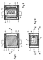
- a high-current fuse according to the invention a first embodiment (Fig. 1-3) has an approximate cuboid housing 1 made of electrically insulating Material, preferably ceramic, on the in Longitudinal opposite ends a first has electrical connection with a first End plate 2, a contact knife on the outside 3 carries and a second electrical connection with a second end plate 4, which on the outside Contact knife 5 carries. Which close the housing 1 End plates 2, 4 exist z.
- the interior of the housing is made of a partition plate 6 electrically conductive material, e.g. B. Aluminum in two Longitudinal successive sections divided.
- the slightly longer first section between the End plate 2 of the first electrical connection and the partition plate 6, contains a fuse element, the the end plate 2 with the partition plate 6 electrically connects in a leading way. It consists of three in a row consecutively arranged in parallel Silver coat bands 7 and is so in a known manner designed that in the event of overcurrent according to a standardized Characteristic curve according to a current dependent Response time melts and the current is interrupted.
- the housing In between the partition plate 6 and the end plate 4 of the second electrical connection lying section of the A choke is arranged inside the housing. It consists of a cylindrical winding 8 which the partition plate 6 with the end plate 4 electrically connects and one continuous core made of a ferromagnetic, preferably electrically insulating material, in particular ferrite, the than lying in the axis of the winding 8, surrounded by it massive round rod 9 is formed.
- the inductance of the Choke is chosen so that its impedance at frequencies on the order of magnitude of the network frequency, i.e. approx. 50 Hz is negligibly small, at high frequencies of 1 MHz up to 40 MHz, however, very large.
- the heavy current fuse can with respect to their Dimensions of sizes 1-3 of standard DIN 432620 correspond and z. B. be designed for 400 V and 400 A. You can always replace conventional fuses that comply with this standard.
- a second embodiment (Fig. 4, 5) of the Distinguishes high-current fuse according to the invention differs from the first only in that the winding 8 is a bit smaller and the core next to an in the axis of the same arranged rod 9 also a Has winding 8 surrounding shell, which consists of two half-shells 10a, b connected to the head ends of the rod 9 consists of a central air gap 11th are separated.
- the shell has two diametrically opposed to each other opposite, extending over their entire length sector-shaped openings 12a, b, through which the winding 8 with the partition plate 6 and the end plate 4 is electrically connected.
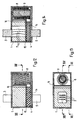
- a third embodiment (Fig. 6-8) also corresponds largely the first, but again extends as massive round rod 9 formed core essentially over the entire length of the housing 1 and extends from the End plate 2 of the first electrical connection to to the end plate 4 of the second electrical connection.
- the three silver sheathed strips 7 of the fuse element are around the Bar 9 arranged around.
- the embodiment stands out through particularly good mechanical stability.
- a fourth embodiment shows a different structure (Fig. 9-11) of the inventive high-current fuse.
- the core here is again as rod 9 formed, which is surrounded by the winding 8. Both However, they are rectangular in cross-section, that is, cuboid and the rod 9 is hollow, it has an in Continuous central passage on, in which is arranged the fuse element, which here consists of a single silver jacket 7.
- the winding 8 is from the end plate 2 of the first electrical connection through an insulation layer 13 and the silver jacket band 7 from the end plate 4 of the second electrical Connection separated by an insulation layer 14.
- the silver jacket band 7 closes through an opening in the first insulation layer 13 to the first end plate 2 on. Its opposite end is over one on the intermediate plate 15 resting on second insulation layer 14 with a z. B. trained as a return wire Return line 16 connected in a groove on the Outside of the rod 9 against the silver sheath band 7 the end of the next the first end plate 2 Winding 8 runs back. The opposite end of the Winding 8 is through an opening in the second Finally, insulation layer 14 with the end plate 4 connected. The current path therefore runs from the end plate 2 through the silver jacket band 7, the intermediate plate 15, back through the return line 16 and after one renewed reversal of direction through the winding 8 for End plate 4.
- This embodiment is particularly space-saving, in particular, it can be very short. You can therefore in the Dimensions of size 00-3 of standard DIN 43620 are manufactured and always replaced by conventional ones Heavy current fuses occur that meet this standard correspond.
- a fifth embodiment of the invention Heavy current fuse corresponds in its basic structure of the fourth embodiment, but is the winding 8 is arranged next to the fuse element, the between the contact knife 3 of the first electrical Connection and an intermediate plate 15 is arranged and again consists of three parallel silver jacket bands 7.
- the intermediate plate 15 is by means of a return line 16 with the first electrical connection adjacent end of the winding 8 connected, the opposite end to the end plate 4 of the second electrical connection. Between the latter and the intermediate plate 15 is an insulation layer 14.
- Die Winding 8 surrounds a core of one Insulation layer is surrounded. It can in turn be massive round rod 9 may be formed or from several parallel bars exist.
- the current path runs from the contact knife 3 of the first electrical connection via the silver jacket tapes 7 to Intermediate plate 15 and further on the return line 16, through the winding 8 and the end plate 4 to Contact knife 5 of the second electrical connection.
- the Heavy current fuse according to the invention (Fig. 15-17) with one arranged between the contact blades 3, 5 Winding 8 and an adjacent one, as Silver sheath band 7 trained fuse element similar constructed like the inventive high-current fuse according to the fifth embodiment.
- To the Contact knife 3 of the first electrical connection closes the end plate 2 of the same over the Fuse element is connected to an intermediate plate 15, which with distance - next to the end plate 4 of the second electrical connection is arranged.
- the intermediate plate 15 is via the return line 16 with the Connection plate 2 of the first electrical connection adjacent end of the winding 8 connected, the opposite end to the end plate 4 of the second electrical connection, which in turn Contact knife 5 carries the same.
- the winding 8 in turn surrounds a core that is considered to be solid Round rod 9 formed and surrounded by insulation is, which also forms an insulation layer 13, the the winding 8 and the return line 16 from the End plate 2 of the first electrical connection separates and an insulation layer 14 through which the Winding 8 with the end plate 4 of the second electrical connection is connected.
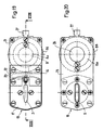
- a high-current fuse according to the invention corresponds to a seventh embodiment (Fig. 18-20) in the basic structure of those after the fifth Embodiment.
- the contact knife 3 of the first electrical connection is with a first End plate 17 mechanically and electrically connected, which is a fuse housing 18 made of electrically insulating Material closes on one side, which on the opposite side by a second end plate 19 is closed.
- the fuse housing 18 contains three parallel silver jacket bands 7, which the first end plate 17th and electrically connect the second end plate 19.
- the first end plate 17 carries one next to the contact knife 3 Folding detector 20.
- the second end plate 19 is with a Bolted intermediate plate 15, which with a next to the Fuse housing 18 returning return line 16 and one adjacent to the first end plate 17
- Connection plate 21 is a one-piece Z-shaped component forms.
- the first end plate 17 and the connection plate 21 are for mechanical reinforcement of the Heavy current fuse with one with both overlapping connecting plate 22 made of electrical screwed insulating material.
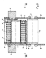
- connection plate 21 and a front plate 23 which are arranged at a distance in front of the second end plate 19 and with the same via spacers 24 made of electrical insulating material and which is connected to that of the second end plate 19 facing away from the outside Carries contact knife 5 of the second electrical connection, are coaxial an inner winding 8a and an outer Winding 8b arranged, which are electrically connected in parallel are.
- the reason for this arrangement is as follows:
- the Windings 8a, b consist of enameled winding wire of approximately rectangular cross-section, with the purpose of achieving a high number of turns for a given cross section longer side edge of the rectangle is aligned radially.
- the radial expansion of the winding wire is however limited by the fact that when winding the wire none disturbing twists, upsets or bends the same may occur, the winding distance would enlarge. So despite the given Cross-section limitation a high current carrying capacity is reached, the current is distributed over two windings.
- ferrite core Inside the inner winding 8b is one of one. Insulating sleeve 25 surrounded and arranged by ferrite core a cover 26 which has an opening in the front panel 23 closes, fixed.
- a massive rod-shaped Ferrite core can also be a ferrite tube or a parallel one Arrangement of thinner ferrite rods or tubes can be provided. Ferrite cores of different lengths can also be used be different by lids or inserts Thickness can be compensated.
- the heavy current fuse described is for high Suitable for amperages and yet compact and mechanical very stable and can be in an ordinary slot be used. It is usually not from one here shown housing made of electrically non-conductive material surrounded by the of the first end plate 17, the Connection plate 22 and the connecting plate 21 on the one hand and the front panel 23 on the other hand formed fronts leaves free. To facilitate insertion into one Slot and removing from such are the Connection plate 21 and the front plate 23 with one each Pull tab 27 provided.
- a high-current fuse according to the invention corresponds to an eighth embodiment (Fig. 21-23) in the basic structure of those after the sixth Embodiment, but the figures again show Construction details.
- the contact sword 3 of the first electrical connection is here with a front panel 23 screwed, which in turn with a first end plate 17th is screwed to which a fuse housing 18th connects and arranged in the same Silver jacket straps (not shown) which are electrically conductive connection between the first end plate 17 and produce a second end plate 19, which on opposite end of the fuse housing 18th closes.
- the first end plate 17 carries a folding detector 20th
- connection plate 21 is bent over Screwed connection tab 28 of the return line 16, which is returned along the fuse housing 18 and in one parallel to, and spaced from, the front panel 23 Connection plate 21 bends.
- the winding 8 rotates again a surrounded by an insulating sleeve 25 ferrite core 9. Zur mechanical reinforcement of the high-current fuse the closure plate 29 with one of the Return line 16 projecting connecting tab 30 screwed. Between the end plate 4 and the Connecting strap 30 must have a certain minimum distance are observed so that the u. U. considerable Voltages due to the inductance of the network at a Blowing of the high-current fuse will occur can not lead to arcing.
- spacers 24 are made of electrical arranged non-conductive material, which the Connect the end plate 2 with the closing plate 29, see above that the heavy current fuse is independent of the Winding 8 mechanically stable and to standards Dimensions is set. On the end plates 17, 19 are again pull tabs 27 screwed.
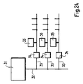
- FIG. 24 schematically shows a power distribution network, in which heavy current fuses according to the invention are used. From a transformer 31 - it can also to another branch point such.
- the individual branches 33 can approximately supply one building each.
Landscapes
- Engineering & Computer Science (AREA)
- Power Engineering (AREA)
- Fuses (AREA)
- Coupling Device And Connection With Printed Circuit (AREA)
- Superconductors And Manufacturing Methods Therefor (AREA)
- Emergency Protection Circuit Devices (AREA)
- Professional, Industrial, Or Sporting Protective Garments (AREA)
- Details Of Garments (AREA)
- Separation By Low-Temperature Treatments (AREA)
Description
- Fig. 1
- einen Längsschnitt durch eine erfindungsgemässe Starkstromschmelzsicherung gemäss einer ersten Ausführungsform, mit ungeschnittener Drossel,
- Fig. 2
- einen Längsschnitt entsprechend Fig. 1, längs II-II dort,
- Fig. 3
- einen Querschnitt längs III-III in Fig. 1,
- Fig. 4
- einen Längsschnitt durch eine erfindungsgemässe Starkstromschmelzsicherung gemäss einer zweiten Ausführungsform, mit teilweise ungeschnittener Drossel,
- Fig. 5
- einen Querschnitt längs V-V in Fig. 4,
- Fig. 6
- einen Längsschnitt durch eine erfindungsgemässe Starkstromschmelzsicherung gemäss einer dritten Ausführungsform, mit ungeschnittener Drossel,
- Fig. 7
- einen Längsschnitt entsprechend Fig. 6, längs VII-VII dort,
- Fig. 8
- einen Querschnitt längs VIII-VIII in Fig. 6,
- Fig. 9
- einen Längsschnitt durch eine erfindungsgemässe Starkstromschmelzsicherung gemäss einer vierten Ausführungsform, mit ungeschnittener Drossel,
- Fig. 10
- einen Querschnitt längs X-X in Fig. 9,
- Fig. 11
- einen Längsschnitt entsprechend Fig. 9, aber mit geschnittener Drossel,
- Fig. 12
- einen Längsschnitt durch eine erfindungsgemässe Starkstromschmelzsicherung gemäss einer fünften Ausführungsform, unmittelbar hinter der vorneliegenden Wand,
- Fig. 13
- einen Querschnitt längs XIII-XIII in Fig. 12,
- Fig. 14
- einen Längsschnitt längs XIV-XIV in Fig. 13,
- Fig. 15
- einen Längsschnitt durch eine erfindungsgemässe Starkstromschmelzsicherung gemäss einer sechsten Ausführungsform, unmittelbar hinter der vorneliegenden Wand,
- Fig. 16
- einen Querschnitt längs XVI-XVI in Fig. 15,
- Fig. 17
- einen Längsschnitt längs XVII-XVII in Fig. 16,
- Fig. 18
- einen Längsschnitt durch eine erfindungsgemässe Starkstromschmelzsicherung gemäss einer siebten Ausführungsform, die in ihrem grundsätzlichen Aufbau derjenigen nach der fünften Ausführungsform entspricht,
- Fig. 19
- eine Seitenansicht entsprechend Pfeil XIX in Fig. 18,
- Fig. 20
- eine Seitenansicht entsprechend Pfeil XX in Fig. 18,
- Fig. 21
- einen Längsschnitt durch eine erfindungsgemässe Starkstromschmelzsicherung gemäss einer achten Ausführungsform, die in ihrem grundsätzlichen Aufbau derjenigen nach der sechsten Ausführungsform entspricht,
- Fig. 22
- eine Seitenansicht entsprechend Pfeil XXII in Fig. 21,
- Fig. 23
- eine Seitenansicht entsprechend Pfeil XXIII in Fig. 18.und
- Fig. 24
- schematisch ein Stromverteilungsnetz, in welcher erfindungsgemässe Starkstromschmelzsicherungen eingesetzt sind.
Claims (13)
- Starkstromschmelzsicherung mit einem Gehäuse (1) aus elektrisch isolierendem Material und, an einander in Längsrichtung entgegengesetzten Enden desselben einem ersten elektrischen Anschluss und einem zweiten elektrischen Anschluss, welche über einen im Gehäuse (1) angeordneten Schmelzleiter elektrisch leitend verbunden sind, dadurch gekennzeichnet, dass die elektrisch leitende Verbindung zwischen dem ersten elektrischen Anschluss und dem zweiten elektrischen Anschluss über eine im Gehäuse (1) angeordnete, mit dem Schmelzleiter in Reihe liegende Drossel hergestellt ist.
- Starkstromschmelzsicherung nach Anspruch 1, dadurch gekennzeichnet, dass die Drossel mindestens eine Wicklung (8) umfasst und einen Kern aus ferromagnetischem, insbesondere elektrisch isolierendem Material aufweist, welcher mit der Wicklung (8) magnetisch gekoppelt ist.
- Starkstromschmelzsicherung nach Anspruch 2, dadurch gekennzeichnet, dass der Kern einen Stab (9) umfasst, der von der Wicklung (8) umgeben ist.
- Starkstromschmelzsicherung nach Anspruch 2 oder 3, dadurch gekennzeichnet, dass der Kern eine Schale umfasst, welche die Wicklung (8) aussen mindestens teilweise umgibt.
- Starkstromschmelzsicherung nach Anspruch 4, dadurch gekennzeichnet, dass die Schale zwei einander gegenüberliegende sektorförmige Oeffnungen (12a, 12b) aufweist.
- Starkstromsicherung nach Anspruch 4 oder 5, dadurch gekennzeichnet, dass die Schale durch einen umlaufenden Luftspalt (11) in zwei Halbschalen (10a, 10b) geteilt ist.
- Starkstromschmelzsicherung nach einem der Ansprüche 1 bis 6, dadurch gekennzeichnet, dass der Schmelzleiter und die Drossel in Längsrichtung aufeinanderfolgend im Gehäuse (1) angeordnet sind.
- Starkstromschmelzsicherung nach Anspruch 7, dadurch gekennzeichnet, dass der den Schmelzleiter enthaltende Teil des Gehäuseinneren und der die Drossel enthaltende Teil desselben durch eine querverlaufende Trennplatte (6) voneinander getrennt sind.
- Starkstromschmelzsicherung nach einem der Ansprüche 1 bis 6, dadurch gekennzeichnet, dass die Drossel den Schmelzleiter umgibt.
- Starkstromschmelzsicherung nach den Ansprüchen 3 und 9, dadurch gekennzeichnet, dass der Stab (9) hohl ausgebildet ist mit einer den Schmelzleiter aufnehmenden Durchführung und die Wicklung (8) mit dem Schmelzleiter durch eine ausserhalb des Stabes (9) angeordnete, dem Schmelzleiter entgegenlaufende Rückführung verbunden ist.
- Starkstromschmelzsicherung nach einem der Ansprüche 1 bis 6, dadurch gekennzeichnet, dass der Schmelzleiter und die Drossel parallel nebeneinander in Längsrichtung im Gehäuse (1) angeordnet sind.
- Starkstromschmelzsicherung nach einem der Ansprüche 1 bis 11, dadurch gekennzeichnet, dass die Drossel mindestens zwei koaxial angeordnete parallelgeschaltete Wicklungen (8a, 8b) umfasst.
- Stromverteilungsnetz mit mehreren galvanisch verbundenen Zweigen (33), dadurch gekennzeichnet, dass in jedem Zweig (33) am Eingang eine Starkstromschmelzsicherung (34) nach einem der Ansprüche 1 bis 11 liegt.
Priority Applications (1)
| Application Number | Priority Date | Filing Date | Title |
|---|---|---|---|
| EP99942700A EP1116252B1 (de) | 1998-09-24 | 1999-09-23 | Starkstromschmelzsicherung sowie stromverteilungsnetz |
Applications Claiming Priority (4)
| Application Number | Priority Date | Filing Date | Title |
|---|---|---|---|
| EP98810964A EP0996137A1 (de) | 1998-09-24 | 1998-09-24 | Starkstromschmelzsicherung |
| EP98810964 | 1998-09-24 | ||
| PCT/CH1999/000454 WO2000019475A1 (de) | 1998-09-24 | 1999-09-23 | Starkstromschmelzsicherung sowie stromverteilungsnetz |
| EP99942700A EP1116252B1 (de) | 1998-09-24 | 1999-09-23 | Starkstromschmelzsicherung sowie stromverteilungsnetz |
Publications (2)
| Publication Number | Publication Date |
|---|---|
| EP1116252A1 EP1116252A1 (de) | 2001-07-18 |
| EP1116252B1 true EP1116252B1 (de) | 2002-07-24 |
Family
ID=8236348
Family Applications (2)
| Application Number | Title | Priority Date | Filing Date |
|---|---|---|---|
| EP98810964A Withdrawn EP0996137A1 (de) | 1998-09-24 | 1998-09-24 | Starkstromschmelzsicherung |
| EP99942700A Expired - Lifetime EP1116252B1 (de) | 1998-09-24 | 1999-09-23 | Starkstromschmelzsicherung sowie stromverteilungsnetz |
Family Applications Before (1)
| Application Number | Title | Priority Date | Filing Date |
|---|---|---|---|
| EP98810964A Withdrawn EP0996137A1 (de) | 1998-09-24 | 1998-09-24 | Starkstromschmelzsicherung |
Country Status (14)
| Country | Link |
|---|---|
| EP (2) | EP0996137A1 (de) |
| JP (1) | JP2002526888A (de) |
| KR (1) | KR20010079736A (de) |
| CN (1) | CN1319242A (de) |
| AT (1) | ATE221251T1 (de) |
| AU (1) | AU5615399A (de) |
| BR (1) | BR9913105A (de) |
| CA (1) | CA2340772A1 (de) |
| DE (1) | DE59902140D1 (de) |
| ES (1) | ES2178898T3 (de) |
| ID (1) | ID27919A (de) |
| IL (1) | IL142062A0 (de) |
| NO (1) | NO20011508D0 (de) |
| WO (1) | WO2000019475A1 (de) |
Cited By (4)
| Publication number | Priority date | Publication date | Assignee | Title |
|---|---|---|---|---|
| DE102018213522A1 (de) * | 2018-08-10 | 2020-02-13 | Siemens Aktiengesellschaft | Schmelzsicherung, Sicherungskörper, System und Verfahren |
| US11508541B2 (en) | 2018-12-20 | 2022-11-22 | Siemens Aktiengesellschaft | Fuse having an integrated measuring function, and fuse body |
| US11923163B2 (en) | 2019-01-16 | 2024-03-05 | Siemens Aktiengesellschaft | Fuse element and fuse |
| US12191101B2 (en) | 2018-12-20 | 2025-01-07 | Siemens Aktiengesellschaft | Fuse having an integrated measuring function, and fuse body |
Families Citing this family (2)
| Publication number | Priority date | Publication date | Assignee | Title |
|---|---|---|---|---|
| DE102017126419A1 (de) * | 2017-02-08 | 2018-08-09 | Dehn + Söhne Gmbh + Co. Kg | Schmelzsicherung für Niederspannungsanwendungen |
| CN114899060B (zh) * | 2022-05-16 | 2023-06-06 | 保定市博远电气制造有限公司 | 一种用于电路控制的熔断器 |
Family Cites Families (6)
| Publication number | Priority date | Publication date | Assignee | Title |
|---|---|---|---|---|
| DE1836426U (de) * | 1960-11-23 | 1961-08-17 | Blaupunkt Werke Gmbh | Sicherungshalter fuer kleinsicherungen. |
| GB2060964A (en) * | 1979-10-20 | 1981-05-07 | Swish Prod | Electronic time-based control system |
| FR2471039A1 (fr) * | 1979-12-04 | 1981-06-12 | Ferodo Sa | Dispositif de fusible pour circuit electrique, notamment d'alimentation d'un moteur |
| DE9201490U1 (de) * | 1992-02-06 | 1993-03-11 | Siemens AG, 8000 München | Sicherungsgehäuse |
| EP0639840B1 (de) * | 1993-07-22 | 1996-12-04 | ABBPATENT GmbH | Spannverband für einen Stromrichter |
| JPH09330824A (ja) * | 1996-06-11 | 1997-12-22 | Nippon Electric Ind Co Ltd | ヒューズ機能を備えたインダクタ |
-
1998
- 1998-09-24 EP EP98810964A patent/EP0996137A1/de not_active Withdrawn
-
1999
- 1999-03-24 KR KR1020017002800A patent/KR20010079736A/ko not_active Withdrawn
- 1999-09-23 JP JP2000572885A patent/JP2002526888A/ja active Pending
- 1999-09-23 EP EP99942700A patent/EP1116252B1/de not_active Expired - Lifetime
- 1999-09-23 WO PCT/CH1999/000454 patent/WO2000019475A1/de not_active Ceased
- 1999-09-23 AU AU56153/99A patent/AU5615399A/en not_active Abandoned
- 1999-09-23 CA CA002340772A patent/CA2340772A1/en not_active Abandoned
- 1999-09-23 BR BR9913105-6A patent/BR9913105A/pt not_active IP Right Cessation
- 1999-09-23 DE DE59902140T patent/DE59902140D1/de not_active Expired - Fee Related
- 1999-09-23 ID IDW20010686A patent/ID27919A/id unknown
- 1999-09-23 ES ES99942700T patent/ES2178898T3/es not_active Expired - Lifetime
- 1999-09-23 AT AT99942700T patent/ATE221251T1/de not_active IP Right Cessation
- 1999-09-23 IL IL14206299A patent/IL142062A0/xx unknown
- 1999-09-23 CN CN99811304A patent/CN1319242A/zh active Pending
-
2001
- 2001-03-23 NO NO20011508A patent/NO20011508D0/no not_active Application Discontinuation
Cited By (7)
| Publication number | Priority date | Publication date | Assignee | Title |
|---|---|---|---|---|
| DE102018213522A1 (de) * | 2018-08-10 | 2020-02-13 | Siemens Aktiengesellschaft | Schmelzsicherung, Sicherungskörper, System und Verfahren |
| US11133144B2 (en) | 2018-08-10 | 2021-09-28 | Siemens Aktiengesellschaft | Fuse, fuse body, system and method |
| DE102018213522B4 (de) | 2018-08-10 | 2022-06-02 | Siemens Aktiengesellschaft | Schmelzsicherung, Sicherungskörper, System und Verfahren |
| DE102018213522C5 (de) | 2018-08-10 | 2026-03-12 | Siemens Aktiengesellschaft | Schmelzsicherung, Sicherungskörper, System und Verfahren |
| US11508541B2 (en) | 2018-12-20 | 2022-11-22 | Siemens Aktiengesellschaft | Fuse having an integrated measuring function, and fuse body |
| US12191101B2 (en) | 2018-12-20 | 2025-01-07 | Siemens Aktiengesellschaft | Fuse having an integrated measuring function, and fuse body |
| US11923163B2 (en) | 2019-01-16 | 2024-03-05 | Siemens Aktiengesellschaft | Fuse element and fuse |
Also Published As
| Publication number | Publication date |
|---|---|
| NO20011508L (no) | 2001-03-23 |
| AU5615399A (en) | 2000-04-17 |
| CN1319242A (zh) | 2001-10-24 |
| ES2178898T3 (es) | 2003-01-01 |
| EP1116252A1 (de) | 2001-07-18 |
| BR9913105A (pt) | 2001-05-08 |
| NO20011508D0 (no) | 2001-03-23 |
| CA2340772A1 (en) | 2000-04-06 |
| ATE221251T1 (de) | 2002-08-15 |
| KR20010079736A (ko) | 2001-08-22 |
| EP0996137A1 (de) | 2000-04-26 |
| IL142062A0 (en) | 2002-03-10 |
| JP2002526888A (ja) | 2002-08-20 |
| WO2000019475A1 (de) | 2000-04-06 |
| DE59902140D1 (de) | 2002-08-29 |
| ID27919A (id) | 2001-05-03 |
Similar Documents
| Publication | Publication Date | Title |
|---|---|---|
| EP0267403A2 (de) | Kapazitives Trennglied | |
| DE2139225A1 (de) | Gekapselte Hochspannungsanlage mit Druckgas und einem kapazitiven Spannungs teiler | |
| WO2000019475A1 (de) | Starkstromschmelzsicherung sowie stromverteilungsnetz | |
| EP0205397B1 (de) | Trennschalter für eine metallgekapselte, druckgasisolierte Hochspannungsschaltanlage | |
| DE1297217B (de) | Roehrenwicklung fuer Transformatoren | |
| DE2724920A1 (de) | Hochspannungsfeste signaluebertragungseinrichtung mit einem trennuebertrager | |
| EP0875971B1 (de) | Hochspannungsschaltanlage | |
| EP0141296B1 (de) | Schaltungsanordnung für Leistungsgrosstransformatoren | |
| DE69114370T2 (de) | Gasisolierte Schaltvorrichtung. | |
| DE9315875U1 (de) | Vorrichtung zur Einkopplung bzw. zum Empfang von elektrischen Signalen in ein bzw. aus einem Energieübertragungskabel | |
| EP2846336B1 (de) | Verbindung von mindestens vier elektrischen Leitern | |
| DE2018981C3 (de) | Mehrphasiger Generator | |
| DE69809688T2 (de) | Gasisolierte Hochspannungsleiter mit integriertem Leitungskondensator | |
| EP0283949B1 (de) | Mehrstellungs-Kommutierungstrenner für Hoch- und Mittelspannungs-Schaltanlagen | |
| DE69310424T2 (de) | Verbindungsblock für Mittelspannungsrelais mit Stromsensoren | |
| EP1183696B1 (de) | Kapazitiv gesteuerte hochspannungswicklung | |
| DE2747632C2 (de) | Antennenspeisesystem für Doppelpolarisation | |
| DE3414366A1 (de) | Metallgekapselte, gasisolierte schaltanlage | |
| DE102010004971A1 (de) | Vorrichtung für eine Schaltanlage | |
| DE2514634C2 (de) | Endverschluß für Hochspannungskabel mit wasserinnengekühltem Leiter zur Einführung in ölgefüllte Transformatoren | |
| DE3822081C2 (de) | ||
| DE1412955C (de) | Nachrichtenübertragungsanlage mit erdunsymmetrischem hocnfrequentem Drahtfunk | |
| DE955966C (de) | Einrichtung zum hochfrequenzmaessigen Kurzschliessen eines Leiterpaares | |
| DE102022208938A1 (de) | Elektrisches Gerät zum Anschluss an ein Hochspannungsnetz | |
| DE912458C (de) | Transformator, vorzugsweise fuer sehr hohe Frequenzen |
Legal Events
| Date | Code | Title | Description |
|---|---|---|---|
| PUAI | Public reference made under article 153(3) epc to a published international application that has entered the european phase |
Free format text: ORIGINAL CODE: 0009012 |
|
| 17P | Request for examination filed |
Effective date: 20010110 |
|
| AK | Designated contracting states |
Kind code of ref document: A1 Designated state(s): AT BE CH CY DE DK ES FI FR GB GR IE IT LI LU MC NL PT SE |
|
| RAP1 | Party data changed (applicant data changed or rights of an application transferred) |
Owner name: ASCOM POWERLINE COMMUNICATIONS AG |
|
| GRAG | Despatch of communication of intention to grant |
Free format text: ORIGINAL CODE: EPIDOS AGRA |
|
| 17Q | First examination report despatched |
Effective date: 20011004 |
|
| GRAG | Despatch of communication of intention to grant |
Free format text: ORIGINAL CODE: EPIDOS AGRA |
|
| GRAH | Despatch of communication of intention to grant a patent |
Free format text: ORIGINAL CODE: EPIDOS IGRA |
|
| GRAH | Despatch of communication of intention to grant a patent |
Free format text: ORIGINAL CODE: EPIDOS IGRA |
|
| GRAA | (expected) grant |
Free format text: ORIGINAL CODE: 0009210 |
|
| AK | Designated contracting states |
Kind code of ref document: B1 Designated state(s): AT BE CH CY DE DK ES FI FR GB GR IE IT LI LU MC NL PT SE |
|
| PG25 | Lapsed in a contracting state [announced via postgrant information from national office to epo] |
Ref country code: NL Free format text: LAPSE BECAUSE OF FAILURE TO SUBMIT A TRANSLATION OF THE DESCRIPTION OR TO PAY THE FEE WITHIN THE PRESCRIBED TIME-LIMIT Effective date: 20020724 Ref country code: IE Free format text: LAPSE BECAUSE OF FAILURE TO SUBMIT A TRANSLATION OF THE DESCRIPTION OR TO PAY THE FEE WITHIN THE PRESCRIBED TIME-LIMIT Effective date: 20020724 Ref country code: GR Free format text: LAPSE BECAUSE OF FAILURE TO SUBMIT A TRANSLATION OF THE DESCRIPTION OR TO PAY THE FEE WITHIN THE PRESCRIBED TIME-LIMIT Effective date: 20020724 |
|
| REF | Corresponds to: |
Ref document number: 221251 Country of ref document: AT Date of ref document: 20020815 Kind code of ref document: T |
|
| REG | Reference to a national code |
Ref country code: GB Ref legal event code: FG4D Free format text: NOT ENGLISH |
|
| REG | Reference to a national code |
Ref country code: CH Ref legal event code: EP |
|
| PGFP | Annual fee paid to national office [announced via postgrant information from national office to epo] |
Ref country code: AT Payment date: 20020808 Year of fee payment: 4 |
|
| PGFP | Annual fee paid to national office [announced via postgrant information from national office to epo] |
Ref country code: FI Payment date: 20020815 Year of fee payment: 4 |
|
| REG | Reference to a national code |
Ref country code: CH Ref legal event code: NV Representative=s name: KELLER & PARTNER PATENTANWAELTE AG |
|
| PGFP | Annual fee paid to national office [announced via postgrant information from national office to epo] |
Ref country code: SE Payment date: 20020821 Year of fee payment: 4 |
|
| REG | Reference to a national code |
Ref country code: IE Ref legal event code: FG4D Free format text: GERMAN |
|
| REF | Corresponds to: |
Ref document number: 59902140 Country of ref document: DE Date of ref document: 20020829 |
|
| GBT | Gb: translation of ep patent filed (gb section 77(6)(a)/1977) |
Effective date: 20020813 |
|
| PG25 | Lapsed in a contracting state [announced via postgrant information from national office to epo] |
Ref country code: LU Free format text: LAPSE BECAUSE OF NON-PAYMENT OF DUE FEES Effective date: 20020923 |
|
| PG25 | Lapsed in a contracting state [announced via postgrant information from national office to epo] |
Ref country code: CY Free format text: LAPSE BECAUSE OF FAILURE TO SUBMIT A TRANSLATION OF THE DESCRIPTION OR TO PAY THE FEE WITHIN THE PRESCRIBED TIME-LIMIT Effective date: 20020930 Ref country code: BE Free format text: LAPSE BECAUSE OF NON-PAYMENT OF DUE FEES Effective date: 20020930 |
|
| PG25 | Lapsed in a contracting state [announced via postgrant information from national office to epo] |
Ref country code: DK Free format text: LAPSE BECAUSE OF FAILURE TO SUBMIT A TRANSLATION OF THE DESCRIPTION OR TO PAY THE FEE WITHIN THE PRESCRIBED TIME-LIMIT Effective date: 20021024 |
|
| PG25 | Lapsed in a contracting state [announced via postgrant information from national office to epo] |
Ref country code: PT Free format text: LAPSE BECAUSE OF FAILURE TO SUBMIT A TRANSLATION OF THE DESCRIPTION OR TO PAY THE FEE WITHIN THE PRESCRIBED TIME-LIMIT Effective date: 20021029 |
|
| REG | Reference to a national code |
Ref country code: ES Ref legal event code: FG2A Ref document number: 2178898 Country of ref document: ES Kind code of ref document: T3 |
|
| NLV1 | Nl: lapsed or annulled due to failure to fulfill the requirements of art. 29p and 29m of the patents act | ||
| ET | Fr: translation filed | ||
| REG | Reference to a national code |
Ref country code: IE Ref legal event code: FD4D Ref document number: 1116252E Country of ref document: IE |
|
| BERE | Be: lapsed |
Owner name: *ASCOM POWERLINE COMMUNICATIONS A.G. Effective date: 20020930 |
|
| PG25 | Lapsed in a contracting state [announced via postgrant information from national office to epo] |
Ref country code: MC Free format text: LAPSE BECAUSE OF NON-PAYMENT OF DUE FEES Effective date: 20030401 |
|
| PLBE | No opposition filed within time limit |
Free format text: ORIGINAL CODE: 0009261 |
|
| STAA | Information on the status of an ep patent application or granted ep patent |
Free format text: STATUS: NO OPPOSITION FILED WITHIN TIME LIMIT |
|
| 26N | No opposition filed |
Effective date: 20030425 |
|
| PG25 | Lapsed in a contracting state [announced via postgrant information from national office to epo] |
Ref country code: FI Free format text: LAPSE BECAUSE OF NON-PAYMENT OF DUE FEES Effective date: 20030923 Ref country code: AT Free format text: LAPSE BECAUSE OF NON-PAYMENT OF DUE FEES Effective date: 20030923 |
|
| PG25 | Lapsed in a contracting state [announced via postgrant information from national office to epo] |
Ref country code: SE Free format text: LAPSE BECAUSE OF NON-PAYMENT OF DUE FEES Effective date: 20030924 |
|
| EUG | Se: european patent has lapsed | ||
| PGFP | Annual fee paid to national office [announced via postgrant information from national office to epo] |
Ref country code: FR Payment date: 20040812 Year of fee payment: 6 |
|
| PGFP | Annual fee paid to national office [announced via postgrant information from national office to epo] |
Ref country code: GB Payment date: 20040817 Year of fee payment: 6 |
|
| PGFP | Annual fee paid to national office [announced via postgrant information from national office to epo] |
Ref country code: DE Payment date: 20040818 Year of fee payment: 6 Ref country code: CH Payment date: 20040818 Year of fee payment: 6 |
|
| PGFP | Annual fee paid to national office [announced via postgrant information from national office to epo] |
Ref country code: ES Payment date: 20040906 Year of fee payment: 6 |
|
| PG25 | Lapsed in a contracting state [announced via postgrant information from national office to epo] |
Ref country code: IT Free format text: LAPSE BECAUSE OF NON-PAYMENT OF DUE FEES Effective date: 20050923 Ref country code: GB Free format text: LAPSE BECAUSE OF NON-PAYMENT OF DUE FEES Effective date: 20050923 |
|
| PG25 | Lapsed in a contracting state [announced via postgrant information from national office to epo] |
Ref country code: ES Free format text: LAPSE BECAUSE OF NON-PAYMENT OF DUE FEES Effective date: 20050924 |
|
| PG25 | Lapsed in a contracting state [announced via postgrant information from national office to epo] |
Ref country code: LI Free format text: LAPSE BECAUSE OF NON-PAYMENT OF DUE FEES Effective date: 20050930 Ref country code: CH Free format text: LAPSE BECAUSE OF NON-PAYMENT OF DUE FEES Effective date: 20050930 |
|
| PG25 | Lapsed in a contracting state [announced via postgrant information from national office to epo] |
Ref country code: DE Free format text: LAPSE BECAUSE OF NON-PAYMENT OF DUE FEES Effective date: 20060401 |
|
| REG | Reference to a national code |
Ref country code: CH Ref legal event code: PL |
|
| GBPC | Gb: european patent ceased through non-payment of renewal fee |
Effective date: 20050923 |
|
| PG25 | Lapsed in a contracting state [announced via postgrant information from national office to epo] |
Ref country code: FR Free format text: LAPSE BECAUSE OF NON-PAYMENT OF DUE FEES Effective date: 20060531 |
|
| REG | Reference to a national code |
Ref country code: FR Ref legal event code: ST Effective date: 20060531 |
|
| REG | Reference to a national code |
Ref country code: ES Ref legal event code: FD2A Effective date: 20050924 |