EP1114957A1 - Vanne pilotée - Google Patents
Vanne pilotée Download PDFInfo
- Publication number
- EP1114957A1 EP1114957A1 EP01300065A EP01300065A EP1114957A1 EP 1114957 A1 EP1114957 A1 EP 1114957A1 EP 01300065 A EP01300065 A EP 01300065A EP 01300065 A EP01300065 A EP 01300065A EP 1114957 A1 EP1114957 A1 EP 1114957A1
- Authority
- EP
- European Patent Office
- Prior art keywords
- valve
- piston
- shaft
- pilot
- chamber
- Prior art date
- Legal status (The legal status is an assumption and is not a legal conclusion. Google has not performed a legal analysis and makes no representation as to the accuracy of the status listed.)
- Withdrawn
Links
- 239000012530 fluid Substances 0.000 claims description 37
- 125000006850 spacer group Chemical group 0.000 claims description 16
- 230000000149 penetrating effect Effects 0.000 description 6
- 238000012856 packing Methods 0.000 description 5
- 230000002093 peripheral effect Effects 0.000 description 5
- 238000007789 sealing Methods 0.000 description 5
- 238000007599 discharging Methods 0.000 description 4
- 239000000565 sealant Substances 0.000 description 3
- 230000008878 coupling Effects 0.000 description 2
- 238000010168 coupling process Methods 0.000 description 2
- 238000005859 coupling reaction Methods 0.000 description 2
- 239000000428 dust Substances 0.000 description 1
- 230000003028 elevating effect Effects 0.000 description 1
- 238000005192 partition Methods 0.000 description 1
- 230000003449 preventive effect Effects 0.000 description 1
- 238000000638 solvent extraction Methods 0.000 description 1
- XLYOFNOQVPJJNP-UHFFFAOYSA-N water Substances O XLYOFNOQVPJJNP-UHFFFAOYSA-N 0.000 description 1
Images


Classifications
-
- F—MECHANICAL ENGINEERING; LIGHTING; HEATING; WEAPONS; BLASTING
- F16—ENGINEERING ELEMENTS AND UNITS; GENERAL MEASURES FOR PRODUCING AND MAINTAINING EFFECTIVE FUNCTIONING OF MACHINES OR INSTALLATIONS; THERMAL INSULATION IN GENERAL
- F16K—VALVES; TAPS; COCKS; ACTUATING-FLOATS; DEVICES FOR VENTING OR AERATING
- F16K11/00—Multiple-way valves, e.g. mixing valves; Pipe fittings incorporating such valves
-
- F—MECHANICAL ENGINEERING; LIGHTING; HEATING; WEAPONS; BLASTING
- F16—ENGINEERING ELEMENTS AND UNITS; GENERAL MEASURES FOR PRODUCING AND MAINTAINING EFFECTIVE FUNCTIONING OF MACHINES OR INSTALLATIONS; THERMAL INSULATION IN GENERAL
- F16K—VALVES; TAPS; COCKS; ACTUATING-FLOATS; DEVICES FOR VENTING OR AERATING
- F16K41/00—Spindle sealings
- F16K41/02—Spindle sealings with stuffing-box ; Sealing rings
-
- F—MECHANICAL ENGINEERING; LIGHTING; HEATING; WEAPONS; BLASTING
- F16—ENGINEERING ELEMENTS AND UNITS; GENERAL MEASURES FOR PRODUCING AND MAINTAINING EFFECTIVE FUNCTIONING OF MACHINES OR INSTALLATIONS; THERMAL INSULATION IN GENERAL
- F16K—VALVES; TAPS; COCKS; ACTUATING-FLOATS; DEVICES FOR VENTING OR AERATING
- F16K31/00—Actuating devices; Operating means; Releasing devices
- F16K31/12—Actuating devices; Operating means; Releasing devices actuated by fluid
- F16K31/122—Actuating devices; Operating means; Releasing devices actuated by fluid the fluid acting on a piston
- F16K31/1221—Actuating devices; Operating means; Releasing devices actuated by fluid the fluid acting on a piston one side of the piston being spring-loaded
Definitions
- the present invention relates to a pilot type two-port valve for allowing and preventing passage of a fluid such as air, oil, water and steam.
- pilot type two-port valve for vertically moving a pressure receiving element such as a piston or a diaphragm and a valve member coupled to the pressure receiving element and opening and closing a valve seat by supplying and discharging a pressure fluid to and from a pressure action chamber on one side of the pressure receiving element by switching a pilot valve, and for allowing and preventing flow of pressure fluid from an input port to an output port by opening and closing the valve seat.
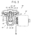
- the valve 100 comprises a main valve 101 having an input chamber 103 into which a pressure fluid is introduced from an input port, an output port 104, a valve seat 105 in a flow path connecting the input and output ports with each other and a valve member 106 opening/closing the valve seat 105, and a pilot valve 102.
- the main valve 101 opens and closes the valve seat 105 by vertically moving the valve member 106 via a valve rod 107.
- a pressure receiving element (a diaphragm in this example) 108 is fixedly attached to the valve rod 107 and biased in a valve closing direction by a return spring 109.
- the pressure receiving element 108 is vertically moved by supplying and discharging a pressure fluid to and from the pressure action chamber 110 by the pilot valve 102.
- a stepped portion having a male screw portion is provided on the end portion of the valve rod 107.
- a nut 124 is screwed onto the male screw portion 123, thereby fixing the pressure receiving element 108 to the valve rod 107.
- a member 126 having a hole 127 is fitted into an upper opening 125 in the body 111 of the main valve 101, a seal 128 is provided in the hole 127 and the valve rod 107 fixedly attached to the pressure receiving element 108 moves through and is guided by the hole 127.
- the pressure fluid is supplied to the pressure action chamber 110 through a supply channel 112 provided in the body 111 of the main valve 101.
- This pilot type two-port valve 100 has disadvantages as set out at (1) to (3) below because the valve rod 107 is fixedly attached to the pressure receiving element 108 and is guided by the hole 127 provided in the pivotal member 126 fitted into the upper opening 125 of the body 111 and the pressure fluid is supplied to the pressure chamber 110 through the supply channel 112 provided in the body 111 of the main valve 101.
- a pilot type two-port valve comprises a main valve having an input port, an output port, a valve seat in a channel connecting the input port to the output port, a valve member for opening and closing the valve seat, a shaft provided to be vertically movable in an axial direction and having a tip end to which the valve member is attached, a piston coupled to the shaft, and a pressure action chamber on one side of the piston, and a pilot valve for supplying a pilot fluid to the pressure action chamber.
- the shaft and the piston are coupled to each other at an intermediate position of the shaft by a male screw formed on an outer periphery on a central portion of the shaft and a female screw formed on an inner periphery of a central hole of the piston, a seal is provided between the shaft and the piston, and a stopper ring is attached to the outer periphery of the shaft so as to prevent the piston from loosening by stopping the stopper ring on an outer end portion of the piston; and the shaft has a tip end portion and a proximal end portion extending to both sides of the piston, respectively, and slidably supported by respective bearings.
- the main valve has a valve body having the input port, the output port and the valve seat, a cover attached to the valve body, and a spacer separating in airtight fashion an interior of the cover from an interior of the valve body;
- the cover has a chamber therein which is partitioned by the spacer, the piston is contained in the chamber, the tip end portion of the shaft penetrates the spacer and extends into the valve body, the proximal end portion of the shaft is fitted into a cylindrical guide portion formed at the valve body, and the bearings are provided at the guide portion and the spacer, respectively.
- the valve body has a pilot chamber for receiving a pilot fluid supplied from the pilot valve, and a through hole for communicating the pilot chamber with the pressure action chamber is provided inside of the proximal end portion of the shaft.
- the pressure action chamber is formed between one end face of the piston and the spacer
- a spring chamber is formed between the other end face of the piston and the cover
- a return spring for biasing the piston toward a valve closing direction is contained in the spring chamber.
- the shaft to which the valve member is attached is guided by the bearings at two portions, i.e., the tip end portion and the proximal end portion which are distanced from each other. Due to this, even if a biased force is exerted on the valve member by the pressure fluid flowing in the channel, it is possible to generate a force resisting the biased force on the shaft.
- the respective components contained in the cover can be easily assembled together by sequentially inserting and attaching the components from the opening side of the chamber in the cover. This facilitates the assembly and disassembly of these components contained in the cover, thereby making it possible to accurately assemble the two-port valve.
- the coupling of the shaft to the piston is made by providing the seal between the shaft and the piston, screwing the female screw provided at the piston into the male screw provided at the shaft and providing the stopper ring at the shaft to thereby prevent the piston from falling off. It is, therefore, possible to ensure locking the piston to the shaft and it is not necessary to provide special loosening preventive means as in the conventional case in which a nut is used. Furthermore, the shaft and the piston can be easily disassembled.
- the piston is driven by supplying the pilot fluid to the pressure action chamber using the pilot valve. Since the pilot fluid to the pressure action chamber is supplied by way of the through hole in the shaft, a channel for the supply of the pilot fluid is linear and simplified. Thus, the pilot pressure fluid flows smoothly and response characteristics are thereby enhanced.
- FIG. 1 is a longitudinal sectional view of an embodiment of a pilot type two-port valve according to the present invention. The valve is shown on the left of the centre line is in an opening state and on the right in a closed state.
- This pilot type two-port valve 1 is comprised of a main valve 2 and a pilot valve 3.
- the main valve 2 comprises of a valve body 4, a cover 5 airtightly attached to the upper surface of the valve body 4, a spacer 16 airtightly partitioning the interior of the valve body 4 from that of the cover 5, a piston 18 sliding inside of the cover 5, a shaft 15 coupled to the piston 18 and a valve member 25 attached to the tip end of the shaft 15.
- the valve body 4 comprises of an input port 6 into which a pressure fluid flows, an output port 7 out of which the pressure fluid flows, an annular valve seat 8 provided in a channel connecting the input and output ports, an attachment portion 9 to which the valve seat 8 is attached, and a valve chamber 10 formed at a position opposite to the valve seat 8 and leading to the output port 7.
- the valve member 25 is provided in the valve chamber 10.
- the cover 5 has a chamber, hereinafter referred to as a space portion 17, partitioned by the spacer 16, and is provided with a pilot port 11 and a breather port 12 near the upper end portion of the cover 5.
- the piston 18 is slidably provided in the space portion 17.
- the piston 18 partitions the interior of the space portion 17 into a spring chamber 17a above the piston 18 and a pressure action chamber 17b below the piston 18.
- the spring chamber 17a has a small diameter portion 19 having a diameter smaller than that of the space portion 17.
- a return spring 20 is contained in the small diameter portion 19 so as to be located between the piston 18 and the cover 5. This return spring 20 biases the piston 18 toward a valve closing direction.
- a step portion 60 is provided between the small diameter portion 19 and the space portion 17. This step portion 60 restricts the elevating position of the piston 18.
- a hollow cylindrical guide portion 22 extending from the cover 5 is provided at the upper position and at the centre of the small diameter portion 19.
- An extending portion 15b on the proximal end of the shaft 15 is slidably fitted into the guide portion 22 and airtight, slidably supported by a sealant 23 and a bearing 24 provided at the guide portion 22.
- the interior of the guide portion 22 becomes a pilot chamber 21 and a pilot fluid is supplied from the pilot valve 3 into the pilot chamber 21.
- the spacer 16 is in the form of a cylinder having a penetrating hole at the centre thereof.
- the spacer 16 has small diameter portions 16a and 16b near upper and lower end portions, respectively as well as a large diameter portion 16c between the small diameter portions 16a and 16b.
- the lower small diameter portion 16b is inserted into the valve chamber 10 of the valve body.
- the lower end face of the large diameter portion 16c is supported by a body wall around the valve chamber 10 and sealed by a sealant 31 attached to an annular groove on the body wall which groove is provided to surround the valve chamber 10.
- the upper end face of the large diameter portion 16c is positioned by a stopper ring 26 attached to an annular groove in the upper portion of an opening portion 14.
- annular groove is provided to attach a seal 27 thereto on the outer peripheral surface of the upper portion of the large diameter portion 16c.
- a bearing 50 for guiding the tip end portion 15c of the shaft 15 is attached to the neighbourhood of the upper end of the peripheral wall of a penetrating hole through which the tip end portion 15c penetrates.
- Annular grooves are provided between the lower end of the peripheral wall of the penetrating hole and the bearing 50 to attach seals 28, 29 and 30 to the respective grooves.
- the seal 27 is provided to shut off the pressure action chamber 17b from external air.
- the seal 28 is provided as a scraper to scrape away dust or the like adhering to the shaft.
- the seal 29 is provided to prevent a fluid from entering from the valve body side.
- the seal 30 is provided to seal the pressure of the pressure action chamber 17b.
- the proximal end portion 15b extending upward of the piston 18, of the shaft 15 has a smaller diameter than that of the tip end portion 15c extending downward of the piston 18.
- a through hole 15a to communicate the pilot chamber 21 with the pressure action chamber 17b is provided in the proximal end portion 15b.
- the valve member 25 is airtightly attached to a small diameter portion on the tip end of the tip end portion 15c penetrating into the spacer 16 and extending into the valve chamber 10 of the valve body 4, by a sealant 34.
- a piston packing 33 is provided around the piston 18 and the spring chamber 17a above the piston 18 communicates with the breather port 12.
- the pilot valve 3 provided above the cover 5 is switched to thereby communicate the pilot chamber 21 with the pilot port 11 or the breather port 12.
- pilot valve 3 If the pilot valve 3 is switched to thereby communicate the pilot chamber 21 with the pilot port 11, a pilot fluid is supplied to the pressure action chamber 17b by way of the through hole 15a.
- the piston 18 is, therefore, pushed up by fluid pressure against the spring force of the return spring 20.
- the valve member 25 is moved upward by the shaft 15, whereby the valve seat 8 opens and the pressure fluid of the input port 6 flows in the output port 7.
- pilot chamber 21 is communicated with the pilot port 11 or the breather port 12 by providing the pilot valve 3 above the cover 5. It will be appreciated that the pilot type two-port valve is not necessarily limited to this structure.
- pilot fluid pressure into the pilot port 11 through a three-port valve which is not shown in FIG. 1.
- the pilot port 11 suffices to communicate with the pilot chamber 21 and the pilot valve 3 shown therein can be dispensed with.
- the pressure fluid of the pilot chamber 21 is supplied and discharged by switching the three-port valve. It is, therefore, unnecessary to communicate the pilot chamber 21 with the breather port 12.
- FIG. 2 shows an embodiment of a structure by which the shaft 15 and the piston 18 are coupled with each other.
- the shaft 15 has an annular step portion 15d for stopping the piston 18 between the tip end portion 15c having a large diameter and the proximal end portion 15b having a small diameter.
- a male screw 15e is provided at a position at which the proximal end portion 15b is adjacent the step portion 15d.
- a sealing groove 61 is formed on the end portion of the male screw 15e on the step portion 15d side, and a groove 62 for containing a stopper ring is formed on the end portion of the male screw 15e opposite to the step portion 15d side.
- the piston 18 is in the form of a disk having a penetrating hole 18a at the centre thereof.
- An annular concave groove 18b for containing the piston packing 33 is provided on the outer peripheral surface of the piston 18.
- An annular concave portion 18c which becomes the seat of the return spring 20 is formed on the upper surface of the piston 18 at a position facing the space portion 19a.
- a female screw 18d is provided on the inner peripheral surface of the penetrating hole 18a.
- a seal 63 and a stopper ring 64 are attached to the grooves 61 and 62 of the shaft 15 to which the piston 18 is attached by the screws.
- the shaft 15 and the piston 18 are assembled together as follows.
- the seal 63 is attached to the sealing groove 61 of the shaft 15, the piston 18 is then inserted into the groove 61 from the extending portion 15b of the shaft 15, and the female screw 18d of the piston 18 is engaged with the male spring 15e of the shaft 15 while slidably contacting the piston 18 with the seal 63.
- the stopper ring 64 is attached to the groove 62 while the lower end surface of the piston 18 is pushed against the step portion 15d of the shaft 15.
- the piston 18 is locked to the shaft 15. Therefore, there is no need to specially provide means for preventing the piston 18 from loosening on the screw portions. Besides, the piston and the shaft can be disassembled.
- the shaft 15 to which the valve member 25 is attached is guided by the first bearing 50 provided in the spacer 16 within the cover 5 and the second bearing 24 provided at the guide portion 22.
- the operation of the shaft 15 is, therefore, guided by the upper and lower bearings 50 and 24 which are distanced from each other in shaft direction. Due to this, even if a biased force is exerted on the valve member 25 by the pressure fluid flowing in the channel, it is possible to generate a force resisting the biased force in the shaft 15.
- the respective components within the cover 5 can be easily assembled together only by sequentially inserting and attaching the components from the opening space side of the cover 5. This facilitates the assembly and disassembly of these components, thereby making it possible to accurately assemble a two-port valve.
- the groove 62 is formed on the end of the male screw 15e of the shaft 15 to which the piston 18 is attached by the screws and the stopper ring 64 is attached to the groove 62. Therefore, the piston 18 is locked to the shaft 15, no special means for preventing the piston 18 from loosening is necessary and the piston and the shaft can be disassembled.
- the pilot valve 3 is switched to supply and discharge the pressure fluid of the pressure action chamber 17b, thereby vertically moving the piston 18 to open and close the valve seat 8. Since the supply and discharge of the pressure fluid of the pressure action chamber 17b are conducted through the pilot chamber 21 communicated with the pilot valve 3 and the through hole 15a within the shaft 15, the extending portion 15b of the shaft 15 can be also used as a passage to supply and discharge a pressure fluid and a portion containing and guiding the extending portion 15b of the shaft 15 can be also used as a pilot chamber. This simplifies the structure for supplying and discharging the pressure fluid to and from the pressure action chamber 17. Besides, since the passage is linear, the connection of the passage can be made surely, economically connected and pilot pressure fluid flows smoothly, thereby improving response characteristics.
- the present invention provides a pilot type two-port valve which allows the shaft to which the valve member is connected to move smoothly, which produces less seal and piston packing wear, which has excellent sealing performance and excellent assembly and disassembly performance, and which can easily supply and discharge the pressure fluid to and from the pressure action chamber.
Landscapes
- Engineering & Computer Science (AREA)
- General Engineering & Computer Science (AREA)
- Mechanical Engineering (AREA)
- Fluid-Driven Valves (AREA)
- Safety Valves (AREA)
- Multiple-Way Valves (AREA)
Applications Claiming Priority (2)
| Application Number | Priority Date | Filing Date | Title |
|---|---|---|---|
| JP2000000877A JP2001193854A (ja) | 2000-01-06 | 2000-01-06 | パイロット形2ポート弁 |
| JP2000000877 | 2000-01-06 |
Publications (1)
| Publication Number | Publication Date |
|---|---|
| EP1114957A1 true EP1114957A1 (fr) | 2001-07-11 |
Family
ID=18530160
Family Applications (1)
| Application Number | Title | Priority Date | Filing Date |
|---|---|---|---|
| EP01300065A Withdrawn EP1114957A1 (fr) | 2000-01-06 | 2001-01-05 | Vanne pilotée |
Country Status (6)
| Country | Link |
|---|---|
| US (1) | US20010007353A1 (fr) |
| EP (1) | EP1114957A1 (fr) |
| JP (1) | JP2001193854A (fr) |
| KR (1) | KR20010070404A (fr) |
| CN (1) | CN1302966A (fr) |
| TW (1) | TW454842U (fr) |
Cited By (6)
| Publication number | Priority date | Publication date | Assignee | Title |
|---|---|---|---|---|
| WO2003016760A1 (fr) * | 2001-08-14 | 2003-02-27 | Sed Flow Control Gmbh | Vanne a membrane |
| EP1640649A1 (fr) * | 2004-09-28 | 2006-03-29 | Nordson Corporation | Soupape à membrane |
| ITMI20100130A1 (it) * | 2010-01-29 | 2011-07-30 | Caleffi Spa | Dispositivo valvolare a membrana per impianti termici, sistema per l'interruzione di un flusso avente il dispositivo valvolare a membrana, e impianto termico provvisto del sistema di interruzione stesso. |
| US8586258B2 (en) | 2010-09-03 | 2013-11-19 | GM Global Technology Operations LLC | Hydrogen/gas pressure controlled high pressure tank valves architecture |
| WO2015063285A1 (fr) * | 2013-11-04 | 2015-05-07 | Sames Technologies | Dispositif d'alimentation d'un projecteur en produit de revetement liquide |
| CN112770921A (zh) * | 2018-09-25 | 2021-05-07 | 亨德里克森美国有限责任公司 | 具有可调节最小输送压力的先导操作调节器 |
Families Citing this family (12)
| Publication number | Priority date | Publication date | Assignee | Title |
|---|---|---|---|---|
| JP2004092824A (ja) * | 2002-09-02 | 2004-03-25 | Fujikin Inc | 流体制御器 |
| KR101474786B1 (ko) * | 2006-05-05 | 2014-12-22 | 배트 홀딩 아게 | 진공밸브 구동장치 |
| JP3940429B1 (ja) * | 2006-10-02 | 2007-07-04 | 兼工業株式会社 | ウエハー形パイロット式バルブ |
| KR100864100B1 (ko) * | 2006-12-28 | 2008-10-16 | 주명택 | 파일롯밸브를 갖춘 유체 제어용 밸브유니트 |
| JP5806840B2 (ja) * | 2011-04-18 | 2015-11-10 | 株式会社ミヤワキ | 混合弁装置 |
| JP5837338B2 (ja) * | 2011-06-20 | 2015-12-24 | 株式会社ミヤワキ | 混合弁装置とそのガイド体取り出し方法 |
| CN102937192B (zh) * | 2012-10-26 | 2014-05-28 | 珠海艾迪西软件科技有限公司 | 一种二通阀 |
| DE102013001979A1 (de) * | 2013-02-05 | 2014-08-07 | Eisenmann Ag | Druckregler |
| JP6588207B2 (ja) * | 2014-12-26 | 2019-10-09 | 株式会社フジキン | バルブ |
| CN106382411A (zh) * | 2016-10-12 | 2017-02-08 | 诸暨市亿霸电子阀门有限公司 | 一种用于阀杆组件的密封结构以及该密封结构的密封方法 |
| JP7091634B2 (ja) * | 2017-11-15 | 2022-06-28 | いすゞ自動車株式会社 | 油圧制御弁 |
| CN112618921B (zh) * | 2020-12-23 | 2022-08-09 | 四川大学华西医院 | 一种基于柔性传感材料动态监测气囊压力的三腔二囊管 |
Citations (3)
| Publication number | Priority date | Publication date | Assignee | Title |
|---|---|---|---|---|
| US4187870A (en) * | 1977-05-06 | 1980-02-12 | Baker International Corporation | Valve actuator and pilot assembly therefor |
| US4795129A (en) * | 1985-01-29 | 1989-01-03 | Clark Richard J | Normally closed fluid switching logic element |
| US4934652A (en) * | 1989-12-11 | 1990-06-19 | Otis Engineering Corporation | Dual stage valve actuator |
-
2000
- 2000-01-06 JP JP2000000877A patent/JP2001193854A/ja active Pending
- 2000-12-14 TW TW089221725U patent/TW454842U/zh not_active IP Right Cessation
- 2000-12-18 US US09/737,582 patent/US20010007353A1/en not_active Abandoned
- 2000-12-29 CN CN00137086A patent/CN1302966A/zh active Pending
-
2001
- 2001-01-04 KR KR1020010000307A patent/KR20010070404A/ko not_active Application Discontinuation
- 2001-01-05 EP EP01300065A patent/EP1114957A1/fr not_active Withdrawn
Patent Citations (3)
| Publication number | Priority date | Publication date | Assignee | Title |
|---|---|---|---|---|
| US4187870A (en) * | 1977-05-06 | 1980-02-12 | Baker International Corporation | Valve actuator and pilot assembly therefor |
| US4795129A (en) * | 1985-01-29 | 1989-01-03 | Clark Richard J | Normally closed fluid switching logic element |
| US4934652A (en) * | 1989-12-11 | 1990-06-19 | Otis Engineering Corporation | Dual stage valve actuator |
Cited By (12)
| Publication number | Priority date | Publication date | Assignee | Title |
|---|---|---|---|---|
| WO2003016760A1 (fr) * | 2001-08-14 | 2003-02-27 | Sed Flow Control Gmbh | Vanne a membrane |
| EP1640649A1 (fr) * | 2004-09-28 | 2006-03-29 | Nordson Corporation | Soupape à membrane |
| ITMI20100130A1 (it) * | 2010-01-29 | 2011-07-30 | Caleffi Spa | Dispositivo valvolare a membrana per impianti termici, sistema per l'interruzione di un flusso avente il dispositivo valvolare a membrana, e impianto termico provvisto del sistema di interruzione stesso. |
| EP2354610A1 (fr) | 2010-01-29 | 2011-08-10 | Caleffi S.p.A. | Dispositif de soupape à diaphragme actionné par un fluide sous pression et ensemble formant commande de la soupape pour centrales thermiques |
| US8586258B2 (en) | 2010-09-03 | 2013-11-19 | GM Global Technology Operations LLC | Hydrogen/gas pressure controlled high pressure tank valves architecture |
| DE102011110903B4 (de) * | 2010-09-03 | 2015-10-08 | GM Global Technology Operations LLC (n. d. Gesetzen des Staates Delaware) | Brennstoffzellensystem |
| WO2015063285A1 (fr) * | 2013-11-04 | 2015-05-07 | Sames Technologies | Dispositif d'alimentation d'un projecteur en produit de revetement liquide |
| FR3012863A1 (fr) * | 2013-11-04 | 2015-05-08 | Sames Technologies | Dispositif d'alimentation d'un projecteur en produit de revetement liquide |
| US10035161B2 (en) | 2013-11-04 | 2018-07-31 | Sames Kremlin | Device for supplying a sprayer with a liquid coating product |
| RU2678152C2 (ru) * | 2013-11-04 | 2019-01-23 | Саме Кремлин | Устройство для подачи в разбрызгиватель жидкого покрывающего продукта |
| CN112770921A (zh) * | 2018-09-25 | 2021-05-07 | 亨德里克森美国有限责任公司 | 具有可调节最小输送压力的先导操作调节器 |
| CN112770921B (zh) * | 2018-09-25 | 2023-04-14 | 亨德里克森美国有限责任公司 | 具有可调节最小输送压力的先导操作调节器 |
Also Published As
| Publication number | Publication date |
|---|---|
| JP2001193854A (ja) | 2001-07-17 |
| US20010007353A1 (en) | 2001-07-12 |
| KR20010070404A (ko) | 2001-07-25 |
| TW454842U (en) | 2001-09-11 |
| CN1302966A (zh) | 2001-07-11 |
Similar Documents
| Publication | Publication Date | Title |
|---|---|---|
| EP1114957A1 (fr) | Vanne pilotée | |
| US4541607A (en) | High-pressure ball valve | |
| KR100275912B1 (ko) | 파일럿식 3포트 전환밸브 | |
| US6390442B2 (en) | Two-port valve | |
| JP2007016977A (ja) | パイロット式2ポート弁 | |
| RU2766162C2 (ru) | Клапан со встроенным уравновешивающим каналом | |
| JPS5949381B2 (ja) | 洗浄弁 | |
| US20070144595A1 (en) | Hollow piston valve | |
| KR100261985B1 (ko) | 베이스부착형전환밸브에부착하기위한압력조절밸브 | |
| US4905730A (en) | Override check valve | |
| KR20010070369A (ko) | 2포트 밸브 | |
| JP3719577B2 (ja) | 圧力室式弁 | |
| CN100478530C (zh) | 止回阀 | |
| JP4108596B2 (ja) | 手動操作機構部付き複合自動弁 | |
| CN210014049U (zh) | 一种分水阀芯 | |
| KR950002535B1 (ko) | 유압파일럿조작 방향제어밸브 | |
| US20100263363A1 (en) | Hydraulic control device and pressure switch | |
| US10816105B2 (en) | Valve drive system for a pneumatic or hydraulic valve | |
| JP4689318B2 (ja) | 開放弁 | |
| KR100522499B1 (ko) | 2포트 밸브 | |
| CN116197065B (zh) | 喷枪 | |
| CN113586108B (zh) | 电液控比例换向阀 | |
| CN111550575B (zh) | 一种双先导式滑阀 | |
| KR920008003B1 (ko) | 수도꼭지기구의 수격방지구조 | |
| CN117662552A (zh) | 先导液控单向阀及其阀芯组件 |
Legal Events
| Date | Code | Title | Description |
|---|---|---|---|
| PUAI | Public reference made under article 153(3) epc to a published international application that has entered the european phase |
Free format text: ORIGINAL CODE: 0009012 |
|
| 17P | Request for examination filed |
Effective date: 20010118 |
|
| AK | Designated contracting states |
Kind code of ref document: A1 Designated state(s): DE FR GB IT |
|
| AX | Request for extension of the european patent |
Free format text: AL;LT;LV;MK;RO;SI |
|
| AKX | Designation fees paid |
Free format text: DE FR GB IT |
|
| STAA | Information on the status of an ep patent application or granted ep patent |
Free format text: STATUS: THE APPLICATION IS DEEMED TO BE WITHDRAWN |
|
| 18D | Application deemed to be withdrawn |
Effective date: 20020112 |