EP1114777A1 - Packaging method and packaging apparatus - Google Patents
Packaging method and packaging apparatus Download PDFInfo
- Publication number
- EP1114777A1 EP1114777A1 EP00925623A EP00925623A EP1114777A1 EP 1114777 A1 EP1114777 A1 EP 1114777A1 EP 00925623 A EP00925623 A EP 00925623A EP 00925623 A EP00925623 A EP 00925623A EP 1114777 A1 EP1114777 A1 EP 1114777A1
- Authority
- EP
- European Patent Office
- Prior art keywords
- tray
- film
- hot
- swivel
- rollers
- Prior art date
- Legal status (The legal status is an assumption and is not a legal conclusion. Google has not performed a legal analysis and makes no representation as to the accuracy of the status listed.)
- Withdrawn
Links
- 238000004806 packaging method and process Methods 0.000 title claims abstract description 83
- 238000000034 method Methods 0.000 title claims description 50
- 230000007246 mechanism Effects 0.000 claims abstract description 198
- 229920001971 elastomer Polymers 0.000 claims description 14
- 239000000806 elastomer Substances 0.000 claims description 13
- 229920001973 fluoroelastomer Polymers 0.000 claims description 6
- 229910052710 silicon Inorganic materials 0.000 claims description 6
- 239000010703 silicon Substances 0.000 claims description 6
- 229920002379 silicone rubber Polymers 0.000 claims description 6
- 230000008859 change Effects 0.000 abstract description 7
- 229920006302 stretch film Polymers 0.000 description 64
- 230000032258 transport Effects 0.000 description 33
- 238000007789 sealing Methods 0.000 description 31
- 238000010438 heat treatment Methods 0.000 description 13
- 238000003466 welding Methods 0.000 description 10
- 235000013305 food Nutrition 0.000 description 8
- 239000000463 material Substances 0.000 description 6
- 230000007723 transport mechanism Effects 0.000 description 6
- 238000005520 cutting process Methods 0.000 description 5
- 230000008569 process Effects 0.000 description 4
- 229920005989 resin Polymers 0.000 description 4
- 239000011347 resin Substances 0.000 description 4
- 230000037303 wrinkles Effects 0.000 description 4
- 241000251468 Actinopterygii Species 0.000 description 3
- 230000002950 deficient Effects 0.000 description 3
- 235000013372 meat Nutrition 0.000 description 3
- 238000012858 packaging process Methods 0.000 description 3
- 239000012858 resilient material Substances 0.000 description 3
- 238000005096 rolling process Methods 0.000 description 3
- 229920003051 synthetic elastomer Polymers 0.000 description 3
- 239000005061 synthetic rubber Substances 0.000 description 3
- 239000000853 adhesive Substances 0.000 description 2
- 230000001070 adhesive effect Effects 0.000 description 2
- 230000006866 deterioration Effects 0.000 description 2
- 239000000155 melt Substances 0.000 description 2
- 235000021067 refined food Nutrition 0.000 description 2
- 230000004044 response Effects 0.000 description 2
- 230000000284 resting effect Effects 0.000 description 2
- 235000012046 side dish Nutrition 0.000 description 2
- 238000002604 ultrasonography Methods 0.000 description 2
- 235000001674 Agaricus brunnescens Nutrition 0.000 description 1
- 240000001462 Pleurotus ostreatus Species 0.000 description 1
- 235000012489 doughnuts Nutrition 0.000 description 1
- 239000013013 elastic material Substances 0.000 description 1
- 238000002360 preparation method Methods 0.000 description 1
- 238000003825 pressing Methods 0.000 description 1
- 239000005060 rubber Substances 0.000 description 1
Images









Classifications
-
- B—PERFORMING OPERATIONS; TRANSPORTING
- B65—CONVEYING; PACKING; STORING; HANDLING THIN OR FILAMENTARY MATERIAL
- B65B—MACHINES, APPARATUS OR DEVICES FOR, OR METHODS OF, PACKAGING ARTICLES OR MATERIALS; UNPACKING
- B65B51/00—Devices for, or methods of, sealing or securing package folds or closures; Devices for gathering or twisting wrappers, or necks of bags
- B65B51/10—Applying or generating heat or pressure or combinations thereof
-
- B—PERFORMING OPERATIONS; TRANSPORTING
- B29—WORKING OF PLASTICS; WORKING OF SUBSTANCES IN A PLASTIC STATE IN GENERAL
- B29C—SHAPING OR JOINING OF PLASTICS; SHAPING OF MATERIAL IN A PLASTIC STATE, NOT OTHERWISE PROVIDED FOR; AFTER-TREATMENT OF THE SHAPED PRODUCTS, e.g. REPAIRING
- B29C66/00—General aspects of processes or apparatus for joining preformed parts
- B29C66/80—General aspects of machine operations or constructions and parts thereof
- B29C66/84—Specific machine types or machines suitable for specific applications
- B29C66/841—Machines or tools adaptable for making articles of different dimensions or shapes or for making joints of different dimensions
- B29C66/8414—Machines or tools adaptable for making articles of different dimensions or shapes or for making joints of different dimensions of different diameter
-
- B—PERFORMING OPERATIONS; TRANSPORTING
- B29—WORKING OF PLASTICS; WORKING OF SUBSTANCES IN A PLASTIC STATE IN GENERAL
- B29C—SHAPING OR JOINING OF PLASTICS; SHAPING OF MATERIAL IN A PLASTIC STATE, NOT OTHERWISE PROVIDED FOR; AFTER-TREATMENT OF THE SHAPED PRODUCTS, e.g. REPAIRING
- B29C65/00—Joining or sealing of preformed parts, e.g. welding of plastics materials; Apparatus therefor
- B29C65/02—Joining or sealing of preformed parts, e.g. welding of plastics materials; Apparatus therefor by heating, with or without pressure
- B29C65/18—Joining or sealing of preformed parts, e.g. welding of plastics materials; Apparatus therefor by heating, with or without pressure using heated tools
-
- B—PERFORMING OPERATIONS; TRANSPORTING
- B29—WORKING OF PLASTICS; WORKING OF SUBSTANCES IN A PLASTIC STATE IN GENERAL
- B29C—SHAPING OR JOINING OF PLASTICS; SHAPING OF MATERIAL IN A PLASTIC STATE, NOT OTHERWISE PROVIDED FOR; AFTER-TREATMENT OF THE SHAPED PRODUCTS, e.g. REPAIRING
- B29C65/00—Joining or sealing of preformed parts, e.g. welding of plastics materials; Apparatus therefor
- B29C65/74—Joining or sealing of preformed parts, e.g. welding of plastics materials; Apparatus therefor by welding and severing, or by joining and severing, the severing being performed in the area to be joined, next to the area to be joined, in the joint area or next to the joint area
- B29C65/749—Removing scrap
-
- B—PERFORMING OPERATIONS; TRANSPORTING
- B29—WORKING OF PLASTICS; WORKING OF SUBSTANCES IN A PLASTIC STATE IN GENERAL
- B29C—SHAPING OR JOINING OF PLASTICS; SHAPING OF MATERIAL IN A PLASTIC STATE, NOT OTHERWISE PROVIDED FOR; AFTER-TREATMENT OF THE SHAPED PRODUCTS, e.g. REPAIRING
- B29C66/00—General aspects of processes or apparatus for joining preformed parts
- B29C66/01—General aspects dealing with the joint area or with the area to be joined
- B29C66/05—Particular design of joint configurations
- B29C66/10—Particular design of joint configurations particular design of the joint cross-sections
- B29C66/11—Joint cross-sections comprising a single joint-segment, i.e. one of the parts to be joined comprising a single joint-segment in the joint cross-section
- B29C66/112—Single lapped joints
-
- B—PERFORMING OPERATIONS; TRANSPORTING
- B29—WORKING OF PLASTICS; WORKING OF SUBSTANCES IN A PLASTIC STATE IN GENERAL
- B29C—SHAPING OR JOINING OF PLASTICS; SHAPING OF MATERIAL IN A PLASTIC STATE, NOT OTHERWISE PROVIDED FOR; AFTER-TREATMENT OF THE SHAPED PRODUCTS, e.g. REPAIRING
- B29C66/00—General aspects of processes or apparatus for joining preformed parts
- B29C66/01—General aspects dealing with the joint area or with the area to be joined
- B29C66/05—Particular design of joint configurations
- B29C66/10—Particular design of joint configurations particular design of the joint cross-sections
- B29C66/13—Single flanged joints; Fin-type joints; Single hem joints; Edge joints; Interpenetrating fingered joints; Other specific particular designs of joint cross-sections not provided for in groups B29C66/11 - B29C66/12
- B29C66/131—Single flanged joints, i.e. one of the parts to be joined being rigid and flanged in the joint area
-
- B—PERFORMING OPERATIONS; TRANSPORTING
- B29—WORKING OF PLASTICS; WORKING OF SUBSTANCES IN A PLASTIC STATE IN GENERAL
- B29C—SHAPING OR JOINING OF PLASTICS; SHAPING OF MATERIAL IN A PLASTIC STATE, NOT OTHERWISE PROVIDED FOR; AFTER-TREATMENT OF THE SHAPED PRODUCTS, e.g. REPAIRING
- B29C66/00—General aspects of processes or apparatus for joining preformed parts
- B29C66/01—General aspects dealing with the joint area or with the area to be joined
- B29C66/344—Stretching or tensioning the joint area during joining
-
- B—PERFORMING OPERATIONS; TRANSPORTING
- B29—WORKING OF PLASTICS; WORKING OF SUBSTANCES IN A PLASTIC STATE IN GENERAL
- B29C—SHAPING OR JOINING OF PLASTICS; SHAPING OF MATERIAL IN A PLASTIC STATE, NOT OTHERWISE PROVIDED FOR; AFTER-TREATMENT OF THE SHAPED PRODUCTS, e.g. REPAIRING
- B29C66/00—General aspects of processes or apparatus for joining preformed parts
- B29C66/50—General aspects of joining tubular articles; General aspects of joining long products, i.e. bars or profiled elements; General aspects of joining single elements to tubular articles, hollow articles or bars; General aspects of joining several hollow-preforms to form hollow or tubular articles
- B29C66/51—Joining tubular articles, profiled elements or bars; Joining single elements to tubular articles, hollow articles or bars; Joining several hollow-preforms to form hollow or tubular articles
- B29C66/53—Joining single elements to tubular articles, hollow articles or bars
- B29C66/534—Joining single elements to open ends of tubular or hollow articles or to the ends of bars
- B29C66/5346—Joining single elements to open ends of tubular or hollow articles or to the ends of bars said single elements being substantially flat
- B29C66/53461—Joining single elements to open ends of tubular or hollow articles or to the ends of bars said single elements being substantially flat joining substantially flat covers and/or substantially flat bottoms to open ends of container bodies
-
- B—PERFORMING OPERATIONS; TRANSPORTING
- B29—WORKING OF PLASTICS; WORKING OF SUBSTANCES IN A PLASTIC STATE IN GENERAL
- B29C—SHAPING OR JOINING OF PLASTICS; SHAPING OF MATERIAL IN A PLASTIC STATE, NOT OTHERWISE PROVIDED FOR; AFTER-TREATMENT OF THE SHAPED PRODUCTS, e.g. REPAIRING
- B29C66/00—General aspects of processes or apparatus for joining preformed parts
- B29C66/50—General aspects of joining tubular articles; General aspects of joining long products, i.e. bars or profiled elements; General aspects of joining single elements to tubular articles, hollow articles or bars; General aspects of joining several hollow-preforms to form hollow or tubular articles
- B29C66/65—General aspects of joining tubular articles; General aspects of joining long products, i.e. bars or profiled elements; General aspects of joining single elements to tubular articles, hollow articles or bars; General aspects of joining several hollow-preforms to form hollow or tubular articles with a relative motion between the article and the welding tool
- B29C66/652—General aspects of joining tubular articles; General aspects of joining long products, i.e. bars or profiled elements; General aspects of joining single elements to tubular articles, hollow articles or bars; General aspects of joining several hollow-preforms to form hollow or tubular articles with a relative motion between the article and the welding tool moving the welding tool around the fixed article
-
- B—PERFORMING OPERATIONS; TRANSPORTING
- B29—WORKING OF PLASTICS; WORKING OF SUBSTANCES IN A PLASTIC STATE IN GENERAL
- B29C—SHAPING OR JOINING OF PLASTICS; SHAPING OF MATERIAL IN A PLASTIC STATE, NOT OTHERWISE PROVIDED FOR; AFTER-TREATMENT OF THE SHAPED PRODUCTS, e.g. REPAIRING
- B29C66/00—General aspects of processes or apparatus for joining preformed parts
- B29C66/70—General aspects of processes or apparatus for joining preformed parts characterised by the composition, physical properties or the structure of the material of the parts to be joined; Joining with non-plastics material
- B29C66/73—General aspects of processes or apparatus for joining preformed parts characterised by the composition, physical properties or the structure of the material of the parts to be joined; Joining with non-plastics material characterised by the intensive physical properties of the material of the parts to be joined, by the optical properties of the material of the parts to be joined, by the extensive physical properties of the parts to be joined, by the state of the material of the parts to be joined or by the material of the parts to be joined being a thermoplastic or a thermoset
- B29C66/739—General aspects of processes or apparatus for joining preformed parts characterised by the composition, physical properties or the structure of the material of the parts to be joined; Joining with non-plastics material characterised by the intensive physical properties of the material of the parts to be joined, by the optical properties of the material of the parts to be joined, by the extensive physical properties of the parts to be joined, by the state of the material of the parts to be joined or by the material of the parts to be joined being a thermoplastic or a thermoset characterised by the material of the parts to be joined being a thermoplastic or a thermoset
- B29C66/7392—General aspects of processes or apparatus for joining preformed parts characterised by the composition, physical properties or the structure of the material of the parts to be joined; Joining with non-plastics material characterised by the intensive physical properties of the material of the parts to be joined, by the optical properties of the material of the parts to be joined, by the extensive physical properties of the parts to be joined, by the state of the material of the parts to be joined or by the material of the parts to be joined being a thermoplastic or a thermoset characterised by the material of the parts to be joined being a thermoplastic or a thermoset characterised by the material of at least one of the parts being a thermoplastic
- B29C66/73921—General aspects of processes or apparatus for joining preformed parts characterised by the composition, physical properties or the structure of the material of the parts to be joined; Joining with non-plastics material characterised by the intensive physical properties of the material of the parts to be joined, by the optical properties of the material of the parts to be joined, by the extensive physical properties of the parts to be joined, by the state of the material of the parts to be joined or by the material of the parts to be joined being a thermoplastic or a thermoset characterised by the material of the parts to be joined being a thermoplastic or a thermoset characterised by the material of at least one of the parts being a thermoplastic characterised by the materials of both parts being thermoplastics
-
- B—PERFORMING OPERATIONS; TRANSPORTING
- B29—WORKING OF PLASTICS; WORKING OF SUBSTANCES IN A PLASTIC STATE IN GENERAL
- B29C—SHAPING OR JOINING OF PLASTICS; SHAPING OF MATERIAL IN A PLASTIC STATE, NOT OTHERWISE PROVIDED FOR; AFTER-TREATMENT OF THE SHAPED PRODUCTS, e.g. REPAIRING
- B29C66/00—General aspects of processes or apparatus for joining preformed parts
- B29C66/80—General aspects of machine operations or constructions and parts thereof
- B29C66/81—General aspects of the pressing elements, i.e. the elements applying pressure on the parts to be joined in the area to be joined, e.g. the welding jaws or clamps
- B29C66/816—General aspects of the pressing elements, i.e. the elements applying pressure on the parts to be joined in the area to be joined, e.g. the welding jaws or clamps characterised by the mounting of the pressing elements, e.g. of the welding jaws or clamps
- B29C66/8163—Self-aligning to the joining plane, e.g. mounted on a ball and socket
-
- B—PERFORMING OPERATIONS; TRANSPORTING
- B29—WORKING OF PLASTICS; WORKING OF SUBSTANCES IN A PLASTIC STATE IN GENERAL
- B29C—SHAPING OR JOINING OF PLASTICS; SHAPING OF MATERIAL IN A PLASTIC STATE, NOT OTHERWISE PROVIDED FOR; AFTER-TREATMENT OF THE SHAPED PRODUCTS, e.g. REPAIRING
- B29C66/00—General aspects of processes or apparatus for joining preformed parts
- B29C66/80—General aspects of machine operations or constructions and parts thereof
- B29C66/83—General aspects of machine operations or constructions and parts thereof characterised by the movement of the joining or pressing tools
- B29C66/832—Reciprocating joining or pressing tools
- B29C66/8322—Joining or pressing tools reciprocating along one axis
-
- B—PERFORMING OPERATIONS; TRANSPORTING
- B29—WORKING OF PLASTICS; WORKING OF SUBSTANCES IN A PLASTIC STATE IN GENERAL
- B29C—SHAPING OR JOINING OF PLASTICS; SHAPING OF MATERIAL IN A PLASTIC STATE, NOT OTHERWISE PROVIDED FOR; AFTER-TREATMENT OF THE SHAPED PRODUCTS, e.g. REPAIRING
- B29C66/00—General aspects of processes or apparatus for joining preformed parts
- B29C66/80—General aspects of machine operations or constructions and parts thereof
- B29C66/84—Specific machine types or machines suitable for specific applications
- B29C66/849—Packaging machines
-
- B—PERFORMING OPERATIONS; TRANSPORTING
- B65—CONVEYING; PACKING; STORING; HANDLING THIN OR FILAMENTARY MATERIAL
- B65B—MACHINES, APPARATUS OR DEVICES FOR, OR METHODS OF, PACKAGING ARTICLES OR MATERIALS; UNPACKING
- B65B7/00—Closing containers or receptacles after filling
- B65B7/16—Closing semi-rigid or rigid containers or receptacles not deformed by, or not taking-up shape of, contents, e.g. boxes or cartons
- B65B7/162—Closing semi-rigid or rigid containers or receptacles not deformed by, or not taking-up shape of, contents, e.g. boxes or cartons by feeding web material to securing means
- B65B7/164—Securing by heat-sealing
-
- B—PERFORMING OPERATIONS; TRANSPORTING
- B29—WORKING OF PLASTICS; WORKING OF SUBSTANCES IN A PLASTIC STATE IN GENERAL
- B29C—SHAPING OR JOINING OF PLASTICS; SHAPING OF MATERIAL IN A PLASTIC STATE, NOT OTHERWISE PROVIDED FOR; AFTER-TREATMENT OF THE SHAPED PRODUCTS, e.g. REPAIRING
- B29C65/00—Joining or sealing of preformed parts, e.g. welding of plastics materials; Apparatus therefor
- B29C65/02—Joining or sealing of preformed parts, e.g. welding of plastics materials; Apparatus therefor by heating, with or without pressure
- B29C65/18—Joining or sealing of preformed parts, e.g. welding of plastics materials; Apparatus therefor by heating, with or without pressure using heated tools
- B29C65/24—Joining or sealing of preformed parts, e.g. welding of plastics materials; Apparatus therefor by heating, with or without pressure using heated tools characterised by the means for heating the tool
- B29C65/245—Joining or sealing of preformed parts, e.g. welding of plastics materials; Apparatus therefor by heating, with or without pressure using heated tools characterised by the means for heating the tool the heat transfer being achieved contactless, e.g. by radiation
Definitions
- the present invention relates to a packaging method and packaging apparatus. More particularly, the present invention relates to a packaging method and packaging apparatus wherein a tray, having a flange and an opening surrounded by said flange on its upper face and containing an article to be packaged, is covered with a film over the opening and the film is welded to the flange.
- the overlap method involves putting the food product into a tray and wrapping the entire tray with a film.
- planar size of the film must be several times larger than the planar size of the tray because both the tray and the entire food product must be covered and the ends of the film must overlap in order to form a seal. Furthermore, such packages are often sealed by pressing a hot plate against the overlapped ends of the film on the bottom of the tray, which results in an inferior seal.
- top-seal method another method (hereinafter called the “top-seal method”) is used instead of the overlap method.
- the top-seal method the film is placed only over the opening provided in the upper face of the tray and the film is thermally welded to the tray along the periphery of the hole.
- Using the top-seal method can reduce film consumption by half in comparison with the overlap method.
- the top-seal method has been used chiefly for packaging shimeji and other varieties of mushroom.
- One common form of the top-seal method is to apply an adhesive to the sides of the tray around the opening and bond the ends of the film to the tray when the film is placed over the opening.
- Another common form is to sandwich the tray and a piece of film that is larger than the planar size of the tray between two tools and apply pressure and heat to thermally weld the film to the tray.
- top-seal methods require tooling matched to the size and shape of the tray. Consequently, industries that need to use multiple tray types to package a variety of different articles often use the overlap method instead of the top-seal method. Although the top-seal method provides such merits as reduced film consumption and improved sealing characteristics, it is often impractical because a separate set of tools must be prepared for each different size and shape of tray.
- the object of the present invention is to provide a packaging method and corresponding packaging apparatus that allow an article placed on a tray to be sealed with a film using the top-seal method but do not require the preparation of tooling for each different size and shape of tray.
- a packaging method in accordance with claim 1 is provided with first, second, third, and fourth steps.
- the article to be packaged is put on a tray having an opening in its upper face;
- the opening in the tray is covered with a film;
- a heated hot member is touched, in a direction intersecting with a vertical direction, against the film on a portion of the tray near the opening where the film touches; and in the fourth step, at least one of the hot member or the tray is moved.
- a food product or other article is placed on a tray.
- the opening in the upper face of the tray is covered with a film so that the film is touching a portion of the periphery of the tray opening.
- the film on a portion of the tray near the opening where the film touches is pressed with a heated hot member in a direction intersecting with a vertical direction. In other words, the hot member is applied at an angle to a portion of the tray near the opening.
- at least one of the hot member or the tray is moved while the hot member being applied at an angle to a portion of the tray near the opening. As a result, the entire portion of the film that is touching the tray in the area surrounding the opening is thermally welded to the tray.
- the hot member since the hot member is applied to a portion of the tray near the opening from a direction that intersects with a vertical direction, the hot member only comes in contact with a portion of the tray near the opening and does not come in contact with the portion of the film covering the tray opening. Consequently, the portion of the film that covers the opening is less likely to melt or develop tiny holes.
- a pressure applying mechanism and controller be provided so that the pressure at which the hot member is applied to a portion of the tray near the opening and the speed at which the hot member and the periphery of the tray opening are moved relative to each other can be set to levels that are well matched to the materials from which the tray and film are made. It is also preferred that a controller and an angle adjustment mechanism be provided so that the degree to which the heating means heats the hot member and the angle at which the hot member is touched against the portion of the tray near the opening can be adjusted as necessary and appropriate.
- a packaging method in accordance with claim 2 is a method as recited in claim 1, wherein, either one or two or more hot members are touched against the film on a portion of the tray near the opening in the third step and either one or two or more hot members move along the periphery of the opening in the tray in the fourth step.
- the amount by which each hot member must be moved along the periphery of the tray opening can be reduced in comparison with amount of movement required when only one hot member is used. That is, when only one hot member is used, the hot member must be moved at least one full revolution around the tray opening in order to weld the film to the entire periphery of the tray opening. But, when two or more hot members are used, the film can be welded to the entire periphery of the tray opening without moving each hot member a full revolution around the tray opening. Thus, the time required to move in the fourth step can be reduced and the efficiency of the packaging process can be improved.
- a packaging method in accordance with claim 3 is a method as recited in claim 1 or 2, wherein, during the third and fourth steps, the hot member not only thermally welds the film to a portion of the tray near the opening but also cuts the outer portion of the thermally welded film.
- This method improves the efficiency of the packaging process because the film is welded and cut simultaneously.
- thermally cut the outer portion of the thermally welded film by using the hot member that welds the film to the tray.
- the hot member can thermally cut the film more reliably if a tensile force is applied to the film.
- a packaging method in accordance with claim 4 is a method as recited in any one of claims 1 through 3, wherein, during the fourth step, the hot member rolls as it moves along the periphery of the opening in the tray.
- the frictional resistance between the hot member and the film on the tray is reduced because the hot member rolls on the tray (i.e., the hot member rotates as it moves along the tray).
- the film is less likely to melt or develop tiny holes.
- the face of the hot member that contacts the film is made of a resilient material (such as resin or synthetic rubber) so that firm contact can be maintained between the film and the tray even when small irregularities exist on the surface of the tray.
- a resilient material such as resin or synthetic rubber
- a packaging method in accordance with claim 5 is a method as recited in any one of claims 1 through 4, wherein, during the fourth step, the hot member is moved along the periphery of the opening in the tray by swiveling the hot member about a swivel shaft while planarly moving the swivel shaft.
- a packaging method in accordance with claim 6 is a method as recited in any one of claims 1 through 5.
- a plurality of the hot members is touched against the periphery of the opening in the tray from above the stretch film.
- the hot members are moved along the periphery of the opening in the tray by swiveling the plurality of hot members about the axes of at least two swivel shafts disposed in different planar positions.
- a packaging apparatus in accordance with claim 7 is an apparatus, wherein a tray, provided with a flange and an opening surrounded by said flange on its upper face and containing an article to be packaged, is covered with a film over the opening and the film is welded to the flange.
- the packaging apparatus is provided with a hot member and a moving means.
- the hot member is capable of touching against the film on a portion of the flange of the tray, and the face of the hot member is capable of touching the tray is at an angle with respect to a horizontal plane.
- the moving means moves at least one of the hot member or the tray.
- the film is thermally welded to the flange by touching the hot member against the film on a portion of the flange of the tray. Then, when the hot member and the tray are moved relative to each other by the moving means, the hot member touches all portions of the flange and the film is thermally welded to the entire flange.
- the hot member since the face of the hot member is capable of touching the tray is at an angle with respect to a horizontal plane, the hot member only comes in contact with the flange of the tray and does not come in contact with the portion of the film covering a opening surrounded by the flange. Consequently, the portion of the film that covers the opening is less likely to melt or develop tiny holes.
- a packaging apparatus in accordance with claim 8 is an apparatus as recited in claim 7, wherein, the moving means moves the hot member against the tray.
- the moving means moves the hot member.
- a packaging apparatus in accordance with claim 9 is an apparatus as recited in claim 8, wherein the moving means is provided with a swivel mechanism and a moving swivel shaft mechanism.
- the swivel mechanism swivels the hot member about a swivel shaft.
- the moving swivel shaft mechanism planarly moves the swivel shaft of the swivel mechanism.
- the swivel mechanism and the moving swivel shaft mechanism move the hot member.
- the moving swivel shaft mechanism can remain still when packaging trays with circular planar shapes or it can be operated when packaging trays with a large length-to-width ratio (or large rectangular trays).
- shapes (and sizes) of tray that the hot member cannot follow using swiveling alone can be accommodated. That is, by combining movement of the swivel shaft with swiveling, the hot member can be moved along the entire flange of the tray.
- the amount of time the hot member touches each part of the flange of the tray can be made more uniform by operating the moving swivel shaft mechanism.
- sealing can be accomplished by moving the swivel mechanism in both the X and Y directions.
- the apparatus described in this claim is provided with a moving swivel shaft mechanism, it can accommodate both odd-shaped trays and trays whose planar shape is rectangular or otherwise characterized by a large length-to-width ratio better than an apparatus that merely swivels the hot member around a fixed shaft.
- a packaging apparatus in accordance with claim 10 is an apparatus as recited in claim 9 which is further provided with a controller.
- the controller controls at least one of the speed at which the hot member is swiveled by the swivel mechanism or the speed at which the swivel shaft is moved by the moving swivel shaft mechanism. a moving mechanism.
- the packaging apparatus described in claim 9 is configured so that the hot member is moved along the flange by swiveling the hot member, the amount of time the hot member touches each part of the flange will vary if a constant swivel speed is used on any tray that is not circular in shape. This variance results in the occurrence of pinholes and defective sealing (i.e., failure to achieve a seal) in the seal area. In order to reduce this variance, this claim calls for controlling the speed at which the swivel mechanism swivels the hot member. Thus, the variance in the amount of time the hot member contacts each part of the tray can be reduced.
- a packaging apparatus in accordance with claim 11 is an apparatus as recited in claim 8, wherein a plurality of said hot members are provided.
- the swivel mechanism has at least two swivel shafts disposed in different planar positions. The swivel mechanism moves the plurality of hot members by swiveling at least one of the hot members about a first swivel shaft and swiveling at least one of the hot members about a second swivel shaft.
- the swivel mechanism is provided with multiple swivel shafts; a hot member swivels about a first swivel shaft while a hot member also swivels about a second swivel shaft. Since the positions of the first and second swivel shafts are planarly separated, the area over which the hot members can be moved is the total of the swivel areas of both swivel shafts. Therefore, even if the tray has a large length-to-width ratio, the hot members can be moved so that entire flange is accommodated by separating the two swivel shafts in the lengthwise direction of the rectangle. Furthermore, when packaging trays having a large length-to-width ratio, the amount of time hot members touch each part of the flange can be made more uniform.
- the swivel mechanism of the apparatus described in claim 11 is provided with multiple swivel shafts and swivels a hot member around each swivel shaft, it can accommodate trays whose planar shape is rectangular or otherwise characterized by a large length-to-width ratio better than an apparatus that merely swivels a hot member around a single fixed swivel shaft.
- a packaging apparatus in accordance with claim 12 is an apparatus as recited in claim 11, which is further provided with a moving swivel shaft mechanism.
- the moving swivel shaft mechanism planarly moves at least one of swivel shafts.
- the apparatus in addition to providing the swivel mechanism with multiple swivel shafts, the apparatus is configured so that the moving swivel shaft mechanism can move the swivel shafts planarly. Consequently, the apparatus can accommodate trays having even larger length-to-width ratios (or large rectangular trays). Furthermore, the amount of time the rollers touch each part of the flange can be made more uniform by precisely controlling the movement of the swivel shafts.
- a packaging apparatus in accordance with claim 13 is an apparatus as recited in claim 12, which is further provided with a controller.
- the controller controls at least one of the speed at which the hot member is swiveled by the swivel mechanism or the speed at which the swivel shaft is moved by the moving swivel shaft mechanism.
- a packaging apparatus in accordance with claim 14 is an apparatus as recited in claim 7, wherein, the moving means moves the tray against the hot member.
- the moving means moves the tray.
- a packaging apparatus in accordance with claim 15 is an apparatus as recited in any one of claims 7 through 14, which is further provided with a film feeding means, a lift mechanism, and a hot member moving mechanism.
- the film feeding means feeds the film between the tray and the hot member.
- the lift mechanism lifts the tray and presses the flange of the tray against the film.
- the hot member moving mechanism moves the hot member and presses it against the film at a portion of the flange of the tray, which has been lifted by said lift mechanism.
- a packaging apparatus in accordance with claim 16 is an apparatus as recited in any one of claims 7 through 15, wherein a plurality of said hot members are provided. Hot members are so arranged that each hot member can touch a different portion of the flange of the tray.
- the amount by which each hot member must be moved along the flange of the tray can be reduced in comparison with amount of movement required when only one hot member is provided. That is, when only one hot member is provided, the hot member must be moved at least one full revolution around the flange of the tray in order to weld the film to the entire flange of the tray.
- this apparatus is provided with multiple hot members, the film can be welded to the entire flange of the tray without moving each hot member a full revolution around the flange.
- the time required for the hot member moving means to move the hot members can be reduced and the efficiency of the packaging process can be improved.
- a packaging apparatus in accordance with claim 17 is an apparatus as recited in any one of claims 7 through 16, which is further provided with a controller.
- the controller controls the moving means to move at least one of the tray or the hot member so that the film is thermally cut at the outside of the thermally welded portion while being thermally welded to the tray.
- the hot member that thermally welds the film to the tray is used to thermally cut the outer portion of the thermally welded film.
- the film covers the tray and remains continuously connected to the film feeding means after the film is thermally cut. Therefore, the film feeding means can feed the film more smoothly and the film can be taken up more smoothly after cutting if a take-up means is provided which takes up the film that remains after the film is thermally cut.
- the hot member can thermally cut the film more reliably if a tensile force is applied to the film.
- a packaging apparatus in accordance with claim 18 is an apparatus as recited in any one of claims 7 through 17, wherein, the hot member is a heat-emitting roller and rolls on the flange of the tray while the tray and the hot member are moving relative to each other.
- the hot member heat-emitting roller
- the hot member rolls on the flange of the tray. That is, the hot member rotates as it moves over the flange. Therefore, the frictional resistance between the hot member and the film on the flange and the film is less likely to tear or develop tiny holes.
- the face of the hot member that contacts the film is made of a resilient material (such as resin or synthetic rubber) so that firm contact can be maintained between the film and the flange even when small irregularities exist on the surface of the flange of the tray.
- a resilient material such as resin or synthetic rubber
- a packaging apparatus in accordance with claim 19 is an apparatus as recited in any one of claims 7 through 18, wherein, the part of the hot member that touches the periphery of the opening in the tray is made of an elastomer containing silicon or fluoro rubber.
- the face of the hot member that contacts the film prefferably be made of a resilient elastic material so that firm contact can be maintained between the film and the tray even when small irregularities exist on the surface of the tray.
- the part of the hot member that touches the flange of the tray is made of an elastomer containing silicon or fluoro rubber.
- the use of such an elastomer can also make it more difficult for the hot member to damage the surface of the tray as it rolls on the tray.
- an elastomer containing silicon or fluoro rubber is highly durable and therefore less susceptible to heat deterioration. Such elastomers also provide good heat conduction and improve efficiency, and they reduce damage to the film because of their superior surface release property.
- the part of the hot member that touches the flange of the tray is made of an elastomer containing silicon or fluoro rubber, friction between a roller and the film to be necessary for rotation of the roller is improved if the hot member is the roller.
- Figure 1 is a schematic view of the packaging apparatus in the first embodiment.
- Figure 2 is one state of the packaging apparatus in the first embodiment.
- Figure 3 is one state of the packaging apparatus in the first embodiment.
- Figure 4 is a plan view showing the arrangement of the tray and film in the first embodiment.
- Figure 5 is a rotational motion of rollers in the first embodiment.
- Figure 6 is an enlarged view of the flange area when a roller contacts the tray in the first embodiment.
- Figure 7 is an enlarged view of the flange area when the film is thermally welded to the tray in the first embodiment.
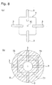
- Figure 8 illustrates a plan view of the tray shapes that the apparatus can accommodate in the first embodiment.
- Figure 9 is an operation of the roller moving mechanism in the first embodiment.
- Figure 10 is an operation of the roller moving mechanism in a variation on the first embodiment.
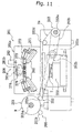
- Figure 11 is a traverse cross section of the packaging apparatus in the second embodiment.
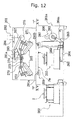
- Figure 12 is a longitudinal cross section packaging apparatus in the second embodiment.
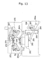
- Figure 13 illustrates the operation of the packaging apparatus in the second embodiment.
- Figure 14 illustrates the operation of the packaging apparatus in the second embodiment.
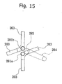
- Figure 15 is a planar arrangement of the rollers in the second embodiment (as viewed across a XV-XV line shown in Figure 12).
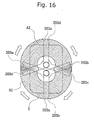
- Figure 16 is a planar path of the rollers resulting from swiveling in the second embodiment.
- Figure 17 is an enlarged view of the flange area when the rollers contact the tray in the second embodiment.
- Figure 18 is an enlarged view of the flange area when the film is thermally welded to the tray in the second embodiment.
- Figure 19 illustrates how the roller path changes when the swivel shafts are moved in the second embodiment.
- Figure 20 illustrates the operation of the rollers in the third embodiment.
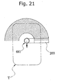
- Figure 21 illustrates the operation of the rollers in the third embodiment.
- Figure 22 illustrates the operation of the rollers in the third embodiment.
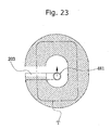
- Figure 23 illustrates the operation of the rollers in the third embodiment.
- Figure 24 illustrates the operation of the rollers in the third embodiment.
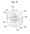
- Figure 25 is a plan view of the roller arrangement in the second and third embodiment.
- Figure 26 is a schematic view of the packaging apparatus in the fourth embodiment.
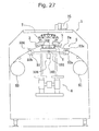
- Figure 27 is one state of the packaging apparatus in the fourth embodiment.
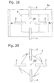
- Figure 28 is a plan view showing the arrangement of the tray and film in the fourth embodiment.
- Figure 29 is a rotational motion of tray in the fourth embodiment.
- FIG. 1 First embodiment of a packaging apparatus in accordance with the present invention is shown in FIG. 1.
- the packaging apparatus 1 shown in the figure is a so-called top-seal type packaging apparatus wherein the opening o on the upper portion of a tray T containing meat, fish, or other perishable food product is covered with a film Fm (see FIG. 6) and sealed by thermally welding film Fm to flange f, which is disposed around the periphery of opening o in tray T.
- a film Fm see FIG. 6
- Packaging apparatus 1 comprises chiefly the following components: a frame 1a; a holding member 2, which holds tray T; four rollers 3 positioned above holding member 2; a film feeding mechanism 5, which feeds film Fm between holding member 2 and rollers 3; a lift mechanism 6, which raises and lowers holding member 2; a roller moving mechanism 7, which moves rollers 3 chiefly up and down; a roller swivel mechanism 8, which swivels rollers 3; and a controller (not shown), which controls the mechanisms.
- Holding member 2 holds tray T on its upper surface and is raised and lowered by lift mechanism 6. Tray T may be placed on holding member 2 either manually by an operator or automatically by a separate transport apparatus.
- Each roller 3 comprises a cylindrical member that is axially supported by roller support 71 of roller moving mechanism 7 (discussed later) so that the roller can rotate freely.
- the surface of roller 3 is provided with a layer that is softer than other parts of the roller in order to reduce the frictional resistance between the roller and film Fm.
- the surface of roller 3 is made of a resilient material, such as resin or synthetic rubber, so that firm contact can be maintained between film Fm and flange f even when small irregularities exist on the surface of flange f of tray T. Also, since friction between roller 3 and film Fm is improved, roller 3 rolls surely and film Fm is sealed without occurrence of pinholes and other defective things. As shown in FIG.
- rollers 3 are arranged radially with respect to shaft 81 of roller swivel mechanism 8 (discussed later). As shown in FIG. 1, rollers 3 are supported by roller supports 71 in such a manner that, when viewed from the side, they form an angle with respect to the horizontal plane containing the upper face of tray T. The angle is set so that the end of each roller 3 that is closer to shaft 81 is higher than the other end.
- each roller 3 Inside each roller 3 is a heating element (not shown) for heating the roller 3.
- Appropriate specifications for the heating element are selected based on the materials from which the tray T and film Fm are made and the necessity of supplying energy that can quickly replenish the heat lost during the sealing operation.
- Film feeding mechanism 5 delivers an amount of film Fm that is appropriate for the size of tray T to the space between lowered holding member 2 and rollers 3.
- Film feeding mechanism 5 comprises a delivery section 51 which holds the supply of film Fm, a transport section which transports film Fm and is capable of clamping film Fm, and a take-up section 53 which takes up the film Fm remaining after a portion has been cut away to package tray T.
- Delivery section 51, the transport section, and take-up section 53 are each supported by frame la.
- the transport section comprises: transport rollers 52a, 52b disposed on opposite sides of the space between holding member 2 and rollers 3; presser rollers 52c, 52d that press against the transport rollers; two belts B1 that traverse transport rollers 52a, 52b; and two belts B2 that traverse presser rollers 52c, 52d.
- transport rollers 52a, 52b and take-up section 53 are operated using a motor or other driving means (not shown).
- the controller can instruct the transport section to adjust the amount of film it carries in order to accommodate the size of tray T.
- the data used to change the feed amount can be provided to the controller by manually entering the size of tray T in advance or by using a measuring device to detect the size tray T.
- the two belts B1 traversing transport rollers 52a, 52b and the two belts B2 traversing presser rollers 52c, 52d can move freely in a direction roughly perpendicular to the direction in which film Fm is fed (the film moves from left to right in FIG. 1).
- lift mechanism 6 discussed later raises tray T, these belts apply tension to film Fm, making it possible to achieve a smooth film surface with no wrinkles over opening o in tray T.
- Belts B1 which transport film Fm, are made of a material that grips onto film Fm and are structured so that the film can be sandwiched between belts B1 and the belts B2 traversing presser roller 52c, 52d.
- Lift mechanism 6 is a mechanism for lifting tray T against film Fm and comprises: a drive motor 61; stationary section 62, which is affixed to frame la; and moving section 63, which moves up and down with respect to stationary section 62.
- Holding member 2 is affixed to the upper face of moving section 63.
- a tray T placed on holding member 2 is raised and lowered according to the movement of moving section 63.
- Drive motor 61 is a servomotor or a stepper motor, and its speed is controlled electronically by the controller. Since the movement of moving section 63 is controlled electronically, this embodiment allows the speed curve, stroke, and other aspects of the movement to be set relatively easily, thus making it possible to raise and lower tray T under the conditions best suited to the size of tray T and the article being packaged. Additionally, mechanisms and control methods other than the electronic control described above can also be used to move moving section 63. Such mechanisms and control methods include mechanical control using cams and crank mechanisms and pneumatic control using air cylinders and the like.
- Roller moving mechanism 7 is a mechanism for changing the vertical position of rollers 3 and, as shown in FIGS. 1 and 9, comprises: roller supports 71, which axially support rollers 3; link mechanism 72; presser plate 73; lever mechanism 74, which applies a force to the upper side of presser plate 73; and motor 75, which operates lever mechanism 74.
- Roller supports 71 axially support rollers 3 in such a manner that rollers 3 are angled as shown in FIG. 1 when viewed from the side.
- One end of link mechanism 72 supports roller support 71 with a pin and the other end is pressed downward by presser plate 73.
- the other end of link mechanism 72 is pressed down by presser plate 73, the one end is raised as shown on the right side of FIG. 9.
- roller support 71 and roller 3 are also brought to a raised position.
- presser plate 73 no longer applies a force to link mechanism 72, the opposite end of link mechanism 72 moves down due to the weight of roller supports 71 and rollers 3 (see left side of FIG. 9).
- Presser plate 73 is a disk shaped member that can move freely up and down along shaft 81 of roller swivel mechanism 8 (discussed later).
- the force that moves presser plate 73 downward is provided from above by lever mechanism 74, which is driven by motor 75.
- the outer edge of presser plate 73 rests on the other end of link mechanism 72 (see FIG. 9).
- Roller swivel mechanism 8 swivels rollers 3, as well as the roller supports 71 and link mechanisms 72 that support them, through a prescribed angle when the package is being sealed and comprises shaft 81 and motor 82, which rotates shaft 81.
- the lower end of shaft 81 is fixed to base 79, which supports link mechanism 72, and the upper end of shaft 81 is fixed to connected to motor 82 via a timing belt and pulley (not shown).
- rollers 3 swivel about shaft 81 over the prescribed angle (see FIG. 5).
- the controller When a tray T is loaded onto holding member 2 as shown in FIG, 1, the controller first calculates the amount of film Fm to be fed by film feeding mechanism 5 based on the size of tray T that was detected by a measuring device or provided via manual input.
- the transport section moves the two belts B1 that traverse transport rollers 52a, 52b and the two belts B2 that traverse presser rollers 52c, 52d in a direction perpendicular to the transport direction (horizontal direction in FIG. 4).
- This movement of the belts stretches film Fm in the traverse direction (vertical direction in FIG. 4), thus tensioning film Fm in the traverse direction.
- Lift mechanism 6 then lifts moving section 63 by the amount calculated by the controller based on the size of tray T; tray T pushes film Fm upward and stops (see FIG. 2). The upward pressure of tray T tensions film Fm in the transport direction.
- controller controls motor 75 so as to release the downward force lever mechanism 74 applies to presser plate 73, thus releasing link mechanism 72.
- rollers 3 move into contact with tray T due to their own weight (see FIG. 3). Since rollers 3 are independent of one another, each roller 3 contacts tray T with roughly the same pressure.
- the controller While simultaneously controlling motor 75 so that rollers 3 contact tray T, the controller instructs motor 82 to rotate shaft 81 through a prescribed angle. Since four rollers 3 are provided at an even spacing with respect to the rotational direction (see FIG. 4), a prescribed angle of 90° would be sufficient for rollers 3 to seal the entire periphery of tray T. However, in this embodiment, a slightly larger angle of 100° is used.
- shaft 81 turns and rollers 3 begin to rotate (see FIG. 5)
- rollers 3 follow along the periphery (flange f) of tray T and thermally weld film Fm to tray T, thus forming a seal.
- rollers 3 roll on flange f as they move.
- FIG. 6 shows an enlarged view of the contact area between rollers 3 and tray T when the former move along the periphery of the latter.
- the opening o in tray T is covered by film Fm, which is tensioned in both the longitudinal and traverse directions, and film Fm is pressed against flange f of tray T.
- Rollers 3 touch diagonally against the portion where film Fm contacts flange f and apply both heat and pressure. This heal and pressure causes film Fm and flange f to thermally fuse together.
- film Fm melts and is cut away at the edge portion (which is, in this case, the apex of flange f where rollers 3 are touching) of tray T because the heat and pressure are concentrated on film Fm at the edge portion of tray T (see FIG. 7).
- rollers 3 After rollers 3 have finished sealing film Fm to tray T, rollers 3 are raised and lift mechanism 6 lowers tray T. Then the sealed tray T is removed from holding member 2 and the next cycle begins.
- film Fm of which a portion has been thermally cut away in the process of sealing tray T, is taken up by driving take-up section 53.
- the width Fh of film Fm is set to be wider than the width Th of tray T (see FIG. 4); the continuity of film Fm is not severed as a result of sealing tray T and trouble wherein it becomes impossible for take-up section 53 to take up the film does not occur.
- FIGS. 11 and 12 Second embodiment of a top-seal packaging apparatus in accordance with the present invention is shown in FIGS. 11 and 12.
- the packaging apparatus 201 shown in the figures is an apparatus wherein the opening o in the upper portion of a tray T containing meat, fish, or other perishable food product or a side dish or other processed food product is covered with a stretch film Fm (see FIG. 17) and sealed by thermally welding stretch film Fm to a flange (periphery of the opening) f, which is disposed around the periphery of opening o in tray T.
- Packaging apparatus 201 comprises the following components: a frame 201a; a tray-holding mechanism 202, which holds tray T; four rollers 203 positioned above tray-holding mechanism 202; a film transport mechanism 205, which feeds stretch film Fm between tray-holding mechanism 202 and rollers 203; a lift mechanism 206, which raises and lowers tray-holding mechanism 202; a roller ascent-descent mechanism 207, which moves rollers 203 chiefly up and down; a roller swivel mechanism 208 with two swivel shafts, which swivels rollers 203 around the swivel shafts 281a, 281b; a stretch mechanism 209, which stretches stretch film Fm in the space between tray-holding mechanism 202 and rollers 203; and a controller (not shown), which controls each of the mechanisms.
- Tray-holding mechanism 202 holds tray T on its upper surface and is raised and lowered by lift mechanism 206. As shown in FIG. 12, the tray-holding mechanism 202 can be drawn out to the position indicated with a double-dotted chain line or pushed in to the position indicated with a solid line by a slide mechanism. This horizontal movement is accomplished manually or by a drive means (not shown). The slide mechanism is supported by pins and can hand the tray-holding mechanism 202 to lift mechanism 206.
- Tray T may be placed on tray-holding mechanism 202 either manually by an operator or automatically by a separate transport apparatus.
- Each roller 203 comprises a cylindrical member that is axially supported by roller support 271 of roller ascent-descent mechanism 207 (discussed later) so that the roller can rotate freely.
- the surface of roller 203 is provided with a layer that is softer than other parts of the roller. More particularly, the surface of roller 203 is made of an elastomer, so that firm contact can be maintained between stretch film Fm and flange f even when small irregularities exist on the surface of flange f of tray T.
- the elastomer used is one that contains heat resistant silicon or fluoro rubber.
- rollers 203 reduces the chance that rollers 203 will damage the surface of tray T as they roll on the tray and reduces susceptibility to heat deterioration because the elastomer is highly heat resistant. Also, rollers 203 rolls surely and stretch film Fm is sealed without occurrence of pinholes and other defective things because the friction between roller 203 and film Fm is improved by using the elastomer. Such elastomers also provide good heat conduction and improve efficiency, and they reduce damage to the stretch film because of they improve surface release properties.
- FIG. 15 shows the arrangement of rollers 203 when viewed from underneath.
- rollers 203 are arranged as shown in FIG. 15 and are mounted to swivel shafts 281a, 281b at an angle of roughly 110°.
- FIG. 15 is a simplified figure and a planar arrangement of rollers 203.
- rollers 203 are supported by roller supports 271 in such a manner that, when viewed from the side, they form an angle with respect to the horizontal plane containing the upper face of tray T.
- the angle is set so that the end of each roller 203 that is closer to swivel shafts 281a, 281b is higher than the other end.
- each roller 203 Inside each roller 203 is a heating element (not shown) for heating the roller 203.
- Appropriate specifications for the heating element are selected based on the materials from which the tray T and stretch film Fm are made and the necessity of supplying energy that can quickly replenish the heat lost during the sealing operation.
- Film transport mechanism 205 delivers an amount of stretch film Fm that is appropriate for the size of tray T to the space between lowered tray-holding mechanism 202 and rollers 203. As shown in FIG. 11, film transport mechanism 205 comprises a film delivery section 251, a film transport section 252, and a film take-up section 253. Film delivery section 251, film transport section 252, and film take-up section 253 are each supported by frame 201a.
- the film delivery section 251 serves as the supply source of stretch film Fm and comprises members that rotatably support film roll R of stretch film Fm.
- Stretch film delivery section 251 has a core support member 251a, which can move up and down, and a support roller 251b, which supports film roll R at an angle from underneath. Film roll R is supported (see FIG. 11) by core support member 251a, support roller 251b, and delivery roller 252a of film transport section 252 (discussed later).
- the film take-up section 253 has a take-up shaft 253a and is provided to take up the stretch film Fm that remains after a portion has been cut away to package (top-seal) tray T.
- Take-up shaft 253a is rotated by belt 253b, which is connected to motor 252c (discussed later).
- the film transport section 252 is provided with: delivery roller 252a; motor 252c, which rotates delivery roller 252a via belt 252b; and film support roller 252d.
- the stretch film Fm taken from film roll R is fed toward film take-up section 253 by the rotation of delivery roller 252a.
- Film delivery roller 252a and support roller 251b are disposed symmetrically with respect to core support member 251a.
- the distance between delivery roller 252a and support roller 251b is set to be smaller than the diameter of the core of film roll R.
- These rollers 252a, 251b prevent film roll R from dropping down.
- Film support roller 252d is positioned close to film take-up roller 253 and its height is set so that its upper surface is aligned with the lower surface of delivery roller 252a (see FIG. 11).
- Stretch mechanism 209 grips both sides of stretch film Fm, which runs from film delivery section 251 to film take-up section 253, in the horizontal section between delivery roller 252a and film support roller 252d and stretches stretch film Fm in the traverse direction (horizontal direction in FIG. 12).
- Stretch mechanism 209 is provided with a pair of film grippers 291a, 291b extending in the film transport direction and a stretch drive section (not shown), which moves the grippers perpendicularly (horizontal direction in FIG. 12) to the film transport direction.
- Film grippers 291a, 291b comprise a mechanism that grips stretch film Fm by sandwiching it from the top and bottom and are turned ON and OFF using a solenoid. Slippage between film grippers 291a, 291b and stretch film Fm is prevented by mounting a rubber (or resin) pad having a large coefficient of friction on the part that contacts the upper side of stretch film Fm.
- the stretch drive section comprises a guide rail, a motor, a sprocket, a chain, etc, and moves film grippers 291a, 291b to the left and right (when viewed as shown in FIG. 12) in response to instructions from the controller.
- Lift mechanism 206 is a mechanism for lifting tray-holding mechanism 202, while the same holds a tray T, against stretch film Fm, as shown in FIG. 13.
- Lift mechanism 206 comprises: a drive motor 261; large gear 262, which is axially supported by frame 201a; link member 263; lever 264, one end of which is axially supported by frame 201a at support point 264a; disk member 265, which is rotatably mounted to the end of lever 264; etc.
- tray-holding mechanism 202 moves up or down (see FIGS. 12 and 13) because its underside is supported by disk member 265. Also, tray support mechanism 202 is guided by vertical guide rails 269 and moves in the vertical direction in response to the operation of lift mechanism 206.
- Roller ascent-descent mechanism 207 is a mechanism for changing the vertical position of rollers 203 and, as shown in FIG. 11, comprises: roller supports 271, which axially support rollers 203; link mechanism 272; presser plate 273; lever mechanism 274, which applies a force to the upper side of presser plate 273; and motor 275, which operates lever mechanism 274.
- Roller supports 271 axially support rollers 203 in such a manner that rollers 203 are angled as shown in FIGS. 11 and 12 when viewed from the side.
- the rotational axis of each roller 203 is indicated in FIGS. 11 and 12 by a single-dotted chain line passing through the roller 203.
- One end of link mechanism 272 supports roller support 271 with a pin and the other end is pressed downward by presser plate 273.
- presser plate 273 When the other end of link mechanism 272 is pressed down by presser plate 273, the one end is raised as shown in FIGS. 11 and 12.
- roller support 271 and roller 203 are also brought to a raised position.
- presser plate 273 no longer applies a force to link mechanism 272
- the opposite end of link mechanism 272 moves down due to the weight of roller support 271 and roller 203 (see FIGS. 12 and 14).
- presser plate 273 The force that moves presser plate 273 is provided from above by lever mechanism 274, which is driven by motor 275.
- the outer edge of presser plate 273 rests on a rolling member axially supported on the other end of link mechanism 272 (see FIG. 19).
- Roller swivel mechanism 208 swivels rollers 203, as well as the roller supports 271 and link mechanisms 272 that support them, through a prescribed angle when the package is being sealed.
- Roller swivel mechanism 208 comprises chiefly: a first swivel shaft 281a; a second swivel shaft 281b; and a motor 282, which rotates both swivel shafts 281a, 281b.
- first swivel shaft 281a is fixed to a base 279, which supports two of link mechanisms 272, and the upper end is meshed with main gear 283 via a gear.
- Main gear 283 is connected to motor 282 by a pulley and a belt 284 and rotates when motor 282 operates.
- second swivel shaft 281b is fixed to a separate base 279 (a separate member from the base 279 to which first swivel shaft 281a is fixed), which supports the other two link mechanisms 272.
- the upper end of second swivel shaft 281b is meshed with main gear 283 via a gear (see FIG. 15).
- each roller 203 revolves through the prescribed angle about first swivel shaft 281a or second swivel shaft 281b (see FIG. 16).
- first swivel shaft 281a or second swivel shaft 281b
- rollers 203 linked to first swivel shaft 281a are indicated as roller 203a and roller 203b
- rollers 203 linked to second swivel shaft 281b are indicated as roller 203c and roller 203d.
- the positions of rollers 203 before swiveling are indicated with solid lines and the positions of rollers 203 after swiveling are indicated with dotted lines.
- tray-holding mechanism 202 Once a tray T containing a food product or other article is loaded onto tray-holding mechanism 202, which has been drawn out to the position indicated with a double-dotted chain line in FIG. 12, tray-holding mechanism 202 is moved horizontally under rollers 203 by hand or using a driving means not shown.
- tray-holding mechanism 202 After tray-holding mechanism 202 has moved underneath rollers 203, multiple holding members push against the sides of tray T and position tray T, thus holding tray T so that tray T is prevented from moving out of place.
- tray T when tray T is loaded onto tray-holding mechanism 202, a camera (not shown) detects the size of tray T and sends the size data to the controller.
- the controller Based on the size of tray T, the controller identifies the type of tray T and calculates the amount of stretch film Fm to be fed by film transport mechanism 205.
- the controller When the film transport mechanism 205 has fed the calculated amount of stretch film Fm, the controller operates stretch mechanism 209 to stretch stretch film Fm in the traverse direction (horizontal direction in FIG. 12). As a result, stretch film Fm is tensioned in the traverse direction and has no wrinkles.
- controller operates lift mechanism 206 and lifts tray-holding mechanism 202, which is holding tray T. Tray T pushes stretch film Fm upward and stops (see FIG. 13).
- rollers 203 move down into contact with tray T due to their own weight (see FIG. 14). Since rollers 203 are independent of one another, each roller 203 contacts tray T with roughly the same pressure.
- the controller instructs motor 282 to rotate swivel shafts 281 through a prescribed angle.
- the prescribed angle is set so that the entire flange f of tray T will be sealed by one of rollers 203a through 203d; in this embodiment, an angle of 110° is used (see FIG. 16).
- rollers 203 When rollers 203 are swiveled about swivel shafts 281a, 281b and begin to roll over the stretch film Fm on tray T, rollers 203 thermally weld stretch film Fm to flange f of tray T.
- FIG. 17 shows an enlarged view of the contact area between rollers 203 and tray T when the former move along the periphery of the latter.
- the opening o of tray T is covered by stretch film Fm, and stretch film Fm is pressed against flange f of tray T.
- Rollers 203 touch diagonally against the portion where stretch film Fm contacts flange f and apply both heat and pressure. This heat and pressure causes stretch film Fm and flange f to thermally fuse together.
- stretch film Fm melts and is cut away at the edge portion (which is, in this case, a portion to the outside of the apex of flange f where rollers 203 are touching) of tray T because the heat and pressure are concentrated on stretch film Fm at the edge portion of tray T (see FIG. 18).
- the controller swivels rollers 203 at a speed that allows the stretch film to be thermally cut along the outside of the portion bonded by thermal welding while stretch film Fm is being thermally welded to flange f.
- rollers 203 After rollers 203 have finished sealing stretch film Fm to tray T, rollers 203 are raised and tray T is lowered. Then the sealed tray T is removed from drawn out tray-holding mechanism 202 and the next cycle begins.
- stretch film Fm of which a portion has been thermally cut away in the process of sealing tray T, is wound onto take-up shaft 253a.
- motor 252c rotates film support roller 252d and delivery roller 252a so that the stretch film Fm for the next cycle is fed (supplied to the area below rollers 203) simultaneously with the taking up of the cut film.
- the width of stretch film Fm is selected so that the width of the film will be exceed the width of tray T when the film is stretched by stretch mechanism 209.
- the continuity of stretch film Fm is not severed as a result of sealing tray T (i.e., cutting a hole in stretch film Fm) and trouble wherein it becomes impossible for film take-up section 253 to take up the film does not occur.
- both swivel shafts 281a, 281b are fixed, but the range of applicable sizes and shapes of tray could be increased even further by making one or both shafts movable.
- swivel shafts 281a, 281b are replaced with swivel shafts 381a, 381b, which are planarly moveable in the film transport direction (the vertical direction in FIG. 19), and rollers 203 are connected to swivel shafts 381a, 381b.
- Swivel shafts 381a, 381b are moved planarly by an electric powered ball screw mechanism and crank mechanism based on instructions from the controller.
- a large-sized tray T that extends outside swivel area A3 of rollers 203a through 203d when the distance between swivel shafts 381a, 381b is S1 can be successfully heat sealed by moving swivel shafts 381a, 381b so that the distance between them increases to S2, as shown in FIG. 19(b), and thus expanding the swivel area of rollers 203a through 203d from A3 to A4.
- the positioning of rollers 203 before swiveling is indicated with solid lines and the positioning of rollers 203 after swiveling is indicated with dotted lines.
- the amount of time rollers 203 are in contact with each portion of flange f of tray T can be brought closer to a fixed value (optimum value).
- the movement area of rollers 203 is expanded by providing roller swivel mechanism 208 with two swivel shafts 281a, 281b.
- This embodiment adopts a configuration wherein single swivel shaft 481 is moved in the longitudinal direction of tray T (vertical direction in FIG. 20) using a moving mechanism (not shown).
- One roller 203 is connected to swivel shaft 481 using a base member and a link mechanism.
- roller 203 swivels around swivel shaft 481 when swivel shaft 481 rotates.
- roller 203 swivels, moving from the state shown in FIG. 20 to the state shown in FIG. 21.
- the shaded area in FIG. 21 indicates the path of roller 203.
- the stretch film is thermally welded to the portion of the flange of tray T located in this area during the stage of the sealing process illustrated in FIG. 21.
- roller 203 also moves horizontally from the state shown in FIG. 21 to the state shown in FIG. 22. This movement results in the stretch film being thermally welded to the middle portion of one of the long sides of tray T.
- the controller then rotates swivel shaft 481 180°, causing roller 203 to move from the state shown in FIG. 22 to the state shown in FIG. 23.
- swivel shaft 481 is moved horizontally back to its original position (see FIG. 24) and roller 203 completes a path around the entire flange of tray T.
- the stretch film is thermally welded so that the opening in tray T is sealed.
- this embodiment of the packaging apparatus is provided with a moving mechanism that moves swivel shaft 481 planarly.
- roller 203 is moved over the entire flange of the tray by moving swivel shaft 481.
- the entire flange can be accommodated even when the tray is of a shape (or size) that roller 203 cannot follow using swiveling alone, that is, a tray that extends outside the path of roller 203 (i.e., the movement area of roller 203) when swiveling alone is used.
- the amount of time roller 203 touches each portion of the flange of the tray can be made more uniform by moving roller 203 using a combination of swiveling and planar motion.
- the amount of time roller 203 touches each portion of the flange of the tray can be brought even closer to a fixed value by controlling the swivel speed and the planar motion speed.
- the amount of time roller 203 touches each portion of the flange of the tray can be made uniform by controlling the apparatus so that swivel shaft 481 remains planarly immobile.
- a tray rotation mechanism 108 is replaced with the roller swivel mechanism as shown in FIGS. 26 and 27. Therefore, rollers 3 do not swivel. But the roller moving mechanism 7 changes the vertical position of rollers 3.
- Tray rotation mechanism 108 comprises shaft 181 and motor 182, which rotates shaft 181.
- the upper end of shaft 181 fixed to a tray-holding mechanism 102, which holds tray T.
- the lower end of shaft 181 is connected to motor 182.
- the tray-holding mechanism 102 rotates.
- the controller controls rotation of motor 182.
- Motor 182 fixed to a moving portion 63 of lift mechanism 6 (see FIG. 26 and 27).
- Tray-holding mechanism 102 holds tray T on its upper surface. Tray-holding mechanism 102 also holds the sides of tray T so that tray T is prevented from moving out of place, especially rotating. Tray-holding mechanism 102 has four side-holding members 102a pushing against the sides of tray T and prevent from moving as shown in FIG. 26.
- film feeding mechanism 5 feeds film Fm.
- the two belts B1 that traverse transport rollers 52a, 52b and the two belts B2 that traverse presser rollers 52c, 52d are moved in a direction perpendicular to the transport direction (horizontal direction in FIG. 28). This movement of the belts stretches film Fm in the traverse direction (vertical direction in FIG. 28), thus tensioning film Fm in the traverse direction.
- Lift mechanism 6 then lifts moving section 63 by the amount calculated by the controller based on the size of tray T; tray T pushes film Fm upward and stops. The upward pressure of tray T tensions film Fm in the transport direction.
- controller controls motor 75 so as to release the downward force lever mechanism 74 applies to presser plate 73, thus releasing link mechanism 72.
- rollers 3 move into contact with tray T due to their own weight (see FIG. 27). Since rollers 3 are independent of one another, each roller 3 contacts tray T with roughly the same pressure.
- the controller instructs motor 182 of tray rotation mechanism 108 to rotate shaft 181 through a prescribed angle. Since four rollers 3 are provided at an even spacing with respect to the rotational direction (see FIG. 28), a prescribed angle of 90° would be sufficient for rollers 3 to seal the entire periphery of tray T. However, in this embodiment, a slightly larger angle of 100° is used.
- shaft 181 turns and rollers 3 begin to rotate (see FIG. 29)
- rollers 3 follow along the periphery (flange f) of tray T and thermally weld film Fm to tray T, thus forming a seal.
- rollers 3 roll on flange f as they move on account of rotation of tray T.
- rollers 3 After rollers 3 have finished sealing film Fm to tray T, rollers 3 are raised and lift mechanism 6 lowers tray T. Then the sealed tray T is removed from tray rotation mechanism 108 and the next cycle begins.
- film Fm of which a portion has been thermally cut away in the process of sealing tray T, is taken up by driving take-up section 53.
- the width Fh of film Fm is set to be wider than the width Th of tray T (see FIG. 28); the continuity of film Fm is not severed as a result of sealing tray T and trouble wherein it becomes impossible for take-up section 53 to take up the film does not occur.
- tray is rotated against rollers in the fourth embodiment and rollers are swiveled against tray in the first embodiment, it is also acceptable to rotate the tray and swivel rollers simultaneously.
- the hot member since the hot member is applied at an angle to the flange, the hot member does not come in contact with a portion of the film covering the opening. Consequently, the portion of the film that covers the opening is less likely to melt or develop tiny holes.
Landscapes
- Engineering & Computer Science (AREA)
- Mechanical Engineering (AREA)
- Closing Of Containers (AREA)
- Package Closures (AREA)
- Basic Packing Technique (AREA)
Abstract
Description
Claims (19)
- A packaging method comprising:a first step of putting an article to be packaged on a tray having an opening in its upper face;a second step of covering the opening in the tray with a film;a third step of touching, in a direction intersecting with a vertical direction, a heated hot member against the film on a portion of the tray near the opening where the film touches; anda fourth step of moving at least one of the hot member or the tray.
- A packaging method set forth in claim 1, wherein:either one or two or more hot members are touched against the film on a portion of the tray near the opening in the third step; andsaid hot members move along the periphery of the opening in the tray in the fourth step.
- A packaging method set forth in any one of claim 1 or 2, wherein, during the third and fourth steps, the hot member not only thermally welds the film to a portion of the tray near the opening but also cuts the outer portion of the thermally welded film.
- A packaging method set forth in any one of claims 1 through 3, wherein, during the fourth step, the hot member rolls as it moves along the periphery of the opening in the tray.
- A packaging method set forth in any one of claims 1 through 4, wherein, during the fourth step, the hot member is moved along the periphery of the opening in the tray by swiveling the hot member about a swivel shaft while planarly moving the swivel shaft.
- A packaging method set forth in any one of claims 1 through 5, wherein:during the third step, a plurality of the hot members are touched against the periphery of the opening in the tray; andduring the fourth step, the hot members are moved along the periphery of the opening in the tray by swiveling the plurality of hot members about the axes of at least two swivel shafts disposed in different planar positions.
- A packaging apparatus, wherein a tray, provided with a flange and an opening surrounded by said flange on its upper face and containing an article to be packaged, is covered with a film over the opening and the film is welded to the flange, the packaging apparatus comprising:a hot member capable of touching against the film on a portion of the flange of the tray and for which the face capable of touching the tray is at an angle with respect to a horizontal plane; anda moving means for moving at least one of the hot member or the tray.
- A packaging apparatus set forth in claim 7, wherein, the moving means moves the hot member against the tray.
- A packaging apparatus set forth in claim 8, wherein, the moving means comprising:a swivel mechanism which swivels the hot member about a swivel shaft; anda moving swivel shaft mechanism which planarly moves the swivel shaft of the swivel mechanism.
- A packaging apparatus set forth in claim 9, further comprising:
a controller controls at least one of the speed at which the hot member is swiveled by the swivel mechanism or the speed at which the swivel shaft is moved by the moving swivel shaft mechanism. - A packaging apparatus set forth in claim 8, wherein:a plurality of said hot members are provided;the swivel mechanism has at least two swivel shafts disposed in different planar positions, which moves the plurality of hot members by swiveling at least one of the hot members about a first swivel shaft and swiveling at least one of the hot members about a second swivel shaft.
- A packaging apparatus set forth in claim 11, further comprising:
a moving swivel shaft mechanism which planarly moves at least one of swivel shafts. - A packaging apparatus set forth in claim 12, further comprising:
a controller controls at least one of the speed at which the hot member is swiveled by the swivel mechanism or the speed at which the swivel shaft is moved by the moving swivel shaft mechanism. - A packaging apparatus set forth in claim 7, wherein, the moving means moves the tray against the hot member.
- A packaging apparatus set forth in any one of claims 7 through 14, further comprising:a film feeding means for feeding the film between the tray and the hot member;a lift mechanism which lifts the tray and presses the flange of the tray against the film; anda hot member moving mechanism which moves the hot member and presses it against the film at a portion of the flange of the tray, which has been lifted by said lift mechanism.
- A packaging apparatus set forth in any one of claims 7 through 15, wherein a plurality of said hot members are provided and so arranged that each hot member can touch a different portion of the flange of the tray.
- A packaging apparatus set forth in any one of claims 7 through 16, further comprising:
a controller controls the moving means to move at least one of the tray or the hot member so that the film is thermally cut at the outside of the thermally welded portion while being thermally welded to the tray. - A packaging apparatus set forth in any one of claims 7 through 17, wherein the hot member is a heat-emitting roller and rolls on the flange of the tray while the tray and the hot member are moving relative to each other.
- A packaging apparatus set forth in any one of claims 7 through 18, wherein the part of the hot member that touches the periphery of the opening in the tray is made of an elastomer containing silicon or fluoro rubber.
Applications Claiming Priority (5)
| Application Number | Priority Date | Filing Date | Title |
|---|---|---|---|
| JP13702599 | 1999-05-18 | ||
| JP13702599 | 1999-05-18 | ||
| JP2000113549 | 2000-04-14 | ||
| JP2000113549 | 2000-04-14 | ||
| PCT/JP2000/003021 WO2000069725A1 (en) | 1999-05-18 | 2000-05-10 | Packaging method and packaging apparatus |
Publications (2)
| Publication Number | Publication Date |
|---|---|
| EP1114777A1 true EP1114777A1 (en) | 2001-07-11 |
| EP1114777A4 EP1114777A4 (en) | 2006-04-19 |
Family
ID=26470458
Family Applications (1)
| Application Number | Title | Priority Date | Filing Date |
|---|---|---|---|
| EP00925623A Withdrawn EP1114777A4 (en) | 1999-05-18 | 2000-05-10 | Packaging method and packaging apparatus |
Country Status (5)
| Country | Link |
|---|---|
| US (1) | US6666005B1 (en) |
| EP (1) | EP1114777A4 (en) |
| KR (1) | KR20010052466A (en) |
| TW (1) | TW464629B (en) |
| WO (1) | WO2000069725A1 (en) |
Families Citing this family (20)
| Publication number | Priority date | Publication date | Assignee | Title |
|---|---|---|---|---|
| NZ516089A (en) * | 2000-04-14 | 2003-04-29 | Ishida Scale Mfg Co Ltd | Device and method for top seal packaging |
| JP2002068139A (en) * | 2000-08-30 | 2002-03-08 | Nissei Maryland Cup Kk | Container sealing method and sealing device |
| JP2002160701A (en) * | 2000-11-22 | 2002-06-04 | Ishida Co Ltd | Packaging equipment |
| JP2002160707A (en) * | 2000-11-24 | 2002-06-04 | Ishida Co Ltd | Measuring and packaging apparatus and measuring and packaging method |
| JP2002160703A (en) * | 2000-11-24 | 2002-06-04 | Ishida Co Ltd | Packaging equipment |
| JP2002234503A (en) * | 2001-02-09 | 2002-08-20 | Ishida Co Ltd | Packaging equipment |
| JP4988109B2 (en) * | 2001-09-18 | 2012-08-01 | 株式会社イシダ | Packaging equipment |
| DE10321687A1 (en) * | 2003-05-14 | 2004-12-02 | Checkpoint Systems International Gmbh | Method and device for securing objects by strapping |
| JP2007008583A (en) * | 2005-06-01 | 2007-01-18 | Ishida Co Ltd | Packaging system |
| JP3193728U (en) * | 2014-08-06 | 2014-10-16 | 株式会社イシダ | Stretch wrapping machine |
| JP6235497B2 (en) * | 2015-01-22 | 2017-11-22 | 株式会社イシダ | Packaging equipment |
| JP6059747B2 (en) * | 2015-02-09 | 2017-01-11 | 株式会社イシダ | Stretch wrapping machine |
| DE102016105778A1 (en) * | 2016-03-30 | 2017-10-05 | Hamba Filltec Gmbh & Co. Kg | Device for filling food |
| CA3105935A1 (en) * | 2018-07-10 | 2020-01-16 | Maxima S.R.L. | Device for loading rolls on a machine and a machine comprising said device |
| DE102019219062A1 (en) * | 2019-12-06 | 2021-06-10 | Multivac Sepp Haggenmüller Se & Co. Kg | PACKAGING MACHINE AND PROCESS WITH FOLDER FUNCTION |
| EP4201824B1 (en) * | 2021-12-27 | 2026-01-28 | Bizerba SE & Co. KG | Packaging machine and method for packaging with stretch film |
| TWI806655B (en) * | 2022-06-13 | 2023-06-21 | 造葆有限公司 | Cutter structure of packaging machine and packaging bag manufactured thereby |
| DE102023112514A1 (en) | 2023-05-11 | 2024-11-14 | Multivac Sepp Haggenmüller Se & Co. Kg | Method and station for sealing a lidding film to a packaging tray |
| CN119460326A (en) * | 2025-01-14 | 2025-02-18 | 江苏智慧工场技术研究院有限公司 | Food packaging film sealing machine |
| CN119911479B (en) * | 2025-04-07 | 2025-06-20 | 远东中乾(厦门)科技集团股份公司 | Paper tableware tectorial membrane device |
Family Cites Families (19)
| Publication number | Priority date | Publication date | Assignee | Title |
|---|---|---|---|---|
| BE637703A (en) * | ||||
| JPS3614389B1 (en) * | 1959-03-12 | 1961-08-25 | ||
| US3508376A (en) * | 1964-05-12 | 1970-04-28 | Robert P Bemiss | Heat sealing of plastic trays |
| US3416292A (en) * | 1964-08-18 | 1968-12-17 | Reynolds Metals Co | Apparatus for making covered receptacles or the like |
| US3383256A (en) * | 1964-09-14 | 1968-05-14 | Dow Chemical Co | Process and apparatus for capping plastic containers |
| US3706175A (en) * | 1969-10-31 | 1972-12-19 | Ralph F Anderson | Method and apparatus for closing containers |
| BR7707256A (en) * | 1977-10-31 | 1979-05-29 | E Rondelli | MACHINE FOR CLOSING PACKAGES CONTAINING READY MEALS |
| US4162599A (en) * | 1978-06-19 | 1979-07-31 | C. A. Pemberton & Co. Limited | Vacuum packaging |
| JPS57110002A (en) | 1980-12-24 | 1982-07-08 | Hitachi Ltd | Power factor improving device for electric motor vehicle |
| JPS57110002U (en) * | 1980-12-26 | 1982-07-07 | ||
| JPH01130901A (en) | 1987-11-17 | 1989-05-23 | Ishida Iron Works Co Ltd | Push-up device for band sawing machine and setting usage thereof |
| JPH0744562Y2 (en) * | 1988-03-01 | 1995-10-11 | プリマハム株式会社 | Heat-sealing device for tray with rounded corners and heat-sealing surface |
| US4870800A (en) * | 1988-04-05 | 1989-10-03 | Nikka Co., Ltd. | Inert gas-filling and sealing device, heat sealing device and packaging apparatus using these devices |
| US5243808A (en) * | 1992-09-01 | 1993-09-14 | Kliklok Corporation | Flanged carton sealing apparatus and method |
| CH687609A5 (en) * | 1993-01-20 | 1997-01-15 | Tetra Alfa Holdings | Method and apparatus for filling and sealing of a package. |
| US5348752A (en) * | 1993-05-20 | 1994-09-20 | World Class Packaging Systems, Inc. | Dual state food packaging |
| JPH07285522A (en) * | 1994-02-28 | 1995-10-31 | Ntn Corp | Roller for continuous heat-sealing device |
| US5718101A (en) * | 1996-06-04 | 1998-02-17 | W. R. Grace & Co.-Conn. | Method and apparatus for packaging a product in a dual-lid package |
| US6050055A (en) * | 1998-08-21 | 2000-04-18 | Westvaco Corporation | Apparatus and method for sealing of paperboard containers using induction heated metal bands |
-
2000
- 2000-05-10 KR KR1020007013529A patent/KR20010052466A/en not_active Withdrawn
- 2000-05-10 WO PCT/JP2000/003021 patent/WO2000069725A1/en not_active Ceased
- 2000-05-10 EP EP00925623A patent/EP1114777A4/en not_active Withdrawn
- 2000-05-10 US US09/743,505 patent/US6666005B1/en not_active Expired - Fee Related
- 2000-05-12 TW TW089109177A patent/TW464629B/en not_active IP Right Cessation
Also Published As
| Publication number | Publication date |
|---|---|
| US6666005B1 (en) | 2003-12-23 |
| TW464629B (en) | 2001-11-21 |
| EP1114777A4 (en) | 2006-04-19 |
| WO2000069725A1 (en) | 2000-11-23 |
| KR20010052466A (en) | 2001-06-25 |
Similar Documents
| Publication | Publication Date | Title |
|---|---|---|
| US6666005B1 (en) | Packaging method and packaging apparatus | |
| EP3984730B1 (en) | Device and method for producing unvulcanized ring-shaped rubber member | |
| CA2780804C (en) | Machine for packaging products with stretchable and heat-weldable film | |
| KR100423589B1 (en) | Device and method for top seal packaging | |
| KR102384135B1 (en) | Film transporting device, film transporting method and resin molding device | |
| US6688082B1 (en) | Method for stopping and starting an automatic machine for collectively wrapping products, especially rolls of toilet or kitchen paper | |
| HK1037998A (en) | Packaging method and packaging apparatus | |
| JP2016097975A (en) | Band winding device of container | |
| JP7383294B2 (en) | Carrier tape thermocompression bonding device, carrier tape thermocompression bonding device system, and carrier tape thermocompression bonding method | |
| JPWO2000069725A1 (en) | Packaging method and packaging device | |
| JP2543818B2 (en) | Full web type automatic stretch wrapping machine | |
| JP2005088957A (en) | Film packaging apparatus | |
| JP3291243B2 (en) | Sheet transport accumulator | |
| JP3990351B2 (en) | Roll food packaging equipment | |
| JPH052404Y2 (en) | ||
| JPH052403Y2 (en) | ||
| JP2587503B2 (en) | Method and apparatus for attaching film lid to container | |
| JP2634986B2 (en) | Positioning device before trimming molded products | |
| JP2001328608A (en) | Top seal type packaging equipment | |
| WO2016117635A1 (en) | Transport device | |
| JPH1129111A (en) | Packaging equipment and packaging method | |
| JPH0454890Y2 (en) | ||
| JP2001301703A (en) | Top seal type packaging device and top seal type packaging method | |
| JP2003081204A (en) | Packaging device and packaging method | |
| JPH01279012A (en) | Discharge apparatus in packer |
Legal Events
| Date | Code | Title | Description |
|---|---|---|---|
| PUAI | Public reference made under article 153(3) epc to a published international application that has entered the european phase |
Free format text: ORIGINAL CODE: 0009012 |
|
| 17P | Request for examination filed |
Effective date: 20010308 |
|
| AK | Designated contracting states |
Kind code of ref document: A1 Designated state(s): AT BE CH CY DE DK ES FI FR GB GR IE IT LI LU MC NL PT SE |
|
| A4 | Supplementary search report drawn up and despatched |
Effective date: 20060307 |
|
| STAA | Information on the status of an ep patent application or granted ep patent |
Free format text: STATUS: THE APPLICATION IS DEEMED TO BE WITHDRAWN |
|
| 18D | Application deemed to be withdrawn |
Effective date: 20061027 |
|
| REG | Reference to a national code |
Ref country code: HK Ref legal event code: WD Ref document number: 1037998 Country of ref document: HK |