EP1114682B1 - Straightening machine with obliquely mounted rolls - Google Patents
Straightening machine with obliquely mounted rolls Download PDFInfo
- Publication number
- EP1114682B1 EP1114682B1 EP00125182A EP00125182A EP1114682B1 EP 1114682 B1 EP1114682 B1 EP 1114682B1 EP 00125182 A EP00125182 A EP 00125182A EP 00125182 A EP00125182 A EP 00125182A EP 1114682 B1 EP1114682 B1 EP 1114682B1
- Authority
- EP
- European Patent Office
- Prior art keywords
- piston
- cylinder unit
- straightening machine
- roll
- chock
- Prior art date
- Legal status (The legal status is an assumption and is not a legal conclusion. Google has not performed a legal analysis and makes no representation as to the accuracy of the status listed.)
- Expired - Lifetime
Links
- 230000008094 contradictory effect Effects 0.000 description 2
- 238000009434 installation Methods 0.000 description 2
- 241000237858 Gastropoda Species 0.000 description 1
- 241000256251 Spodoptera frugiperda Species 0.000 description 1
- 230000000295 complement effect Effects 0.000 description 1
- 230000000694 effects Effects 0.000 description 1
- 238000005516 engineering process Methods 0.000 description 1
- 230000036316 preload Effects 0.000 description 1
- 238000005096 rolling process Methods 0.000 description 1
Images


Classifications
-
- B—PERFORMING OPERATIONS; TRANSPORTING
- B21—MECHANICAL METAL-WORKING WITHOUT ESSENTIALLY REMOVING MATERIAL; PUNCHING METAL
- B21D—WORKING OR PROCESSING OF SHEET METAL OR METAL TUBES, RODS OR PROFILES WITHOUT ESSENTIALLY REMOVING MATERIAL; PUNCHING METAL
- B21D3/00—Straightening or restoring form of metal rods, metal tubes, metal profiles, or specific articles made therefrom, whether or not in combination with sheet metal parts
- B21D3/02—Straightening or restoring form of metal rods, metal tubes, metal profiles, or specific articles made therefrom, whether or not in combination with sheet metal parts by rollers
- B21D3/04—Straightening or restoring form of metal rods, metal tubes, metal profiles, or specific articles made therefrom, whether or not in combination with sheet metal parts by rollers arranged on axes skew to the path of the work
Definitions
- the invention relates to a cross roll straightening machine, consisting of a formed by a lower yoke, an upper yoke and columns connecting them Frame that receives rotatably mounted rollers in roller mills, the Roll mill of the lower roll in the Unterjoch and the roll mill of an adjusting spindle acted upon upper roller vertically adjustable in the upper yoke and the rollers for setting the crossing angle of the roller axes are pivotally mounted about a vertical center axis.
- Such an oblique roller straightening machine is, for example, designed by DE 19 10 879 became known.
- the roller mill For straightening so-called blank material (drawn or peeled Round bars) is the roller mill that supports the lower roller directly from the lower beam supported by the frame.
- black material unprocessed rolling rods with a not completely round cross-section
- the piston-cylinder unit on the other hand, can be acted upon with adjustable pressure, with which the Slide the lower roller with the roller mill from the support on the lower beam and the resilient support of the lower roller takes over.
- the roll or straightening nip can run out of a rod to be straightened Pressure relief of the piston-cylinder unit can be opened.
- the flexible support provides overload protection.
- the invention is therefore based on the object in a cross-roll straightening machine the type mentioned above means for guiding the chock to provide for the pillars of the frame, despite the contradictory demands allow both blank material and black material to be straightened.
- the top roller in one Installation piece is arranged, which is integrated with four guide surfaces between Setting wedges, fitting strips or similar guide means having adjusting means is guided on the columns of the frame, of which on the in the direction of flow of the leveling material seen front and rear frame pillars each Hydraulic guide wedge of a double-acting piston-cylinder unit and the other wedge is mechanically adjustable, and further the chock is formed with a hollow pin for guidance in the Oberjoch is that with a threaded nut for vertical adjustment of the chock is provided by means of a threaded spindle, the adjusting spindle on the upper yoke a double-acting clamping-piston-cylinder unit is assigned.
- By moving the Wedges are additionally reduced the guide play of the chock to zero mm. In this way, operationally reliable blank material straightening operation can be maintained.
- the clamping piston-cylinder unit of the adjusting spindle is at maximum pressure and the piston-cylinder units the hydraulic wedges are depressurized. So judging is also of blank material without activated clamping of our management level, i.e. with low set play, possible.
- the invention offers the possibility of an alternative control such that a straightening gap height set smaller than the current straightening material diameter of the rollers, the tensioning piston-cylinder unit for floating support of the Spindle is loaded and the piston-cylinder units of the hydraulically moved Wedges are depressurized.
- This allows the requirements for Straightening of black material also create, it is the incoming straightening material by the one set X smaller than the current target diameter Alignment gap height is enabled, the set alignment gap height by the amount X to press because the clamping piston-cylinder unit in the cylinder with a Gap applied according to the way of retreating or evading is.
- the cylinder can thus "float" around this dimension X and to compensate for the shape deviation of the target diameter.
- the chock is only subject to mechanical adjustable wedges set by means of stop screws.
- One according to an embodiment of the invention in the pressure side of the pressure medium supply adjustable pressure relief valve arranged in the clamping piston-cylinder unit ensures that it is possible to avoid the straightening force.
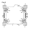
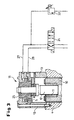
- a cross-roll straightening machine 1 shown in FIG. 1 has one of four guide columns 2 existing, a lower yoke 3 and an upper yoke 4 connecting Frame.
- a lower roller 5 is mounted while an upper roller 6 is mounted in a carrier 7, which is from an installation piece 8 is recorded in the guideways 9 formed on the columns 2 is performed (see also Fig. 2).
- the chock 8 has an engaging in the upper yoke 8 Hollow pin 10 on. This is connected to a threaded nut 11, the for vertical adjustment of the chock 8 and thus setting the Straightening gap between the upper and lower rollers 5, 6 with a screw or threaded spindle 12 cooperates.
- the chock 8 is - as shown in Fig. 2 - in its the guideways 9 Frame columns 2 facing areas cut out in a V-shape and in these Areas provided with corresponding guide strips 18.
- the guideways 9 are in mounting blocks 19a to d attached to the frame columns 2 (see FIG. 2). They exist - as can be seen in more detail in FIGS. 5 and 6 is - in the exemplary embodiment, an adjusting wedge 20a or 20b and one complementary, providing the sliding surface for the track strips 18 of the chock 8, counter plate 21 screwed to the mounting blocks 19a to d. Is seen in the direction of passage 22 (see FIG.
- the piston-cylinder units 23 of the adjusting wedges 20a can thus be adjusted the cross roll straightening machine 1 on the one hand for the blank operation and on the other hand, carry out the black operation.
- the cylinder piston 25 of the tensioning piston-cylinder unit 15 and of the cylinder piston 26 of the piston-cylinder units 23 are on the clamping piston-cylinder unit 15 and the piston-cylinder units 23 pressure medium lines 27, 28 or 29, 30 connected (cf. FIG. 3 or FIGS. 5 and 7 and 8), connected to a pressure medium source, not shown, and a control unit are.
- the lines 27, 28 and 29, 30 have an integrated Multi-way valve 31 or 32 on, and to the clamping piston-cylinder unit 15 is in an adjustable pressure relief valve 33 is also provided on the pressure side.
- the setting wedges 20a become so far via the piston-cylinder units 23 moved until the guide play of the chock 8 in the guideways 9 is reduced to zero, which with the position of the multi-way valve shown in FIG. 7 32 is the case.
- the blank material thus runs through with a fixed setting Straightening nip rollers 5, 6.
- the straightening gap height between the rollers 5, 6 set an amount X smaller than the current target diameter.
- the reversing position is not shown in Fig. 4 - the cylinder piston 25 in the clamping piston-cylinder unit 15 in the intermediate position shown in Fig. 4, in 3 compared to the block position according to FIG. 3, the dimension X of the reduced Alignment gap-high corresponding gap S1 to the block position defined.
- the cylinder piston 25 can swim to the Compensate the shape deviation of the target diameter.
Landscapes
- Engineering & Computer Science (AREA)
- Mechanical Engineering (AREA)
- Straightening Metal Sheet-Like Bodies (AREA)
- Metal Rolling (AREA)
- Jigs For Machine Tools (AREA)
Description
Die Erfindung betrifft eine Schrägwalzen-Richtmaschine, bestehend aus einem von einem Unterjoch, einem Oberjoch und diese verbindenden Säulen gebildeten Rahmen, der in Walzenstühlen drehbar gelagerte Walzen aufnimmt, wobei der Walzenstuhl der Unterwalze im Unterjoch und der Walzenstuhl der von einer Anstellspindel beaufschlagten Oberwalze im Oberjoch senkrecht verstellbar angeordnet ist und die Walzen zur Einstellung des Kreuzungswinkels der Walzenachsen um eine senkrechte Mittenachse schwenkbar gelagert sind.The invention relates to a cross roll straightening machine, consisting of a formed by a lower yoke, an upper yoke and columns connecting them Frame that receives rotatably mounted rollers in roller mills, the Roll mill of the lower roll in the Unterjoch and the roll mill of an adjusting spindle acted upon upper roller vertically adjustable in the upper yoke and the rollers for setting the crossing angle of the roller axes are pivotally mounted about a vertical center axis.
Eine derartige Schragwalzen-Richtmaschine ist beispielsweise durch die DE-Auslegeschnft 19 10 879 bekanntgeworden. Dort ist im Unterjoch ein senkrecht beweglicher Schieber vorgesehen, der von einer Kolben-Zylinder-Einheit abgestützt ist. Zum Richten von sogenanntem Blankmaterial (gezogene oder geschälte Rundstäbe) ist der die Unterwalze lagernde Walzenstuhl unmittelbar vom Unterholm des Rahmens abgestützt. Zum Richten von sogenanntem Schwarzmaterial (unbearbeitete Walzstäbe mit nicht vollkommen rundem Querschnitt) ist die Kolben-Zylinder-Einheit hingegen mit einstellbarem Druck beaufschlagbar, womit der Schieber die Unterwalze mit Walzenstuhl von der Auflage am Unterholm abhebt und die nachgiebige Abstützung der Unterwalze übernimmt. Während des Einund Auslaufs eines zu richtenden Stabes kann der Walzen- bzw. Richtspalt durch Druckentlastung der Kolben-Zylinder-Einheit geöffnet werden. Des weiteren ist durch die nachgiebige Abstützung ein Überlastungsschutz gegeben. Such an oblique roller straightening machine is, for example, designed by DE 19 10 879 became known. There is a vertical one in the Unterjoch Movable slide provided, which is supported by a piston-cylinder unit is. For straightening so-called blank material (drawn or peeled Round bars) is the roller mill that supports the lower roller directly from the lower beam supported by the frame. For straightening so-called black material (unprocessed rolling rods with a not completely round cross-section) is the piston-cylinder unit on the other hand, can be acted upon with adjustable pressure, with which the Slide the lower roller with the roller mill from the support on the lower beam and the resilient support of the lower roller takes over. During the Einund The roll or straightening nip can run out of a rod to be straightened Pressure relief of the piston-cylinder unit can be opened. Furthermore is The flexible support provides overload protection.
Durch die Technologie des Schrägwalzenrichtens bedingt wirken auf die Walzen Reaktionskräfte variierender Größe, wodurch die Walzenstühle Querkräften und Drehmomenten um die senkrechte Achse ausgesetzt sind, welche von dem Walzenstuhl der Unterwalze unmittelbar vom Unterjoch und von dem Walzenstuhl der Oberwalze sowohl vom Oberjoch als auch von den Säulen des Pressenrahmens aufzunehmen sind. Wenn die Oberwalze bei einer Richtmaschine dieser Art vorteilhaft in einem Einbaustück angeordnet ist, das in dem Pressenrahmen geführt wird, leitet sich die Forderung nach Spielfreiheit zwischen dem Einbaustück und den Säulen ab. Dieser Forderung steht entgegen, daß beim Richten von Schwarzmaterial ein den Unrundheiten und Durchmesserunterschieden des Matenals folgendes Nachgeben der Abstützung der Oberwalze möglich bleiben muß. Diese somit widerstrebenden Forderungen werden von den bekannten Schrägwalzen-Richtmaschinen aber nicht hinreichend erfüllt.Due to the technology of cross roll straightening act on the rolls Reaction forces of varying sizes, which means that the roller mills and lateral forces Torques about the vertical axis are exerted by the roller mill the lower roller directly from the lower yoke and from the roller mill Top roller both from the Oberjoch and from the columns of the press frame are to be included. If the top roller is advantageous in a straightening machine of this type is arranged in a chock that is guided in the press frame , the demand for freedom from play derives between the chock and the pillars. This requirement runs counter to the fact that when judging Black material due to the out-of-roundness and diameter differences of the material the following yielding of the support of the top roller must remain possible. These contradicting demands are made by the known cross-roll straightening machines but not sufficiently fulfilled.
Der Erfindung liegt daher die Aufgabe zugrunde, bei einer Schrägwalzen-Richtmaschine der eingangs genannten Art Mittel zur Führung des Einbaustücks an den Säulen des Rahmens vorzusehen, die es trotz der widersprüchlichen Forderungen erlauben, sowohl Blankmaterial als auch Schwarzmaterial zu richten.The invention is therefore based on the object in a cross-roll straightening machine the type mentioned above means for guiding the chock to provide for the pillars of the frame, despite the contradictory demands allow both blank material and black material to be straightened.
Diese Aufgabe wird erfindungsgemäß dadurch gelöst, daß die Oberwalze in einem Einbaustück angeordnet ist, das mit vier Führungsflächen zwischen integrierte Stellkeile, Passleisten oder dergleichen Einstellmittel aufweisenden Führungsbahnen an den Säulen des Rahmens geführt ist, von denen an den in Durchlaufrichtung des Richtguts gesehen vorderen bzw. hinteren Rahmensäulen jeweils ein Stellkeil der Führungsbahnen hydraulisch von einer doppelt wirkenden Kolben-Zylinder-Einheit und der andere Stellkeil mechanisch verstellbar ist, und des weiteren das Einbaustück mit einem Hohlzapfen zur Führung im Oberjoch ausgebildet ist, der mit einer Gewindemutter zur senkrechten Verstellung des Einbaustücks mittels einer Gewindespindel versehen ist, wobei der Anstellspindel am Oberjoch eine doppelt wirkende Spann-Kolben-Zylinder-Einheit zugeordnet ist. Diese Maßnahmen erlauben es, mit einer einfach aufgebauten Zylinderansteuerung durch Vorspannen der Richtmaschine im Zusammenspiel mit der Klemmung der unteren Führungsebene insbesondere beim Richten von Blankmaterial eine feste Abstützung der oberen Richtwalzen zusammen mit einer spielfreien Führung des Einbaustücks zu erreichen, aber auch eine schwimmende Abstützung bei einstellbarem Richtdruck zusammen mit einem Führungsspiel für das Einbaustück beim Richten von Schwarzmaterial vorzusehen. Eine Ausgestaltung der Erfindung sieht vor, daß ein am Oberjoch angeordnetes, von einer Kolben-Zylinder-Einheit beaufschlagtes Zuggestänge mit dem Einbaustück verbunden ist. Hiermit läßt sich ein Spielausgleich zwischen Gewindemutter und Gewindespindel erreichen.This object is achieved in that the top roller in one Installation piece is arranged, which is integrated with four guide surfaces between Setting wedges, fitting strips or similar guide means having adjusting means is guided on the columns of the frame, of which on the in the direction of flow of the leveling material seen front and rear frame pillars each Hydraulic guide wedge of a double-acting piston-cylinder unit and the other wedge is mechanically adjustable, and further the chock is formed with a hollow pin for guidance in the Oberjoch is that with a threaded nut for vertical adjustment of the chock is provided by means of a threaded spindle, the adjusting spindle on the upper yoke a double-acting clamping-piston-cylinder unit is assigned. These measures allow through with a simple cylinder control Preloading the straightening machine in conjunction with the clamping of the lower one Management level, especially when straightening blank material the upper straightening rollers together with a play-free guidance of the chock to achieve, but also a floating support with adjustable Straightening pressure together with a guide game for the chock at Straighten black material. An embodiment of the invention provides before that arranged on the Oberjoch, acted upon by a piston-cylinder unit Drawbar is connected to the chock. Hereby one can Achieve play compensation between the threaded nut and threaded spindle.
Nach einer bevorzugten Ausführung der Erfindung sind die Spann-Kolbenzylindereinheit der Anstellspindel und die Kolben-Zylinder-Einheiten der hydraulisch bewegten Stellkeile zeitgleich mit maximalem Druck beaufschlagt. Bei dieser Ansteuerung unterliegt die Richtmaschine einer maximalen, spaltfreien Vorspannung, so daß die Richtmaschine mit der über die Gewindespindel eingestellten Richtspalthöhe betrieben wird. Durch das gleichzeitige Verschieben der Stellkeile wird zusätzlich das Führungsspiel des Einbaustückes auf Null mm reduziert. Damit läßt sich ein betriebssicherer Blankmaterial-Richtbetrieb aufrechterhalten.According to a preferred embodiment of the invention, the clamping piston-cylinder unit the lead screw and the piston-cylinder units of the hydraulically moved control wedges simultaneously subjected to maximum pressure. at this control is subject to a maximum, gap-free Preload, so that the straightener with the one set via the threaded spindle Alignment gap height is operated. By moving the Wedges are additionally reduced the guide play of the chock to zero mm. In this way, operationally reliable blank material straightening operation can be maintained.
Es liegt im Rahmen der Erfindung, daß die Klemm-Kolbenzylindereinheit der Anstellspindel mit maximalem Druck beaufschlagt ist und die Kolben-Zylinder-Einheiten der hydraulisch bewegten Stellkeile drucklos sind. Somit ist auch Richten von Blankmaterial ohne aktivierte Klemmung der unseren Führungsebene, d.h. mit gering eingestelltem Spiel, möglich.It is within the scope of the invention that the clamping piston-cylinder unit of the adjusting spindle is at maximum pressure and the piston-cylinder units the hydraulic wedges are depressurized. So judging is also of blank material without activated clamping of our management level, i.e. with low set play, possible.
Die Erfindung bietet die Möglichkeit einer alternativen Ansteuerung derart, daß bei einer kleiner als der aktuelle Richtgutdurchmesser eingestellten Richtspalthöhe der Walzen die Spann-Kolbenzylindereinheit zur schwimmenden Abstützung der Spindel beaufschlagt ist und die Kolben-Zylinder-Einheiten der hydraulisch bewegten Stellkeile drucklos sind. Hiermit lassen sich die Voraussetzungen zum Richten auch von Schwarzmaterial schaffen, wobei es dem einlaufenden Richtgut durch die um einen Betrag X kleiner als der aktuelle Richtgutdurchmesser eingestellte Richtspalthöhe ermöglicht wird, die eingestellte Richtspalthöhe um den Betrag X aufzudrücken, weil die Spann-Kolbenzylindereinheit im Zylinder mit einem Spalt entsprechend dem Weg des Zurückweichens bzw. Ausweichens beaufschlagt ist. Der Zylinder kann folglich um dieses Maß X herum "schwimmen" und damit die Formabweichung des Richtgutdurchmessers ausgleichen. Da in diesem Fall die untere Führungsebene, d.h. das Einbaustück ohne aktivierte Klemmung über die Stellkeile geführt ist, ist es dem Einbaustück möglich, die Bewegung in der Höhe mitzumachen. Das Einbaustück unterliegt lediglich dem über die mechanisch verschiebbaren Stellkeile mittels Anschlagschrauben eingestelltem Spiel.The invention offers the possibility of an alternative control such that a straightening gap height set smaller than the current straightening material diameter of the rollers, the tensioning piston-cylinder unit for floating support of the Spindle is loaded and the piston-cylinder units of the hydraulically moved Wedges are depressurized. This allows the requirements for Straightening of black material also create, it is the incoming straightening material by the one set X smaller than the current target diameter Alignment gap height is enabled, the set alignment gap height by the amount X to press because the clamping piston-cylinder unit in the cylinder with a Gap applied according to the way of retreating or evading is. The cylinder can thus "float" around this dimension X and to compensate for the shape deviation of the target diameter. Because in this If the lower management level, i.e. the chock without activated clamping is guided over the adjusting wedges, it is possible for the chock to move in to take part in the height. The chock is only subject to mechanical adjustable wedges set by means of stop screws.
Ein nach einer Ausgestaltung der Erfindung in der Druckseite der Druckmittelversorgung der Spann-Kolbenzylindereinheit angeordnetes, einstellbares Druckbegrenzungsventil stellt sicher, daß ein Ausweichen gegen die Richtkraft möglich ist.One according to an embodiment of the invention in the pressure side of the pressure medium supply adjustable pressure relief valve arranged in the clamping piston-cylinder unit ensures that it is possible to avoid the straightening force.
Weitere Merkmale und Vorteile der Erfindung ergeben sich aus den Ansprüchen und der nachfolgenden Beschreibung von in den Zeichnungen dargestellten Ausführungsbeispielen der Erfindung. Es zeigen:
- Fig. 1
- eine Schrägwalzen-Richtmaschine im Querschnitt;
- Fig. 2
- die Schrägwalzen-Richtmaschine nach Fig. 1 entlang der Schnitt-Linie II-II gesehen, unter Weglassung der Oberwalzen-Anordnung vereinfacht dargestellt;
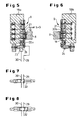
- Fig. 3
- als Einzelheit der Fig. 1 die dort auf dem Oberjoch angeordnete, der Anstellspindel zugeordnete Spann-Kolbenzylindereinheit in einer ersten Betriebsposition;
- Fig. 4
- eine der Fig. 3 entsprechende Darstellung der Spann-Kolbenzylindereinheit in einer weiteren Betriebsposition;
- Fig. 5
- als Einzelheit der Fig. 2 einen Schnitt durch die Führungsbahn entlang der Schnittlinie V-V;
- Fig. 6
- als Einzelheit der Fig. 2 einen Schnitt durch die Führungsbahn entlang der Schnittlinie VI-VI;
- Fig. 7
- ein der Führungsbahn nach Fig. 5 zugeordnetes Mehrwegeventil in einer ersten Betriebsstellung; und
- Fig. 8
- das Mehrwege-Ventil nach Fig. 7 in einer zweiten Betriebsstellung.
- Fig. 1
- a cross roll straightening machine in cross section;
- Fig. 2
- the oblique roller straightening machine of Figure 1 seen along the section line II-II, shown in simplified form with the omission of the top roller arrangement.
- Fig. 3
- as a detail of FIG. 1, the clamping piston cylinder unit arranged there on the upper yoke and assigned to the adjusting spindle in a first operating position;
- Fig. 4
- a representation corresponding to Figure 3 of the clamping piston-cylinder unit in a further operating position.
- Fig. 5
- as a detail of Figure 2 shows a section through the guide path along the section line VV.
- Fig. 6
- as a detail of Figure 2 shows a section through the guideway along the section line VI-VI.
- Fig. 7
- a multi-way valve assigned to the guideway according to FIG. 5 in a first operating position; and
- Fig. 8
- the multi-way valve of FIG. 7 in a second operating position.
Eine in Fig. 1 gezeigte Schrägwalzen-Richtmaschine 1 besitzt einen aus vier Führungssaulen
2 bestehenden, ein Unterjoch 3 und ein Oberjoch 4 miteinander verbindenden
Rahmen. Auf dem Unterjoch 3 ist eine Unterwalze 5 gelagert, während
eine Oberwalze 6 in einem Träger 7 gelagert ist, der von einem Einbaustück 8
aufgenommen wird, das in an den Säulen 2 ausgebildeten Führungsbahnen 9
geführt ist (vgl. auch Fig. 2). Das Einbaustück 8 weist einen in das Oberjoch 8 eingreifenden
Hohlzapfen 10 auf. Dieser ist mit einer Gewindemutter 11 verbunden,
die zur senkrechten Verstellung des Einbaustückes 8 und damit Einstellung des
Richtspaltes zwischen der Ober- und Unterwalze 5, 6 mit einer Anstell- bzw. Gewindespindel
12 zusammenwirkt. Diese wird von einer auf einer mit dem Oberjoch
4 verankerten Konsole 13 angeordneten Verstelleinrichtung 14, z.B. Schneckenrad
und Schnecke, motorbetrieben in Rotation gesetzt. In der Konsole 13 ist weiterhin
eine der Gewindespindel 12 zugeordnete Spann-Kolbenzylindereinheit 15
vorgesehen. Zum Spielausgleich zwischen Gewindemutter 11 und Gewindespindel
12 wird das Einbaustück 8 über Zuggestänge 16 von Zylindereinheiten 17 am
Oberjoch 4 gegen die Spindel verspannt.A cross-roll straightening machine 1 shown in FIG. 1 has one of four
Das Einbaustück 8 ist - wie in Fig. 2 gezeigt - in seinen den Führungsbahnen 9 der
Rahmensäulen 2 zugewandten Bereichen V-förmig ausgeschnitten und in diesen
Bereichen mit korrespondierenden Führungsleisten 18 versehen. Die Führungsbahnen
9 sind in an den Rahmensäulen 2 befestigten Montageblöcken 19a bis d
(vgl. Fig. 2) ausgebildet. Sie bestehen - wie näher den Fig. 5 und 6 zu entnehmen
ist - aus im Ausführungsbeispiel jeweils einem Stellkeil 20a bzw. 20b und einer
komplementären, die Gleitfläche für die Laufleisten 18 des Einbaustückes 8 bereitstellenden,
mit den Montageblöcken 19a bis d verschraubten Gegenplatte 21.
In Durchlaufrichtung 22 (vgl. Fig. 2) des nicht dargestellten Richtguts gesehen ist
von den an den vorderen und hinteren Rahmensäulen 2 angeordneten Stellkeilen
jeweils der eine Stellkeil 20a an eine doppelt wirkende Kolbenzylindereinheit 23
(vgl. Fig. 5) angeschlossen, während dem jeweils anderen Stellkeil 20b eine Anstellschraube
24 (vgl. Fig. 6) zugeordnet ist. Während die Stellkeile 20b über die
Anstellschrauben 24 fest eingestellt sind, lassen sich die hydraulisch beaufschlagten
Stellkeile 20a gesteuert verstellen. Die Anordnung der hydraulisch beaufschlagten
Stellkeile 20a ist dabei gemäß Fig. 2 so, daß die jeweils einander
diagonal gegenüberliegenden Führungsbahnen mit solch einem hydraulisch beaufschlagten
Stellkeil 20a ausgestattet sind.The
Durch Ansteuerung einerseits der Spann-Kolbenzylindereinheit 15 und andererseits
der Kolben-Zylinder-Einheiten 23 der Stellkeile 20a läßt sich damit eine Einstellung
der Schrägwalzen-Richtmaschine 1 einerseits für den Blankbetrieb und
andererseits den Schwarzbetrieb vornehmen. Zur gewünschten Beaufschlagung
des Zylinderkolbens 25 der Spann-Kolbenzylindereinheit 15 sowie des Zylinderkolbens
26 der Kolben-Zylinder-Einheiten 23 sind an die Spann-Kolbenzylindereinheit
15 und die Kolben-Zylinder-Einheiten 23 Druckmittelleitungen
27, 28 bzw. 29, 30 angeschlossen (vgl. Fig. 3 bzw. die Fig. 5 sowie 7 und 8),
die mit einer nicht dargestellten Druckmittelquelle und einer Steuereinheit verbunden
sind. Weiterhin weisen die Leitungen 27, 28 bzw. 29, 30 ein integriertes
Mehrwegeventil 31 bzw. 32 auf, und an die Spann-Kolbenzylindereinheit 15 ist in
der Druckseite noch ein einstellbares Druckbegrenzungsventil 33 vorgesehen.By controlling the tensioning piston-
Zum Richten von Blankmaterial wird die mittels der Anstell- bzw. Gewindespindel
12 zwischen den Walzen 5, 6 eingestellte Richtspalthöhe durch Vorspannung der
Schrägwalzen-Richtmaschine 1 ohne Ausweichmöglichkeit eingehalten, indem der
Zylinderkolben 25 der Spann-Kolbenzylindereinheit 15 mit Pmax beaufschlagt und
ohne einen Spalt bzw. mit Spalt S = 0 mm (vgl. Fig. 3) auf Block gefahren wird.
Zusätzlich werden über die Kolben-Zylinder-Einheiten 23 die Stellkeile 20a so weit
verschoben, bis auch das Führungsspiel des Einbaustücks 8 in den Führungsbahnen
9 auf Null reduziert wird, was mit der in Fig. 7 gezeigten Stellung des Mehrwegeventils
32 der Fall ist. Das Blankmaterial durchläuft somit bei fest eingestelltem
Richtspalt die Walzen 5, 6.The straightening of blank material is carried out by means of the adjusting or threaded
Beim Richten von Schwarzmaterial wird hingegen die Richtspalthöhe zwischen
den Walzen 5, 6 um einen Betrag X kleiner eingestellt als der aktuelle Richtgutdurchmesser.
Durch Umsteuern des Mehrwegeventils 31 - die Umsteuerposition
ist in Fig. 4 nicht gezeigt - wird der Zylinderkolben 25 in der Spann-Kolbenzylindereinheit
15 in die in Fig. 4 dargestellte Zwischenposition gestellt, in
der er im Vergleich zur Blocklage nach Fig. 3 einen dem Maß X der reduzierten
Richtspalthohe entsprechenden Spalt S1 zur Blocklage definiert. Im Rahmen der
Größe von S1 bzw. dem Betrag X kann der Zylinderkolben 25 schwimmen, um die
Formabweichung des Richtgutdurchmessers auszugleichen. Dies wird dadurch
ermöglicht, daß gleichzeitig das Mehrwegeventil 32 der Kolben-Zylinder-Einheiten
23 der Stellkeile 20a in die Position nach Fig. 8 verstellt wurde, in der die dazugehörigen
Führungsbahnen 9 keiner Klemmwirkung unterliegen. Das Einbaustück 8
wird lediglich mit dem über die Anschlagschrauben 24 an den Stellkeilen 20b der
beiden anderen Führungsbahnen 9 gering eingestelltem Spiel geführt.When straightening black material, however, the straightening gap height between
the
Claims (6)
- Straightening machine with skew rolls, consisting of a frame which is formed by a lower yoke (3), an upper yoke (4) and columns connecting these and which receives rolls rotatably mounted in roll seats, wherein the roll seat of the lower roll (5) is arranged in the lower yoke and the roll seat of the upper roll (6), which is acted on by an adjusting spindle, is arranged in the upper yoke to be vertically adjustable and the rolls are mounted to be pivotable about a vertical centre axis for setting the angle of intersection of the roll axes, characterised in that the upper roll (6) is arranged in a chock (8), which is guided by four guide surfaces (18) between guide tracks (9), which have integrated setting wedges (20a; 20b) or adapter strips, at the columns (2) of the frame, of which at the front or back frame columns as seen in the transit direction (22) of the material to be straightened each time one setting wedge (20a) of the guide tracks (9) is hydraulically adjustable by a double-acting piston-cylinder unit (23) and the other setting wedge (20b) is mechanically 15 adjustable, and in addition the chock (8) is constructed with a hollow pin (10) for guidance in the upper yoke (4), which is provided with a threaded nut (11) for vertical adjustment of the chock (8) by means of a threaded spindle (12), wherein a double-acting tightening piston-cylinder unit (15) is associated with the threaded spindle (12) at the upper yoke (4).
- Straightening machine with skew rolls according to claim 1, characterised in that a tie rod (16) arranged at the upper yoke (4) and acted on by a piston-cylinder unit (17) is connected with the chock (8).
- Straightening machine with skew rolls according to claim 1 or 2, characterised in 25 that the tightening piston-cylinder unit (15) of the threaded spindle (12) and the piston-cylinder units (23) of the hydraulically moved setting wedges (20a) are loaded at the same time with maximum pressure.
- Straightening machine with skew rolls according to claim 1 or 2, characterised in that the tightening piston-cylinder unit (15) of the threaded spindle (12) is loaded with maximum pressure and the piston-cylinders units (23) of the hydraulically moved setting wedges (20a) are free of pressure.
- Straightening machine with skew rolls according to claim 1 or 2, characterised in 35 that in the case of a straightening gap height, which is set to be smaller than the actual diameter of the material to be straightened, of the rolls (5, 6) the tightening piston-cylinder unit (15) is loaded for floating support of the threaded spindle (12) and the piston-cylinder units (23) of the hydraulically moved setting wedges (20a) are free of pressure.
- Straightening machine with skew rolls according to claim 5, characterised by a settable pressure limiting valve (33) arranged in the pressure side of the pressure medium supply of the tightening piston-cylinder unit (16).
Applications Claiming Priority (2)
| Application Number | Priority Date | Filing Date | Title |
|---|---|---|---|
| DE10000349 | 2000-01-07 | ||
| DE10000349A DE10000349C2 (en) | 2000-01-07 | 2000-01-07 | Piercer roll straightener |
Publications (3)
| Publication Number | Publication Date |
|---|---|
| EP1114682A2 EP1114682A2 (en) | 2001-07-11 |
| EP1114682A3 EP1114682A3 (en) | 2002-10-16 |
| EP1114682B1 true EP1114682B1 (en) | 2004-07-28 |
Family
ID=7626875
Family Applications (1)
| Application Number | Title | Priority Date | Filing Date |
|---|---|---|---|
| EP00125182A Expired - Lifetime EP1114682B1 (en) | 2000-01-07 | 2000-11-18 | Straightening machine with obliquely mounted rolls |
Country Status (5)
| Country | Link |
|---|---|
| US (1) | US6412323B2 (en) |
| EP (1) | EP1114682B1 (en) |
| JP (1) | JP3453364B2 (en) |
| DE (2) | DE10000349C2 (en) |
| ES (1) | ES2223374T3 (en) |
Cited By (1)
| Publication number | Priority date | Publication date | Assignee | Title |
|---|---|---|---|---|
| DE102020201477A1 (en) | 2020-02-06 | 2021-08-12 | Sms Group Gmbh | Device and method for adjusting or adjusting a roll gap of a two-roll straightening machine for bars and / or profiles |
Families Citing this family (11)
| Publication number | Priority date | Publication date | Assignee | Title |
|---|---|---|---|---|
| CN100371469C (en) * | 2005-12-16 | 2008-02-27 | 俞学文 | Continuous heat treatment machine for fine long fastener and continuous heat treatment method |
| CN101569901B (en) * | 2009-06-15 | 2011-01-05 | 合肥海德数控液压设备有限公司 | Lifting hydrostatic press |
| CN101912878B (en) * | 2010-08-05 | 2012-04-18 | 太原通泽重工有限公司 | Open-rack three-roller oblique rolling extender |
| CN102172713B (en) * | 2010-12-30 | 2012-10-24 | 一重集团大连设计研究院有限公司 | Omnidirectional swing stopping device for pressure head |
| CN103042076B (en) * | 2012-12-28 | 2014-11-26 | 太原通泽重工有限公司 | Rotating hub type under-pressure balancing device of straightener |
| CN103722017B (en) * | 2013-12-30 | 2015-06-24 | 中冶京诚工程技术有限公司 | Rotating angle adjusting device of rod loosening machine |
| CN103769442B (en) * | 2014-01-24 | 2015-08-05 | 太原科技大学 | Bar two-roll reeler guide roller device |
| CN106783302B (en) * | 2016-12-28 | 2018-11-27 | 歌尔科技有限公司 | A kind of buckle-type key correction tooling and antidote |
| MX2021012953A (en) | 2019-04-23 | 2021-11-25 | Jfe Steel Corp | Rolling-straightening machine and method for manufacturing pipe or bar using rolling-straightening machine. |
| CN112474889B (en) * | 2020-12-21 | 2022-11-29 | 东台市高科技术创业园有限公司 | Nonrust steel pipe straightener of longitudinal adjustment formula |
| CN117380770B (en) * | 2023-12-06 | 2024-02-20 | 潍坊天信散热器有限公司 | Inclined roller straightener for heat dissipation aluminum pipe |
Family Cites Families (6)
| Publication number | Priority date | Publication date | Assignee | Title |
|---|---|---|---|---|
| DE1910879C3 (en) * | 1969-03-04 | 1978-12-07 | Th. Kieserling & Albrecht, 5650 Solingen | Straightening machine for elongated workpieces with a round cross-section |
| JPS5744624U (en) * | 1980-08-21 | 1982-03-11 | ||
| DE3132712C2 (en) * | 1981-08-19 | 1985-09-12 | Kocks Technik Gmbh & Co, 4010 Hilden | Tube piercing mill |
| US4471639A (en) * | 1982-11-01 | 1984-09-18 | E. W. Bliss Company, Inc. | Roll orientation control system for straightening machines |
| SU1507493A1 (en) * | 1986-10-08 | 1989-09-15 | Старо-Краматорский машиностроительный завод им.Орджоникидзе | Mechanism of radial setting-up of skew-roll straightener |
| US4989432A (en) * | 1990-01-16 | 1991-02-05 | Turner Machine Company | System and method of detecting roll position in a rotary straightener |
-
2000
- 2000-01-07 DE DE10000349A patent/DE10000349C2/en not_active Expired - Lifetime
- 2000-11-18 DE DE50007196T patent/DE50007196D1/en not_active Expired - Lifetime
- 2000-11-18 ES ES00125182T patent/ES2223374T3/en not_active Expired - Lifetime
- 2000-11-18 EP EP00125182A patent/EP1114682B1/en not_active Expired - Lifetime
-
2001
- 2001-01-04 JP JP2001000257A patent/JP3453364B2/en not_active Expired - Lifetime
- 2001-01-05 US US09/755,604 patent/US6412323B2/en not_active Expired - Lifetime
Cited By (2)
| Publication number | Priority date | Publication date | Assignee | Title |
|---|---|---|---|---|
| DE102020201477A1 (en) | 2020-02-06 | 2021-08-12 | Sms Group Gmbh | Device and method for adjusting or adjusting a roll gap of a two-roll straightening machine for bars and / or profiles |
| WO2021156205A1 (en) | 2020-02-06 | 2021-08-12 | Sms Group Gmbh | Device and method for adjusting or setting a rolling gap of a two-roll straightening machine for rods and/or profiles |
Also Published As
| Publication number | Publication date |
|---|---|
| DE10000349C2 (en) | 2002-04-04 |
| JP3453364B2 (en) | 2003-10-06 |
| JP2001219218A (en) | 2001-08-14 |
| DE50007196D1 (en) | 2004-09-02 |
| ES2223374T3 (en) | 2005-03-01 |
| EP1114682A3 (en) | 2002-10-16 |
| US6412323B2 (en) | 2002-07-02 |
| US20010023604A1 (en) | 2001-09-27 |
| EP1114682A2 (en) | 2001-07-11 |
| DE10000349A1 (en) | 2001-08-02 |
Similar Documents
| Publication | Publication Date | Title |
|---|---|---|
| EP0551584B1 (en) | Mould clamping device for injection moulding machines | |
| EP1114682B1 (en) | Straightening machine with obliquely mounted rolls | |
| EP0005760B1 (en) | Straightening machine for sheets and strips | |
| EP0556631B1 (en) | Universal rolling stand | |
| DE593557C (en) | Rolling mill with overhung work rolls | |
| EP0722820A1 (en) | Tie bar-less mould clamping device | |
| DE2552034A1 (en) | CALENDERS WITH GAP LIMITING PLATES | |
| DE1602176A1 (en) | Rolling frame, in particular for rolling out sheet metal or strips, consisting of a rough adjustment and a fine adjustment of the rollers under rolling pressure | |
| DE2341768A1 (en) | Cold-rolling cluster mill - with backing-up rolls axially displaceable in opposite directions to suit strip width | |
| DE2747331C2 (en) | Device for adjusting support rollers | |
| EP1324868B1 (en) | Mold closing device for injection molding machines | |
| EP0602492A1 (en) | Cluster mill | |
| EP0838277B1 (en) | Leveller for levelling strips to be fed to the entrance of a press | |
| DE1809260A1 (en) | Rolling mill | |
| DE3317635A1 (en) | Hot-rolling method | |
| EP1943032B1 (en) | Apparatus for adjusting working rolls to the rolling line | |
| DE69912076T2 (en) | Piercing mill | |
| EP0022136B1 (en) | Straightening machine with obliquely mounted rolls | |
| DE1961110A1 (en) | Pre-stressed rolling mill allows rapid - roll changing | |
| EP2310150A2 (en) | Roller arrangement | |
| DE2743560A1 (en) | Screw spindles operated by worm gear drive - connect adjustable rolling cylinder mounting bridges | |
| DE2241834B2 (en) | Device for setting a vertical roller chock | |
| EP3536413B1 (en) | Rolling stand for a hot rolling mill | |
| DE540062C (en) | Machine for straightening sheet metal and metal strips | |
| DE1221856B (en) | Device for adjustable relief of the slide ways of a slide on a machine tool |
Legal Events
| Date | Code | Title | Description |
|---|---|---|---|
| PUAI | Public reference made under article 153(3) epc to a published international application that has entered the european phase |
Free format text: ORIGINAL CODE: 0009012 |
|
| AK | Designated contracting states |
Kind code of ref document: A2 Designated state(s): AT BE CH CY DE DK ES FI FR GB GR IE IT LI LU MC NL PT SE TR |
|
| AX | Request for extension of the european patent |
Free format text: AL;LT;LV;MK;RO;SI |
|
| PUAL | Search report despatched |
Free format text: ORIGINAL CODE: 0009013 |
|
| AK | Designated contracting states |
Kind code of ref document: A3 Designated state(s): AT BE CH CY DE DK ES FI FR GB GR IE IT LI LU MC NL PT SE TR |
|
| AX | Request for extension of the european patent |
Free format text: AL;LT;LV;MK;RO;SI |
|
| 17P | Request for examination filed |
Effective date: 20030411 |
|
| AKX | Designation fees paid |
Designated state(s): DE ES GB IT |
|
| GRAP | Despatch of communication of intention to grant a patent |
Free format text: ORIGINAL CODE: EPIDOSNIGR1 |
|
| GRAS | Grant fee paid |
Free format text: ORIGINAL CODE: EPIDOSNIGR3 |
|
| GRAA | (expected) grant |
Free format text: ORIGINAL CODE: 0009210 |
|
| AK | Designated contracting states |
Kind code of ref document: B1 Designated state(s): DE ES GB IT |
|
| REG | Reference to a national code |
Ref country code: GB Ref legal event code: FG4D Free format text: NOT ENGLISH |
|
| REG | Reference to a national code |
Ref country code: IE Ref legal event code: FG4D Free format text: GERMAN |
|
| REF | Corresponds to: |
Ref document number: 50007196 Country of ref document: DE Date of ref document: 20040902 Kind code of ref document: P |
|
| GBT | Gb: translation of ep patent filed (gb section 77(6)(a)/1977) |
Effective date: 20041209 |
|
| REG | Reference to a national code |
Ref country code: ES Ref legal event code: FG2A Ref document number: 2223374 Country of ref document: ES Kind code of ref document: T3 |
|
| REG | Reference to a national code |
Ref country code: IE Ref legal event code: FD4D |
|
| PLBE | No opposition filed within time limit |
Free format text: ORIGINAL CODE: 0009261 |
|
| STAA | Information on the status of an ep patent application or granted ep patent |
Free format text: STATUS: NO OPPOSITION FILED WITHIN TIME LIMIT |
|
| 26N | No opposition filed |
Effective date: 20050429 |
|
| REG | Reference to a national code |
Ref country code: GB Ref legal event code: 732E |
|
| REG | Reference to a national code |
Ref country code: GB Ref legal event code: 732E Free format text: REGISTERED BETWEEN 20090319 AND 20090325 |
|
| PG25 | Lapsed in a contracting state [announced via postgrant information from national office to epo] |
Ref country code: IT Free format text: LAPSE BECAUSE OF NON-PAYMENT OF DUE FEES Effective date: 20081118 |
|
| PGRI | Patent reinstated in contracting state [announced from national office to epo] |
Ref country code: IT Effective date: 20110616 |
|
| PGFP | Annual fee paid to national office [announced via postgrant information from national office to epo] |
Ref country code: IT Payment date: 20191009 Year of fee payment: 20 Ref country code: ES Payment date: 20191204 Year of fee payment: 20 |
|
| PGFP | Annual fee paid to national office [announced via postgrant information from national office to epo] |
Ref country code: GB Payment date: 20191009 Year of fee payment: 20 Ref country code: DE Payment date: 20200110 Year of fee payment: 20 |
|
| REG | Reference to a national code |
Ref country code: GB Ref legal event code: PE20 Expiry date: 20201117 |
|
| PG25 | Lapsed in a contracting state [announced via postgrant information from national office to epo] |
Ref country code: GB Free format text: LAPSE BECAUSE OF EXPIRATION OF PROTECTION Effective date: 20201117 |
|
| REG | Reference to a national code |
Ref country code: ES Ref legal event code: FD2A Effective date: 20211230 |
|
| PG25 | Lapsed in a contracting state [announced via postgrant information from national office to epo] |
Ref country code: ES Free format text: LAPSE BECAUSE OF EXPIRATION OF PROTECTION Effective date: 20201119 |