EP1111816A1 - Verfahren und Anordnung zum Verbindungsaufbau zwischen Satelliten - Google Patents
Verfahren und Anordnung zum Verbindungsaufbau zwischen Satelliten Download PDFInfo
- Publication number
- EP1111816A1 EP1111816A1 EP00121733A EP00121733A EP1111816A1 EP 1111816 A1 EP1111816 A1 EP 1111816A1 EP 00121733 A EP00121733 A EP 00121733A EP 00121733 A EP00121733 A EP 00121733A EP 1111816 A1 EP1111816 A1 EP 1111816A1
- Authority
- EP
- European Patent Office
- Prior art keywords
- light
- optical fiber
- acquisition
- signal
- fiber
- Prior art date
- Legal status (The legal status is an assumption and is not a legal conclusion. Google has not performed a legal analysis and makes no representation as to the accuracy of the status listed.)
- Granted
Links
- 238000000034 method Methods 0.000 title claims abstract description 12
- 230000003287 optical effect Effects 0.000 claims description 28
- 239000013307 optical fiber Substances 0.000 claims description 19
- 230000007246 mechanism Effects 0.000 claims description 8
- 230000001427 coherent effect Effects 0.000 claims description 4
- 239000000835 fiber Substances 0.000 description 53
- 238000004891 communication Methods 0.000 description 19
- 230000005540 biological transmission Effects 0.000 description 7
- 230000005855 radiation Effects 0.000 description 6
- 230000010287 polarization Effects 0.000 description 5
- 239000007787 solid Substances 0.000 description 4
- 238000001514 detection method Methods 0.000 description 3
- 230000000694 effects Effects 0.000 description 3
- 230000001629 suppression Effects 0.000 description 3
- 238000005452 bending Methods 0.000 description 2
- 238000010586 diagram Methods 0.000 description 2
- 238000009826 distribution Methods 0.000 description 2
- 239000003365 glass fiber Substances 0.000 description 2
- 230000007774 longterm Effects 0.000 description 2
- 230000035772 mutation Effects 0.000 description 2
- 238000005457 optimization Methods 0.000 description 2
- 230000002457 bidirectional effect Effects 0.000 description 1
- 230000033228 biological regulation Effects 0.000 description 1
- 230000008859 change Effects 0.000 description 1
- 238000010276 construction Methods 0.000 description 1
- 239000013078 crystal Substances 0.000 description 1
- 230000001419 dependent effect Effects 0.000 description 1
- 238000006073 displacement reaction Methods 0.000 description 1
- 230000005684 electric field Effects 0.000 description 1
- 238000001914 filtration Methods 0.000 description 1
- 230000004907 flux Effects 0.000 description 1
- 230000020169 heat generation Effects 0.000 description 1
- 238000005286 illumination Methods 0.000 description 1
- 230000002452 interceptive effect Effects 0.000 description 1
- 238000004519 manufacturing process Methods 0.000 description 1
- 239000011159 matrix material Substances 0.000 description 1
- 239000003471 mutagenic agent Substances 0.000 description 1
- 230000005693 optoelectronics Effects 0.000 description 1
- 230000001681 protective effect Effects 0.000 description 1
- 230000009467 reduction Effects 0.000 description 1
- 238000010845 search algorithm Methods 0.000 description 1
- 239000004065 semiconductor Substances 0.000 description 1
- 238000000926 separation method Methods 0.000 description 1
- 230000006641 stabilisation Effects 0.000 description 1
- 238000011105 stabilization Methods 0.000 description 1
- 238000003860 storage Methods 0.000 description 1
- 230000001360 synchronised effect Effects 0.000 description 1
- 230000009897 systematic effect Effects 0.000 description 1
- 238000011144 upstream manufacturing Methods 0.000 description 1
Images

Classifications
-
- H—ELECTRICITY
- H04—ELECTRIC COMMUNICATION TECHNIQUE
- H04B—TRANSMISSION
- H04B10/00—Transmission systems employing electromagnetic waves other than radio-waves, e.g. infrared, visible or ultraviolet light, or employing corpuscular radiation, e.g. quantum communication
- H04B10/11—Arrangements specific to free-space transmission, i.e. transmission through air or vacuum
- H04B10/118—Arrangements specific to free-space transmission, i.e. transmission through air or vacuum specially adapted for satellite communication
Definitions
- the present invention relates to a method for establishing a connection between a Receiver and a transmitter located away from it by means of data signals and Light waves carrying beacon light, being used to acquire the light waves in the receiver Acquisition sensor is present, the acquisition sensor signals from the received light waves generated.
- a "wide-angle camera” is sometimes used in cooperation between two satellites used with a so-called beacon laser.
- the camera is usually designed so that it can survey the entire uncertainty cone resulting from the positional uncertainty of the own and the opposite station as well as the uncertainty of both stations regarding tilting arises in the inertial system.
- the camera must be one Survey angular range of against ⁇ 0.5 °.
- the natural Beam divergence of the communication beam used only a few micro-radians. This fact requires an extremely large dynamic range of the ratio Viewing angle / achievable angular resolution.
- Alignment errors also make matters worse between the optics of the wide-angle camera and the search optics of the communication beam out. Due to certain natural mechanical causes, the broadcast beam will change move in a random manner in a certain solid angle range. Conditionally due to the limited achievable resolution of the wide-angle camera as well as its limited electrical bandwidth there is therefore a very high probability that the Communication beam only very rarely illuminates the opposite station. The opposite station is therefore not able to align itself with the received communication beam and thus initiate the higher-frequency "tracking" with high angular resolution. in the Communication mode is usually followed by the tracking of the opposite station Help of the received communication light. To obtain the spatial filing signals (Tracking signals) become sensors with high spatial and / or electrical resolution used.
- a device with a local laser and with two detectors is also known from EP-0 831 604-A1 , each comprising two identical detector halves, each with a strip-shaped interruption or gaps in the Photodiode electrode area are separated between the adjacent halves, the gaps of the two detectors being arranged orthogonally to one another.
- This device is used as a directionally selective single mode optical receiver. In this case, shading is present both in a receiving telescope of this device and in the beam path of the local laser. This makes it possible to generate an error signal for spatial beam control of an optical heterodyne receiver, largely avoiding the systematic losses and at the same time minimally impairing the data signal to be transmitted with a good signal-to-noise ratio.
- an optical bench is known from EP-0 844 473-A1, the bench structure of which is designed such that when the arms are heat-dilated, which are provided for connecting receiving parts for different optical units, the receiving parts can be displaced transversely to axes without tilting that occupy certain angular positions among themselves and relative to the bank structure.
- Such an optical bench can be combined with the device mentioned at the beginning.
- Such “tracking sensor” methods allow simultaneous communication and Determine the spatial tracking error that the corresponding devices prove however, is disadvantageous with regard to the relatively high adjustment effort, in particular their manufacture.
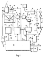
- an Rx wave or information light wave 1 carrying a data signal is received according to FIG. 1 via a receiving unit consisting of a receiving telescope 2, a fine alignment mechanism 3 and a lens 4 .
- Wave 1 also contains beacon light, which does not arrive sharply focused but arrives at a relatively wide angle.
- the received light wave 1 is fed to an optical fiber coupler 6 via a fiber nutator 5 .
- One end of a polarization-maintaining monomode fiber 7 can be connected to the fiber nutator 5 in order to receive the radiation received via the optical receiving unit as far as the fiber optic coupler 6 and further monomode fibers 8 and 9 up to a detector 10 and 11, respectively.
- the radiation received via the optical receiving unit is preferably guided via a chromatic diplexer 51 and a single-mode fiber 52 for data light to the fiber optic coupler 6 .
- Such a fiber nutator 5 is essentially a deflection unit with a fiber, which is driven for nutation, for example, by a piezomechanism.
- a local laser 12 further preferably polarisationser-retaining monomode fiber 13 is connected to the generated from the local laser 12 radiation to the fiber optic coupler 6 and then via the single-mode fibers 8 and 9 to the two detectors 10 and 11 to lead.
- the detectors 10 and 11 do not have to be split as in the known device.
- the deflection unit 5 can receive control signals Sp from a control 14 via a bus or lines.
- the fiber optic coupler 6 is preferably a 50 % to 50 % coupler. A simple and at the same time inherently stable construction can be achieved with a polarization maintaining fiber coupler.
- an electro-optical deflector can also be used as the deflection unit, in which an electrical voltage generates a linear electrical field gradient across the aperture of an electro-optical crystal. With such a deflector, an aperture of approximately 1 mm can also be easily reached.
- the detectors 10 and 11 deliver signals Sa and Sb via an amplifier 15 and 16, respectively , which are used as useful signals.
- the low-frequency component of these signals Sa and Sb is also fed to the differential inputs of a differential amplifier 17 .
- the device according to the invention additionally comprises a sensor 53, which is connected to the output of the diplexer 51 via a fiber 54, preferably a single-mode fiber, and two discriminators 56, 57, a higher-level system controller 58 and a CPA unit (Coarse Pointing Assembly ) 174.
- the sensor or detector 53 which is faster than the acquisition sensor 171 , can be a photodiode, for example.
- the discriminators 56 and 57 which can be synchronous demodulators and amplifiers, are connected on the input side to an output of the sensor 53 and the amplifier 17 , respectively.
- a reflection surface R4 acting as a beam splitter in order to deflect the radiation which then arrives at an acquisition sensor ( AS ) 171 via a preferably permanently mounted focusing device FA , as it is anyway, but in a different form in devices of the latter Type exists.
- Sensor 171 is a large-area matrix sensor with an area of, for example, 6 ⁇ 8 mm 2 , which is scanned and is therefore slow.
- the system control 58 has input signals Sc, Sm and Sn from the sensor 171 and the discriminators 56, 57 applied to it on the input side.
- the system controller 58 has various outputs in order to deliver signals to a CPA unit 174, an FPA control electronics 175 or a PAA unit via lines 191, 192, 193 , and is also bidirectional with the control unit 14, which also Deflector modulation is connected.
- the receiving telescope 2 is activated by an output signal Sg from the CPA unit 174, the fine alignment mechanism 3 by a control signal Sf from the unit 175 and the lens 4, the deflection unit 5 and the discriminators 56, 57 by signals So, Sp and St ( FIG. 1 ) controlled.
- the signals Sp and St are quadrature signals (sin ⁇ t, cos ⁇ t), as are used, for example, to generate Lissajous figures.
- the light spot 22 guided by this controlled movement 21 projects onto a diametrical surface at the end of the optical fiber of the deflection unit 5 .
- the light spot 22 can be brought at least approximately to the center of the optical fiber.
- the system controller 58 is to move the fine alignment mechanism 3, the end of the fiber 7 and / or the lens 4, in such a way that this modulation signal 32 reaches a minimum value or the value zero.
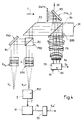
- a terminal can be provided for three channels, namely for a transmit channel Tx, for a receive channel Rx1 with a fiber nutator 5 (FIGS . 1 and 4 ), which is considered as receive sensor RS1 , and for an acquisition channel Ax an acquisition sensor ( AS ) 171 ( FIGS. 4 and 1 ).
- a collimator device KTX a first reflection surface R1, a second reflection surface R2, a third reflection surface R3, a fourth reflection surface R4, a fifth reflection surface R5 and a quarter wave plate QWP1 are arranged in the transmission channel Tx .
- the first reflection surface R1 is part of a point-ahead assembly ( PAA ) .
- the second reflection surface R2 is part of a polarizing beam splitter ( PBS ) , which is designed such that it is reflective for rays with the polarization of the transmitted beam and transmissive for rays with the polarization of the received beam as lossless as possible.
- the fourth reflection surface R4 is formed, for example, by a dichroic beam splitter (dichroic beam splitter) DBS .
- the fifth reflection surface R5 is formed by a fine pointing device ( FPA ) ( FIGS. 4 and 1 ) .
- the quarter-wave plate QWP1 converts the previously linearly polarized light of the transmission channel into circularly polarized light for transmission in space to the partner terminal .
- the receiving channel Rx1 also seen in the beam direction, comprises the quarter-wave plate QWP1, the fifth reflection surface R5 , the dichroic splitter DBS, the third reflection surface R3, the reflecting beam splitter PBS, a focusing device FR1 and the fiber nutator 5 and the reception sensor RS1.
- the quarter-wave plate QWP1 converts the circularly polarized light from the partner terminal arriving through space into linearly polarized light.
- the purpose of the PBS beam splitter is to differentiate between the transmit and receive beams. It is required in the present exemplary embodiment or in cases in which the transmit and receive beams differ by different polarization. In other exemplary embodiments, in which the transmit and receive beam differ, for example, by different wavelengths, a DBS would be used instead of the PBS .
- the send channel is used to transmit data to the partner terminal, and the receive channel is used to receive data from the partner terminal, each in an operating mode in which both terminals are already roughly aligned with one another.
- the rough alignment device 174 ( FIG. 1, CPA, Coarse Pointing Assembly) is used for the rough alignment; On the one hand, this comprises a light beacon arranged at the partner terminal for emitting a beacon light and, on the other hand, the acquisition channel at the terminal for receiving the beacon light.
- the acquisition channel separates from the reception channel Rx in the dichroic divider DBS and has a focusing device FA ( FIG. 4 ) and the acquisition sensor AS .
- the detection area AA of the acquisition sensor AS is significantly larger than the detection area RA of the reception sensor.
- the light wave 1 comprises the data transmission communication beam, also called data light, and beacon light.
- the data light is heavily bundled and, due to the "wobble" that arises in the acquisition phase, it is very likely that it will not hit the opposite station.
- the beacon beam is less concentrated, which enables permanent illumination of the opposite station. So you first have the option to track the received beacon light with the acquisition sensor 171 . At the same time, you can try to switch to the nutator 5 with the leak light. Since this is all done with the remote station permanently illuminated, there is no "twinkling” effect as if you were using the communication beam. So if you don't hit the fiber nutator immediately, you have time to look for the light spot.
- the light wave received by the optical receiving unit 2, 3 ( FIG. 1) or by the elements FPA, R4, R3, PBS and FR1 ( FIG. 4 ) is transmitted via the fine alignment unit 3 and with the aid of the lens 4 or the elements PBS , FR1 ( Fig. 4 ) focused approximately on the center of the single-mode fiber 7 (Fig. 1 ) in the fiber nutator 5 (Fig. 1, 4 ) when the control unit is at rest.
- the control unit 14 (FIG. 1) is active, the fiber nutator 5 causes the fiber end 22 to move (FIG. 2 ) around the center of the single-mode fiber 7 .
- the fiber end 22 preferably describes a high-frequency circular movement about the optical axis of the receiving optics.
- the high-frequency mechanical scanning movement of the fiber end caused by the nutator 5 (FIGS . 1, 4 ), which can generally be a deflection unit, can be controlled, for example, by means of a lateral displacement mechanism or by means of a bending element.
- Fast lateral slide units with small movements are known, for example, from optoelectronic readers such as CD players.
- Bending elements on the other hand, can be easily made from piezoceramic tubes with segmented electrodes. These tubes are only firmly fixed in one area so that they can bend in the longitudinal direction due to the piezo effect. All mechanisms have in common that they are controlled by so-called IQ signals. After 1-Q demodulation of the intensity signal, the spatial error between the light spot 22 and the fiber axis is finally obtained.
- the error signals Sm and Sn ( FIG. 1 ) have the effect via system control 58 that the storage error is minimized.
- the relative offset generated by the rotational movement between the intensity distribution of the Rx light in the focal plane of the lens 4 and the end of the fiber 7 thus results in a time-asymmetrical intensity signal on the detectors 10 and 11 if the fiber axis is not concentric about the optical axis of the optomechanical Systems scans.
- the scanning point detector is thus replaced, with very good approximation, by the mode field of a single-mode fiber.
- the scan radius should not exceed 1/10 of the mode field radius.
- the light wave guided through the chromatic diplexer 51 is divided by the beam splitter 6 into two almost identical partial beams, which are each fed to one of the detectors 10 and 11 after the light from the local laser 12 has been coupled into the luminous flux via the fiber optic coupler 6 .
- Two error component signals are generated by the two detectors 10, 11, which are each converted into voltages Sa and Sb via a corresponding front-end transimpedance amplifier 15 and 16, respectively.
- a spatial error signal is obtained from the signals Sa and Sb by forming the difference, which appears as signal Sn ( ⁇ x, ⁇ y) at the output of the circuit 57 and is used for continuous tracking operation.
- the correct addition of the error component signals Sa and Sb results in an output signal corresponding to the original data or communication signal.
- the invention therefore replaces a tracking sensor ( TS ) present in such devices in addition to an acquisition sensor AS and a pointing sensor 173 .
- the local laser wave is only superimposed on the Rx wave in the glass fiber, so that the spatial degree of correlation between the local laser and the Rx field will be equal to 1 , which means that streak-free superimposition is guaranteed.
- a guaranteed streak-free overlay and adjust to the absolute amplitude maximum. This proves to be very advantageous compared to the free jet superposition, in which, in contrast to the method according to the invention, it can happen that interference fringes occur due to a tilt angle when the two waves are superimposed.
- the optimal, i.e. streak-free, adjustment state can then no longer be found by the intensity maximum alone.
- the level difference between the main maximum and one of the secondary maxima is then relatively small. There is then always a latent danger that the tracking controller will get out of step and regulate to a secondary maximum of the intensity distribution, which then considerably limits the linear control range.
- the fiber mutators have a selectively small field of view due to their single mode, very high solid angle resolutions can be achieved (submicro-radians).
- the beam of the beacon laser is not bundled as much as the communication beam, permanent lighting is therefore already possible with the wide-angle camera the opposite station.
- the light from the beacon laser (s), which comes from powerful laser diodes, for example, is coupled into multimode fibers.
- the polarization state of the emitted light is therefore random.
- the diplexers R4 used are optimized for low transmission losses for the communication light. Consequently, with respect to the beacon light, "crosstalk" of the beacon wavelength always occurs in the communication channel, which means that the beacon light reaches the direction of the communication receiver on the receiving side. Thanks to the fiber front end, which is used in the communication receivers according to the fiber nutation principle, it is also possible to use the leakage light from the acquisition channel to generate tracking signals.
- the acquisition sensor 171 and the coarse pointing assembly 174 operate in a manner known per se. So first or at the beginning you have the possibility to track the received beacon light with the help of the signal Sc, whereby a control loop via the elements 58, 174, 2, FPA, R4, 171 is used as an alternative for tracking Sensor 171 requires a slow control bandwidth, for example in the order of 50 Hz.
- the signal Sn at the output of the discriminator 57 is basically used by the system controller 58 in continuous tracking operation.
- an inner control loop determined by elements 57, 58, 175, 3, 51 and 6 acts.
- an outer control loop determined by elements 58, 174 and 2 also acts.
- These control loops are very fast because sensors 10, 11 and 53, which are point sensors in combination with a glass fiber, so to speak, can work much faster than sensor 171 .
- the signal Sm at the output of the discriminator 57 is only used temporarily, and only at the beginning, possibly for a maximum time of, for example, three minutes.
- the system controller 58 has means to determine whether the signals Sc, Sm and Sn are useful.
- the reception for the signal Sc is unproblematic.
- This signal Sc is therefore initially used until the system controller 58 determines whether the signal Sm is usable, that is to say whether or not the fiber nutator receives enough light leakage to generate tracking signals. From this moment on, it works with this signal Sm, whereby for safety reasons the sensor 171 can be continued to run in the acquisition phase. If the system controller 58 then determines that the signal Sn is valid or that the communication channel is running correctly, it takes over this signal Sn for a more accurate continuous tracking operation. At this moment, the signal Sm of the discriminator 56 can be switched off by an enable signal S6 and, at the latest now, the signal Sc can also be switched off by an enable signal S1 .
- enable signals S1 and S6 and a further enable signal S7 for the discriminator 57 are generated in the system controller 58 , which also requires the signals Sc, Sm and Sn to control the CPA and the FPA .
- Incoherent system realizations or direct detection systems are sometimes implemented in such a way that incoming light from the opposite station is focused on a so-called avalanche diode.
- Such systems are inherently not single-mode receivers. That means the recipient accepts light from a solid angle range that is larger than that by diffraction theory solid angle range described for diffraction-limited systems.
- avalanche diode avalanche diode
- Such systems are inherently not single-mode receivers. That means the recipient accepts light from a solid angle range that is larger than that by diffraction theory solid angle range described for diffraction-limited systems.
- To minimize The interfering background radiation must then use extremely narrow-band optical filters become. The implementation of such filters for long-term space applications is up to not solved today.
- a separate tracking laser is usually used to track the opposite station. These lasers are characterized by the fact that they have good wavelength stabilization have.
- the receiving diode in turn becomes extremely narrow-band optical filter elements upstream (often so-called "atomic line filter").
- atomic line filter extremely narrow-band optical filter elements upstream.
- the Structural expenditure for such system implementations can be significantly reduced through the use of single-mode receiver units. This ultimately leads to savings in complexity, power requirements and size.
- the single-mode front end the spatial acceptance range of the receiver can be reduced to the diffraction limit. This leads to a considerable reduction in the background radiation reaching the receiver. As a result, the requirements for the optical used Bandpass filters can be relaxed significantly.
- the receiving fiber 7 which can be relatively long, it is possible, the R F eceiver- ront- E nd (RFE), that is, the detectors 10, 11 and the amplifiers 15, 16 in a relatively great distance from the Accommodate optics.
- the optical fibers can be accommodated in a flexible protective cable or have a flexible sheath. The heat generated in the RFE is thus optimally decoupled from the optics, and thermal misalignments in the optical subsystem induced by the RFE need no longer be expected.
- the optical parts 2, 3, 4 and 5 can thus also be arranged at a relatively large distance from the data electronics and from the RFE , which are located in the remote electronics unit.
- the mobility of parts of the fiber thus eliminates all the problems that arise when using long microwave lines (attenuation, EMC (Electromagnetic Compatibility)), even if you then have to route a coaxial line from the electronics unit to the optical head to lead the low-frequency tracking error signals ( BW ⁇ 10 kHz) forward again on this line.
- EMC Electromagnetic Compatibility
- the device according to the present invention can advantageously replace the elements 16 and 26 of the optical bench according to the mentioned laid-open specification EP-0 844 473 A1 .
- system control 58 and / or the control 14 can be designed such that a movement of the movable end of the optical fiber 7 around the center of the focused point 22 of the information wave 1 is effected with the lens 4 at rest.
- system controller 58 can cause the lens 4 to move in order to move the focused light spot 22 of the information wave 1 around the center of the optical fiber 7 when the optical fiber is at rest.
- the device according to the present invention can be used for the same or similar purposes as in the mentioned patent application EP 0 831 604 A1 .
- an optical traveling wave amplifier for example an optical semiconductor amplifier, an erbium-doped fiber amplifier or an Nd or Yb-doped fiber amplifier, can be present in the transmitter.
- an optical traveling wave amplifier for example an optical semiconductor amplifier, an erbium-doped fiber amplifier or an Nd or Yb-doped fiber amplifier.
- spatial filtering by means of optical monomode waveguides ( 6 ) can be provided.
Landscapes
- Physics & Mathematics (AREA)
- Astronomy & Astrophysics (AREA)
- General Physics & Mathematics (AREA)
- Electromagnetism (AREA)
- Engineering & Computer Science (AREA)
- Computer Networks & Wireless Communication (AREA)
- Signal Processing (AREA)
- Optical Communication System (AREA)
- Optical Radar Systems And Details Thereof (AREA)
- Radio Relay Systems (AREA)
- Mechanical Coupling Of Light Guides (AREA)
Abstract
Description
Claims (10)
- Verfahren zum Verbindungsaufbau zwischen einem Empfänger und einem sich entfernt von ihm befindenden Sender mittels Datensignale und Beaconlicht tragender Lichtwellen (1), wobei zur Akquisition der Lichtwellen im Empfänger ein Akquisitionssensor (171) vorhanden ist, der aus den empfangenen Lichtwellen Akquisitionssensorsignale (Sc) erzeugt,
dadurch gekennzeichnet,dass die über ein Empfangsteleskop (2) und einen Strahlteiler (R4) geführten Lichtwellen (1) sowohl dem Akquisitionssensor (171) als auch einer Scanvorrichtung (5) zugeführt werden, unddass mit Hilfe der Scanvorrichtung (5) neben einem Nutzsignal auch ein zusätzliches Signal (Sw; Sm; Sm') gewonnen wird, das zur Erleichterung der Akquisition dient. - Verfahren nach Anspruch 1,
dadurch gekennzeichnet,dass Licht aus der Scanvorrichtung (5) über eine erste Lichtwellenfaser (7) zu einem Diplexer (51) geführt wird, unddass von diesem Diplexer (51) abgezweigtes Licht über eine zweite Lichtwellenfaser (54) einem Detektor (53) zugeführt wird, der ein zusätzliches Signal zur Erleichterung der Akquisition liefert. - Verfahren nach Anspruch 2,
dadurch gekennzeichnet,
dass bei kohärentem Überlagerungsempfang auch Licht, das über die erste Lichtwellenfaser (7) und den Diplexer (51) ankommt, zu einem Lichtwellenleiter-Koppler (6) geführt wird, in dem die-ses Licht und über eine dritte Lichtwellenfaser (13) geführtes Licht eines lokalen Lasers (12) gemischt werden, wobei das gemischte Licht in zwei Teile aufgeteilt wird, die über je eine weite-re Lichtwellenfaser (8 bzw. 9) zu je einem weiteren Detektor (10 bzw. 11) zur Erzeugung min-destens eines Fehlersignals (Sn) gelangen. - Vorrichtung zur Durchführung des Verfahrens nach einem der Ansprüche 1 bis 3,
dadurch gekennzeichnet,dass die Vorrichtung ein Empfangsteleskop (2) und einen Feinausrichtmechanismus (3) mit einem Strahlteiler (R4) umfasst, der ausgebildet ist, um über optische Mittel (4; FA) sowohl einem Akquisitionssensor (171) als auch einer Scanvorrichtung (5) Licht zuzuführen, unddass mit Hilfe der Scanvorrichtung (5) neben einem Nutzsignal (Sa; Sb; Sn) auch ein zusätzliches Signal (Sw; Sm') gewonnen wird, das unabhängig von oder zusammen mit dem Akquisitionssensorsignal (Sc) in der Akquisitionsphase wirksam ist. - Vorrichtung nach Anspruch 4,
dadurch gekennzeichnet,
dass die Scanvorrichtung (5) über eine erste Lichtwellenfaser (7) mit einem Diplexer (51) verbunden ist, dem über eine zweite Lichtwellenfaser (54) ein Detektor (53) nachgeschaltet ist, der ein zusätzliches Signal (Sm) zur Erleichterung der Akquisition liefert. - Vorrichtung nach Anspruch 5,
dadurch gekennzeichnet,
dass sie einen eingangsseitig über eine dritte Lichtwellenfaser (52) mit dem Diplexer (51) verbundenen Lichtwellenleiter-Koppler (6) umfasst, der ausgestaltet ist, um bei kohärentem Überlagerungsempfang über den Diplexer (51) ankommendes Licht und über eine vierte Lichtwellenfaser (13) geführtes Licht eines lokalen Lasers (12) zu mischen und um das gemischte Licht in zwei Teile aufzuteilen, die über je eine weitere Lichtwellenfaser (8 bzw. 9) zu je einem weiteren Detektor (10 bzw. 11) zur Erzeugung mindestens eines Fehlersignals (Sn) gelangen. - Vorrichtung nach Anspruch 5 oder 6,
dadurch gekennzeichnet,
dass der erste Detektor (53) mit einem Diskriminator (56) verbunden ist, der das zusätzliche Signal (Sm) an eine Systemsteuerung (58) liefert. - Vorrichtung nach Anspruch 6 oder 7,
dadurch gekennzeichnet,
dass ein weiterer den zwei weiteren Detektoren (10 bzw. 11) nachgeschalteter Diskriminator (57) vorhanden ist, der dieses mindestens eine Fehlersignal (Sn) an eine Systemsteuerung (58) liefert. - Vorrichtung nach Anspruch 6 oder 7,
dadurch gekennzeichnet,
dass die Scanvorrichtung (5) an eine Ansteuerung (14) angeschlossen ist, die Kommandosignale (St) für mindestens einen der Diskriminatoren (56, 57) liefert. - Vorrichtung nach einem der Ansprüche 4 bis 9,
dadurch gekennzeichnet,
dass das Empfangsteleskop (2) und/oder eine im Feinausrichtmechanismus (3) enthaltene FPA-Einheit über eine CPA-Steuerung (174) bzw. über eine FPA-Steuerung (175) an die Systemsteuerung (58) angeschlossen ist.
Applications Claiming Priority (2)
| Application Number | Priority Date | Filing Date | Title |
|---|---|---|---|
| CH235799 | 1999-12-22 | ||
| CH235799 | 1999-12-22 |
Publications (2)
| Publication Number | Publication Date |
|---|---|
| EP1111816A1 true EP1111816A1 (de) | 2001-06-27 |
| EP1111816B1 EP1111816B1 (de) | 2006-08-30 |
Family
ID=4231912
Family Applications (1)
| Application Number | Title | Priority Date | Filing Date |
|---|---|---|---|
| EP00121733A Expired - Lifetime EP1111816B1 (de) | 1999-12-22 | 2000-10-05 | Verfahren und Anordnung zum Verbindungsaufbau zwischen Satelliten |
Country Status (6)
| Country | Link |
|---|---|
| US (1) | US6909850B2 (de) |
| EP (1) | EP1111816B1 (de) |
| JP (1) | JP4262407B2 (de) |
| AT (1) | ATE338390T1 (de) |
| CA (1) | CA2325114C (de) |
| DE (1) | DE50013390D1 (de) |
Cited By (2)
| Publication number | Priority date | Publication date | Assignee | Title |
|---|---|---|---|---|
| CN110601756A (zh) * | 2019-08-28 | 2019-12-20 | 北京遥测技术研究所 | 一种用于空间激光通信的电光章动耦合系统及方法 |
| DE102019213521A1 (de) * | 2019-09-05 | 2021-03-11 | Deutsches Zentrum für Luft- und Raumfahrt e.V. | Aufbau zum Empfangen eines optischen Datensignals |
Families Citing this family (7)
| Publication number | Priority date | Publication date | Assignee | Title |
|---|---|---|---|---|
| DE10118335A1 (de) * | 2001-04-12 | 2002-10-17 | Bosch Gmbh Robert | Vorrichtung und eine Anlage zur optischen Übertragung von Daten zwischen Satelliten |
| WO2014086393A1 (en) | 2012-12-04 | 2014-06-12 | Fraunhofer Gesellschaft Zur Förderung Der Angew. Forschung E.V. | Optical receiver and method for receiving optical signals |
| US9741245B1 (en) | 2017-04-20 | 2017-08-22 | Northrop Grumman Systems Corporation | Method and apparatus for producing optical tracking and nutation at high frequencies with low power |
| CN110873931B (zh) | 2018-08-29 | 2022-04-05 | 中国科学院上海光学精密机械研究所 | 一种无位置探测器光轴稳定的空间光与光纤光耦合装置及方法 |
| US11799548B2 (en) * | 2020-06-23 | 2023-10-24 | Huawei Technologies Co., Ltd. | Inter-satellite link acquisition supported by machine vision |
| US11606160B1 (en) * | 2022-01-10 | 2023-03-14 | X Development Llc | Power control loop for stabilization of link power |
| EP4601220A1 (de) * | 2024-02-09 | 2025-08-13 | Airbus S.A.S. | Optisches endgerät, bodenstation, flugzeug, satellit, all-sky-kamera und verfahren zur freiraumlaserkommunikation |
Citations (2)
| Publication number | Priority date | Publication date | Assignee | Title |
|---|---|---|---|---|
| WO1991005414A1 (en) * | 1989-10-06 | 1991-04-18 | Massachusetts Institute Of Technology | Fiber-based free-space optical system |
| US5659413A (en) * | 1995-02-28 | 1997-08-19 | The Mitre Corporation | Laser satellite communication system |
Family Cites Families (6)
| Publication number | Priority date | Publication date | Assignee | Title |
|---|---|---|---|---|
| IL99823A0 (en) * | 1990-11-16 | 1992-08-18 | Orbot Instr Ltd | Optical inspection method and apparatus |
| US5710652A (en) * | 1992-08-27 | 1998-01-20 | Trex Communications | Laser communication transceiver and system |
| EP0831604B1 (de) | 1996-09-22 | 1999-07-21 | Oerlikon Contraves AG | Verfahren und Vorrichtung zur Kontrolle der Ausrichtung zweier Lichtwellen bei kohärentem Überlagerungsempfang |
| DE59702851D1 (de) | 1996-11-25 | 2001-02-08 | Contraves Space Ag Zuerich | Optische Bank mit optischen Einheiten für die Raumfahrt |
| US6462846B1 (en) * | 1998-07-29 | 2002-10-08 | Trw Inc. | Shared telescope optical communication terminal |
| US6535314B1 (en) * | 2000-01-13 | 2003-03-18 | Trw Inc. | Satellite optical communication beam acquisition techniques |
-
2000
- 2000-10-05 AT AT00121733T patent/ATE338390T1/de not_active IP Right Cessation
- 2000-10-05 EP EP00121733A patent/EP1111816B1/de not_active Expired - Lifetime
- 2000-10-05 DE DE50013390T patent/DE50013390D1/de not_active Expired - Lifetime
- 2000-11-03 CA CA2325114A patent/CA2325114C/en not_active Expired - Fee Related
- 2000-12-18 US US09/740,752 patent/US6909850B2/en not_active Expired - Fee Related
- 2000-12-22 JP JP2000390414A patent/JP4262407B2/ja not_active Expired - Fee Related
Patent Citations (2)
| Publication number | Priority date | Publication date | Assignee | Title |
|---|---|---|---|---|
| WO1991005414A1 (en) * | 1989-10-06 | 1991-04-18 | Massachusetts Institute Of Technology | Fiber-based free-space optical system |
| US5659413A (en) * | 1995-02-28 | 1997-08-19 | The Mitre Corporation | Laser satellite communication system |
Non-Patent Citations (1)
| Title |
|---|
| VICTOR A SKORMIN ET AL: "MATHEMATICAL MODELLING AND SIMULATION ANALYSIS OF A POINTING, ACQUISITION, AND TRACKING SYSTEM FOR LASER-BASED INTERSATELLITE COMMUNICATION", OPTICAL ENGINEERING,US,SOC. OF PHOTO-OPTICAL INSTRUMENTATION ENGINEERS. BELLINGHAM, vol. 32, no. 11, 1 November 1993 (1993-11-01), pages 2749 - 2763, XP000413680, ISSN: 0091-3286 * |
Cited By (3)
| Publication number | Priority date | Publication date | Assignee | Title |
|---|---|---|---|---|
| CN110601756A (zh) * | 2019-08-28 | 2019-12-20 | 北京遥测技术研究所 | 一种用于空间激光通信的电光章动耦合系统及方法 |
| CN110601756B (zh) * | 2019-08-28 | 2021-04-13 | 北京遥测技术研究所 | 一种用于空间激光通信的电光章动耦合系统及方法 |
| DE102019213521A1 (de) * | 2019-09-05 | 2021-03-11 | Deutsches Zentrum für Luft- und Raumfahrt e.V. | Aufbau zum Empfangen eines optischen Datensignals |
Also Published As
| Publication number | Publication date |
|---|---|
| JP4262407B2 (ja) | 2009-05-13 |
| CA2325114A1 (en) | 2001-06-22 |
| CA2325114C (en) | 2011-01-04 |
| DE50013390D1 (de) | 2006-10-12 |
| ATE338390T1 (de) | 2006-09-15 |
| US6909850B2 (en) | 2005-06-21 |
| JP2001223644A (ja) | 2001-08-17 |
| US20010005273A1 (en) | 2001-06-28 |
| EP1111816B1 (de) | 2006-08-30 |
Similar Documents
| Publication | Publication Date | Title |
|---|---|---|
| EP3837779B1 (de) | Aufbau zum empfangen eines optischen datensignals | |
| EP0863627B1 (de) | Verfahren und Anordnung zur optischen Nachrichtenübertragung über Satelliten | |
| EP1971821B1 (de) | Koordinatenmessgerät | |
| DE69405414T2 (de) | Ausrichtungseinstellsystem zur Verwendung in einem optischen Sende- und Empfangssystem | |
| DE69430167T2 (de) | Leitungsungebundene optische Kommunikationssysteme | |
| DE69925541T2 (de) | Teleskop mit gemeinsamem optischem Weg für ein optisches Kommunikationsendgerät | |
| EP0156181B1 (de) | Optisches System zum gleichzeitigen Empfang von Wärme- und Laserstrahlung | |
| DE60100183T2 (de) | Verfahren und Vorrichtung zum Ausrichten von Teleskopen in optischen Verbindungen in freien Raum | |
| EP0844748B1 (de) | Verfahren und Vorrichtung zur optischen Uebertragung von Daten über Freiraumstrecken | |
| EP1111816B1 (de) | Verfahren und Anordnung zum Verbindungsaufbau zwischen Satelliten | |
| EP0482472B1 (de) | Anordnung zur optischen Nachrichtenübertragung zwischen Satelliten | |
| DE69029600T2 (de) | Optische atmosphärische Übertragungsverbindung | |
| DE102007061676B4 (de) | Verfahren zur optischen Freiraum-Datenübertragung und System zur Durchführung des Verfahrens | |
| EP0831604B1 (de) | Verfahren und Vorrichtung zur Kontrolle der Ausrichtung zweier Lichtwellen bei kohärentem Überlagerungsempfang | |
| DE2714412B2 (de) | ||
| EP1679808B1 (de) | System zur bidirektionalen optischen Vollduplex-Freiraum-Datenübertragung | |
| EP1378074B1 (de) | Vorrichtung und eine anlage zur optischen übertrangung von daten zwischen satelliten | |
| EP1014604B1 (de) | Verfahren und Vorrichtung zur Erzeugung eines Fehlersignals bei kohärentem Überlagerungsempfang von Lichtwellen | |
| DE102019213521A1 (de) | Aufbau zum Empfangen eines optischen Datensignals | |
| DE3716896C2 (de) | ||
| DE3506088A1 (de) | Optisches system zum empfang von waerme- und laserstrahlung | |
| EP0952690A2 (de) | System zur Bestimmung von Ausrichtungsdaten in optischen Kommunikationsverbindungen | |
| Sein et al. | Acquisition and Fine-pointing Control for a 400-Mbps Link Between a Low-Earth Orbiter and a Geostationary Satellite | |
| DE19756935A1 (de) | Verfahren zur Änderung des Öffnungswinkels eines optischen Teleskops und optische Freiraum-Kommunikationsterminals zur Durchführung des Verfahrens | |
| DE3408082A1 (de) | Optisches system zum gleichzeitigen empfang von waerme- und laserstrahlung |
Legal Events
| Date | Code | Title | Description |
|---|---|---|---|
| PUAI | Public reference made under article 153(3) epc to a published international application that has entered the european phase |
Free format text: ORIGINAL CODE: 0009012 |
|
| AK | Designated contracting states |
Kind code of ref document: A1 Designated state(s): AT BE CH CY DE DK ES FI FR GB GR IE IT LI LU MC NL PT SE |
|
| AX | Request for extension of the european patent |
Free format text: AL;LT;LV;MK;RO;SI |
|
| 17P | Request for examination filed |
Effective date: 20010613 |
|
| AKX | Designation fees paid |
Free format text: AT BE CH CY DE DK ES FI FR GB GR IE IT LI LU MC NL PT SE |
|
| GRAP | Despatch of communication of intention to grant a patent |
Free format text: ORIGINAL CODE: EPIDOSNIGR1 |
|
| GRAS | Grant fee paid |
Free format text: ORIGINAL CODE: EPIDOSNIGR3 |
|
| RIN1 | Information on inventor provided before grant (corrected) |
Inventor name: FISCHER, EDGAR, DR. Inventor name: MAERKI, ANDREAS |
|
| GRAA | (expected) grant |
Free format text: ORIGINAL CODE: 0009210 |
|
| AK | Designated contracting states |
Kind code of ref document: B1 Designated state(s): AT BE CH CY DE DK ES FI FR GB GR IE IT LI LU MC NL PT SE |
|
| PG25 | Lapsed in a contracting state [announced via postgrant information from national office to epo] |
Ref country code: IT Free format text: LAPSE BECAUSE OF FAILURE TO SUBMIT A TRANSLATION OF THE DESCRIPTION OR TO PAY THE FEE WITHIN THE PRESCRIBED TIME-LIMIT;WARNING: LAPSES OF ITALIAN PATENTS WITH EFFECTIVE DATE BEFORE 2007 MAY HAVE OCCURRED AT ANY TIME BEFORE 2007. THE CORRECT EFFECTIVE DATE MAY BE DIFFERENT FROM THE ONE RECORDED. Effective date: 20060830 Ref country code: FI Free format text: LAPSE BECAUSE OF FAILURE TO SUBMIT A TRANSLATION OF THE DESCRIPTION OR TO PAY THE FEE WITHIN THE PRESCRIBED TIME-LIMIT Effective date: 20060830 Ref country code: IE Free format text: LAPSE BECAUSE OF FAILURE TO SUBMIT A TRANSLATION OF THE DESCRIPTION OR TO PAY THE FEE WITHIN THE PRESCRIBED TIME-LIMIT Effective date: 20060830 Ref country code: NL Free format text: LAPSE BECAUSE OF FAILURE TO SUBMIT A TRANSLATION OF THE DESCRIPTION OR TO PAY THE FEE WITHIN THE PRESCRIBED TIME-LIMIT Effective date: 20060830 Ref country code: GB Free format text: LAPSE BECAUSE OF FAILURE TO SUBMIT A TRANSLATION OF THE DESCRIPTION OR TO PAY THE FEE WITHIN THE PRESCRIBED TIME-LIMIT Effective date: 20060830 |
|
| REG | Reference to a national code |
Ref country code: GB Ref legal event code: FG4D Free format text: NOT ENGLISH |
|
| REG | Reference to a national code |
Ref country code: CH Ref legal event code: EP |
|
| REG | Reference to a national code |
Ref country code: IE Ref legal event code: FG4D Free format text: LANGUAGE OF EP DOCUMENT: GERMAN |
|
| REF | Corresponds to: |
Ref document number: 50013390 Country of ref document: DE Date of ref document: 20061012 Kind code of ref document: P |
|
| REG | Reference to a national code |
Ref country code: CH Ref legal event code: NV Representative=s name: OK PAT AG PATENTE MARKEN LIZENZEN |
|
| PG25 | Lapsed in a contracting state [announced via postgrant information from national office to epo] |
Ref country code: MC Free format text: LAPSE BECAUSE OF NON-PAYMENT OF DUE FEES Effective date: 20061031 |
|
| PG25 | Lapsed in a contracting state [announced via postgrant information from national office to epo] |
Ref country code: SE Free format text: LAPSE BECAUSE OF FAILURE TO SUBMIT A TRANSLATION OF THE DESCRIPTION OR TO PAY THE FEE WITHIN THE PRESCRIBED TIME-LIMIT Effective date: 20061130 Ref country code: DK Free format text: LAPSE BECAUSE OF FAILURE TO SUBMIT A TRANSLATION OF THE DESCRIPTION OR TO PAY THE FEE WITHIN THE PRESCRIBED TIME-LIMIT Effective date: 20061130 |
|
| PG25 | Lapsed in a contracting state [announced via postgrant information from national office to epo] |
Ref country code: ES Free format text: LAPSE BECAUSE OF FAILURE TO SUBMIT A TRANSLATION OF THE DESCRIPTION OR TO PAY THE FEE WITHIN THE PRESCRIBED TIME-LIMIT Effective date: 20061211 |
|
| PG25 | Lapsed in a contracting state [announced via postgrant information from national office to epo] |
Ref country code: PT Free format text: LAPSE BECAUSE OF FAILURE TO SUBMIT A TRANSLATION OF THE DESCRIPTION OR TO PAY THE FEE WITHIN THE PRESCRIBED TIME-LIMIT Effective date: 20070206 |
|
| REG | Reference to a national code |
Ref country code: CH Ref legal event code: PFA Owner name: OERLIKON SPACE AG Free format text: CONTRAVES SPACE AG#SCHAFFHAUSERSTRASSE 580#8052 ZUERICH (CH) -TRANSFER TO- OERLIKON SPACE AG#SCHAFFHAUSERSTRASSE 580#8052 ZUERICH (CH) |
|
| ET | Fr: translation filed | ||
| NLV1 | Nl: lapsed or annulled due to failure to fulfill the requirements of art. 29p and 29m of the patents act | ||
| RAP2 | Party data changed (patent owner data changed or rights of a patent transferred) |
Owner name: OERLIKON SPACE AG |
|
| GBV | Gb: ep patent (uk) treated as always having been void in accordance with gb section 77(7)/1977 [no translation filed] |
Effective date: 20060830 |
|
| REG | Reference to a national code |
Ref country code: IE Ref legal event code: FD4D |
|
| REG | Reference to a national code |
Ref country code: FR Ref legal event code: CD |
|
| PLBE | No opposition filed within time limit |
Free format text: ORIGINAL CODE: 0009261 |
|
| STAA | Information on the status of an ep patent application or granted ep patent |
Free format text: STATUS: NO OPPOSITION FILED WITHIN TIME LIMIT |
|
| 26N | No opposition filed |
Effective date: 20070531 |
|
| BERE | Be: lapsed |
Owner name: CONTRAVES SPACE A.G. Effective date: 20061031 |
|
| PG25 | Lapsed in a contracting state [announced via postgrant information from national office to epo] |
Ref country code: AT Free format text: LAPSE BECAUSE OF NON-PAYMENT OF DUE FEES Effective date: 20061005 |
|
| PG25 | Lapsed in a contracting state [announced via postgrant information from national office to epo] |
Ref country code: GR Free format text: LAPSE BECAUSE OF FAILURE TO SUBMIT A TRANSLATION OF THE DESCRIPTION OR TO PAY THE FEE WITHIN THE PRESCRIBED TIME-LIMIT Effective date: 20061201 |
|
| PG25 | Lapsed in a contracting state [announced via postgrant information from national office to epo] |
Ref country code: LU Free format text: LAPSE BECAUSE OF NON-PAYMENT OF DUE FEES Effective date: 20061005 |
|
| PG25 | Lapsed in a contracting state [announced via postgrant information from national office to epo] |
Ref country code: CY Free format text: LAPSE BECAUSE OF FAILURE TO SUBMIT A TRANSLATION OF THE DESCRIPTION OR TO PAY THE FEE WITHIN THE PRESCRIBED TIME-LIMIT Effective date: 20060830 |
|
| PG25 | Lapsed in a contracting state [announced via postgrant information from national office to epo] |
Ref country code: BE Free format text: LAPSE BECAUSE OF FAILURE TO SUBMIT A TRANSLATION OF THE DESCRIPTION OR TO PAY THE FEE WITHIN THE PRESCRIBED TIME-LIMIT Effective date: 20061031 |
|
| PGFP | Annual fee paid to national office [announced via postgrant information from national office to epo] |
Ref country code: FR Payment date: 20101020 Year of fee payment: 11 |
|
| PGFP | Annual fee paid to national office [announced via postgrant information from national office to epo] |
Ref country code: CH Payment date: 20101012 Year of fee payment: 11 Ref country code: DE Payment date: 20100929 Year of fee payment: 11 |
|
| REG | Reference to a national code |
Ref country code: CH Ref legal event code: PL |
|
| REG | Reference to a national code |
Ref country code: FR Ref legal event code: ST Effective date: 20120629 |
|
| PG25 | Lapsed in a contracting state [announced via postgrant information from national office to epo] |
Ref country code: CH Free format text: LAPSE BECAUSE OF NON-PAYMENT OF DUE FEES Effective date: 20111031 Ref country code: LI Free format text: LAPSE BECAUSE OF NON-PAYMENT OF DUE FEES Effective date: 20111031 Ref country code: DE Free format text: LAPSE BECAUSE OF NON-PAYMENT OF DUE FEES Effective date: 20120501 |
|
| REG | Reference to a national code |
Ref country code: DE Ref legal event code: R119 Ref document number: 50013390 Country of ref document: DE Effective date: 20120501 |
|
| PG25 | Lapsed in a contracting state [announced via postgrant information from national office to epo] |
Ref country code: FR Free format text: LAPSE BECAUSE OF NON-PAYMENT OF DUE FEES Effective date: 20111102 |