EP1111211B1 - Abgasreinigungsanlage einer mit Luftüberschuss arbeitenden Brennkraftmaschine - Google Patents
Abgasreinigungsanlage einer mit Luftüberschuss arbeitenden Brennkraftmaschine Download PDFInfo
- Publication number
- EP1111211B1 EP1111211B1 EP00311124A EP00311124A EP1111211B1 EP 1111211 B1 EP1111211 B1 EP 1111211B1 EP 00311124 A EP00311124 A EP 00311124A EP 00311124 A EP00311124 A EP 00311124A EP 1111211 B1 EP1111211 B1 EP 1111211B1
- Authority
- EP
- European Patent Office
- Prior art keywords
- upstream
- mixing chamber
- reductant
- exhaust pipe
- conversion catalyst
- Prior art date
- Legal status (The legal status is an assumption and is not a legal conclusion. Google has not performed a legal analysis and makes no representation as to the accuracy of the status listed.)
- Expired - Lifetime
Links
Images
Classifications
-
- F—MECHANICAL ENGINEERING; LIGHTING; HEATING; WEAPONS; BLASTING
- F01—MACHINES OR ENGINES IN GENERAL; ENGINE PLANTS IN GENERAL; STEAM ENGINES
- F01N—GAS-FLOW SILENCERS OR EXHAUST APPARATUS FOR MACHINES OR ENGINES IN GENERAL; GAS-FLOW SILENCERS OR EXHAUST APPARATUS FOR INTERNAL COMBUSTION ENGINES
- F01N3/00—Exhaust or silencing apparatus having means for purifying, rendering innocuous, or otherwise treating exhaust
- F01N3/08—Exhaust or silencing apparatus having means for purifying, rendering innocuous, or otherwise treating exhaust for rendering innocuous
- F01N3/10—Exhaust or silencing apparatus having means for purifying, rendering innocuous, or otherwise treating exhaust for rendering innocuous by thermal or catalytic conversion of noxious components of exhaust
- F01N3/18—Exhaust or silencing apparatus having means for purifying, rendering innocuous, or otherwise treating exhaust for rendering innocuous by thermal or catalytic conversion of noxious components of exhaust characterised by methods of operation; Control
- F01N3/20—Exhaust or silencing apparatus having means for purifying, rendering innocuous, or otherwise treating exhaust for rendering innocuous by thermal or catalytic conversion of noxious components of exhaust characterised by methods of operation; Control specially adapted for catalytic conversion ; Methods of operation or control of catalytic converters
- F01N3/2066—Selective catalytic reduction [SCR]
-
- B—PERFORMING OPERATIONS; TRANSPORTING
- B01—PHYSICAL OR CHEMICAL PROCESSES OR APPARATUS IN GENERAL
- B01D—SEPARATION
- B01D53/00—Separation of gases or vapours; Recovering vapours of volatile solvents from gases; Chemical or biological purification of waste gases, e.g. engine exhaust gases, smoke, fumes, flue gases, aerosols
- B01D53/34—Chemical or biological purification of waste gases
- B01D53/92—Chemical or biological purification of waste gases of engine exhaust gases
- B01D53/94—Chemical or biological purification of waste gases of engine exhaust gases by catalytic processes
- B01D53/9404—Removing only nitrogen compounds
- B01D53/9409—Nitrogen oxides
- B01D53/9431—Processes characterised by a specific device
-
- B—PERFORMING OPERATIONS; TRANSPORTING
- B01—PHYSICAL OR CHEMICAL PROCESSES OR APPARATUS IN GENERAL
- B01D—SEPARATION
- B01D53/00—Separation of gases or vapours; Recovering vapours of volatile solvents from gases; Chemical or biological purification of waste gases, e.g. engine exhaust gases, smoke, fumes, flue gases, aerosols
- B01D53/34—Chemical or biological purification of waste gases
- B01D53/92—Chemical or biological purification of waste gases of engine exhaust gases
- B01D53/94—Chemical or biological purification of waste gases of engine exhaust gases by catalytic processes
- B01D53/9495—Controlling the catalytic process
-
- F—MECHANICAL ENGINEERING; LIGHTING; HEATING; WEAPONS; BLASTING
- F02—COMBUSTION ENGINES; HOT-GAS OR COMBUSTION-PRODUCT ENGINE PLANTS
- F02B—INTERNAL-COMBUSTION PISTON ENGINES; COMBUSTION ENGINES IN GENERAL
- F02B37/00—Engines characterised by provision of pumps driven at least for part of the time by exhaust
- F02B37/12—Control of the pumps
- F02B37/16—Control of the pumps by bypassing charging air
- F02B37/164—Control of the pumps by bypassing charging air the bypassed air being used in an auxiliary apparatus, e.g. in an air turbine
-
- F—MECHANICAL ENGINEERING; LIGHTING; HEATING; WEAPONS; BLASTING
- F01—MACHINES OR ENGINES IN GENERAL; ENGINE PLANTS IN GENERAL; STEAM ENGINES
- F01N—GAS-FLOW SILENCERS OR EXHAUST APPARATUS FOR MACHINES OR ENGINES IN GENERAL; GAS-FLOW SILENCERS OR EXHAUST APPARATUS FOR INTERNAL COMBUSTION ENGINES
- F01N2610/00—Adding substances to exhaust gases
- F01N2610/02—Adding substances to exhaust gases the substance being ammonia or urea
-
- F—MECHANICAL ENGINEERING; LIGHTING; HEATING; WEAPONS; BLASTING
- F01—MACHINES OR ENGINES IN GENERAL; ENGINE PLANTS IN GENERAL; STEAM ENGINES
- F01N—GAS-FLOW SILENCERS OR EXHAUST APPARATUS FOR MACHINES OR ENGINES IN GENERAL; GAS-FLOW SILENCERS OR EXHAUST APPARATUS FOR INTERNAL COMBUSTION ENGINES
- F01N2610/00—Adding substances to exhaust gases
- F01N2610/03—Adding substances to exhaust gases the substance being hydrocarbons, e.g. engine fuel
-
- F—MECHANICAL ENGINEERING; LIGHTING; HEATING; WEAPONS; BLASTING
- F01—MACHINES OR ENGINES IN GENERAL; ENGINE PLANTS IN GENERAL; STEAM ENGINES
- F01N—GAS-FLOW SILENCERS OR EXHAUST APPARATUS FOR MACHINES OR ENGINES IN GENERAL; GAS-FLOW SILENCERS OR EXHAUST APPARATUS FOR INTERNAL COMBUSTION ENGINES
- F01N2610/00—Adding substances to exhaust gases
- F01N2610/08—Adding substances to exhaust gases with prior mixing of the substances with a gas, e.g. air
-
- F—MECHANICAL ENGINEERING; LIGHTING; HEATING; WEAPONS; BLASTING
- F01—MACHINES OR ENGINES IN GENERAL; ENGINE PLANTS IN GENERAL; STEAM ENGINES
- F01N—GAS-FLOW SILENCERS OR EXHAUST APPARATUS FOR MACHINES OR ENGINES IN GENERAL; GAS-FLOW SILENCERS OR EXHAUST APPARATUS FOR INTERNAL COMBUSTION ENGINES
- F01N3/00—Exhaust or silencing apparatus having means for purifying, rendering innocuous, or otherwise treating exhaust
- F01N3/08—Exhaust or silencing apparatus having means for purifying, rendering innocuous, or otherwise treating exhaust for rendering innocuous
- F01N3/0807—Exhaust or silencing apparatus having means for purifying, rendering innocuous, or otherwise treating exhaust for rendering innocuous by using absorbents or adsorbents
-
- Y—GENERAL TAGGING OF NEW TECHNOLOGICAL DEVELOPMENTS; GENERAL TAGGING OF CROSS-SECTIONAL TECHNOLOGIES SPANNING OVER SEVERAL SECTIONS OF THE IPC; TECHNICAL SUBJECTS COVERED BY FORMER USPC CROSS-REFERENCE ART COLLECTIONS [XRACs] AND DIGESTS
- Y02—TECHNOLOGIES OR APPLICATIONS FOR MITIGATION OR ADAPTATION AGAINST CLIMATE CHANGE
- Y02T—CLIMATE CHANGE MITIGATION TECHNOLOGIES RELATED TO TRANSPORTATION
- Y02T10/00—Road transport of goods or passengers
- Y02T10/10—Internal combustion engine [ICE] based vehicles
- Y02T10/12—Improving ICE efficiencies
Definitions
- the present invention relates generally to exhaust systems for engines and, more particularly, to an exhaust after-treatment system for a low emission, lean-burn internal combustion engine.
- Catalysts are generally used as a means for removing pollutants such a HC, CO and NO x from the exhaust gas of internal combustion engines.
- the ability of a catalyst to remove NO x in the exhaust gas falls rapidly, however, when the air-fuel ratio of the exhaust gas becomes leaner.
- Lean burn engines such as diesel engines, operate at overall air-fuel ratios leaner than stoichiometry. As a result, they have improved fuel economy.
- conventional three-way catalysts do not function properly at such lean air-fuel ratios because of the relatively high concentration of oxygen in the exhaust gas. For this reason, such engines are typically equipped with a lean NO x catalyst (LNC) and/or a selective catalytic reduction (SCR) catalyst.
- LNC lean NO x catalyst
- SCR selective catalytic reduction
- LNC and SCR catalyst can chemically reduce NO x into the components of CO 2 , H 2 O, and N 2 by utilising hydrocarbons in the exhaust gas stream.
- injectors are used to inject reductants such as gasoline, diesel fuel or urea into the exhaust gas upstream of the catalyst.
- the quantity of reductant injected is very small, and must be finely atomised prior to introduction in the exhaust gas flow upstream of the LNC or SRC.
- Conventional reductant injection systems utilise an air assisted injector in connection with a series of electrically or mechanically driven air and reductant pumps to introduce the air/reductant into the exhaust stream.
- Such systems have the obvious drawback of additional cost, noise and weight associated with the separate dedicated electrical or mechanical air and reductant pump system.
- JP08200047A describes an exhaust gas purification system for an engine (1) equipped with a turbocharger (3) and an exhaust pipe (5) having a No x conversion catalyst (6) therein, the system comprising: a reservoir (17) for storing pressurised air received from the turbocharger (3) and being in direct fluid communication with exhaust pipe upstream of the catalyst (6); a reductant injector (7) in fluid communication with a reductant supply (9), the reductant injector (7) being responsive to an injection signal for atomising and injecting a quantity of reductant directly into the exhaust pipe (5) upstream of the catalyst (6) where it mixes with the pressurised air.
- an exhaust gas purification system for an engine equipped with a turbocharger and an exhaust pipe having a NO x conversion catalyst therein, the system comprising: a reservoir for storing pressurised air received from the turbocharger and means for conveying pressurised air from the reservoir for supply to the exhaust pipe upstream of the catalyst; a reductant injector in fluid communication with a reductant supply, the reductant injector responsive to an injection signal for atomising and injecting a quantity of reductant for supply to the exhaust pipe upstream of the catalyst; characterised by a mixing chamber located externally of the exhaust pipe in fluid communication with the reservoir and connected to the reductant injector, the mixing chamber being in fluid communication via a conduit with the exhaust pipe for introducing a quantity of air and reductant mixture into the exhaust gas flow upstream of the NO x conversion catalyst.
- the system includes an engine control unit, a valve connected between the reservoir and the mixing chamber, and a differential pressure transducer positioned between the mixing chamber and the exhaust pipe for measuring the pressure differential across the mixing chamber and exhaust pipe upstream of the NO x conversion catalyst.
- the engine control unit controls the valve to introduce a quantity of pressurised air from the reservoir into the mixing chamber to maintain the pressure differential between the mixing chamber and exhaust pipe substantially constant.
- One advantage of the present invention is that it eliminates the cost, weight, and durability concerns associated with a separate dedicated electrically or mechanically driven air pump.
- an exhaust gas purification system 10 is illustrated in operational relationship with a lean burn internal combustion engine 12 such as a direct injected diesel engine for an automotive vehicle.
- the engine 12 has an exhaust manifold 14 to direct the exhaust gases from the engine 12 through the turbocharger 20, to the exhaust system 10.
- the engine 12 includes sensors, indicated generally at 16, for providing information about engine performance to the engine control unit 18. Such information includes the crankshaft position, camshaft position, accelerator pedal position, air temperature, engine coolant temperature, etc. The information from the sensors 16 is used by the engine control unit 18 to control operation of the engine 12.
- the engine 12 further includes a turbocharger 20 for increasing the intake airflow and pressure supplied to the cylinders of the engine 12.
- the exhaust gas purification system 10 is coupled to the turbocharger 20 by way of an exhaust flange 15.
- the engine control unit 18 is preferably a microprocessor-based controller which provides integrated control of the engine 12 and exhaust gas purification system 10, among other things.
- the engine control unit 18 includes a microprocessor 22 in communication with input ports and output ports and associated memory 24.
- the memory 24 may include various types of volatile and non-volatile memory such as random access memory (RAM), read-only memory (ROM), and keep-alive memory (KAM). These functional descriptions of the various types of volatile and non-volatile storage may be implemented by a number of known physical devices including but not limited to EPROMs, EEPROMs, PROMs, flash memory, and the like.
- the exhaust gas purification system further includes a reservoir 30 which receives pressurised air from the compressor portion 31 of the engine turbocharger 20.
- a check valve 32 prevents the pressurised air from bleeding out of the reservoir 30 and back into the turbocharger 20.
- An air valve 34 delivers pressurised air from the reservoir 30 into a chamber 36.
- a passage 38 provides a conduit through which the pressurised air and reductant is introduced into the exhaust gas flow upstream of the LNC or SCR 40.
- Reductant is introduced into the chamber 36 by the injector 42 which is supplied from a reductant supply system 44.
- a differential pressure transducer 46 senses the pressure differential between the chamber 36 and exhaust gas flow 48. This signal is supplied to the engine control unit 18 for use in activating the injector 42 and air valve 34.
- An upstream temperature sensor 50 and downstream temperature sensor 52 are also provided upstream and downstream of the LNC or SCR 40, and communicate temperature information to the engine control unit 18.
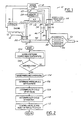
- the engine control unit senses the upstream and downstream temperature of the catalyst 40 in step 100, by way of the upstream and downstream temperature sensors 50, 52 respectively.
- the upstream and downstream temperature sensors 50, 52 aid the engine control unit 18 in determining whether or not reductant is to be injected into the exhaust gas flow.
- the engine control unit 18 determines when it is necessary to add reductant to the exhaust gas flow at step 102.
- thermo sensors 50, 52 alternative exhaust system sensors may be used.
- upstream and downstream NO sensors could be used to directly measure the catalyst conversion efficiency.
- the pressure differential across the chamber 36 and exhaust gas flow 48 is sensed by the differential pressure transducer 46 at step 104, and the signal is supplied to the engine control unit 18. Based on the differential pressure measured in step 104, the engine control unit 18 determines the pressurised air flow rate required for consistent reductant metering and atomisation in step 106. From this step, the duty cycle of the air valve 34 is determined in step 108 as well as the duty cycle of the injector 42 at step 110. Preferably, the engine control unit varies a pulse width modulated (PWM) signal to the air valve 34 to keep the pressure differential as measured by the differential pressure transducer 46 constant.
- PWM pulse width modulated
- the engine control unit 18 then controls the air valve 34 and injector 42 at step 112 in accordance with the duty cycles determined in steps 108 and 110.
- reductant is injected into the chamber 36 by the nozzle 42.
- pressurised air is introduced into the chamber 36 by the air valve 34.
- the atomised reductant and air mixture then travels along the conduit 38 and is introduced into the exhaust gas flow 48 upstream of the catalyst 40.
- the upstream and downstream temperature sensors 50, 52 also serve the additional function of error detection in the exhaust gas purification system 10.
- the temperature sensors 50 and 52 can monitor the temperature rise due to exothermic catalyst reactions and signal malfunctions in the air valve 34, injector 42, or the differential pressure transducer 46.
- the engine control unit 18 preferably maintains the pressure differential as measured by the pressure differential transducer 46 constant, there are times when a lower pressure drop across the transducer 46 is preferred to conserve the pressurised air supply in the reservoir 30. For example, airflow into and out of the chamber 36 is desirable and necessary to ensure that the orifice at the tip of the conduit 38 does not plug with exhaust gas deposits.
- the turbocharger 20 does not necessarily deliver pressurised air to the reservoir 30 at all times. It is, therefore, necessary to meter the pressurised air from the reservoir as economically as possible. Accordingly, the engine control unit senses the exhaust gas temperature from the upstream temperature 50 as well as from engine control sensor 16 such as the engine speed, vehicle speed, and/or accelerator pedal position to infer whether the engine is at idle.
- the engine control unit 18 modulates the PWM signal to air valve 34 to maintain a lower pressure drop across the pressure transducer 46 to conserve the pressurised air supply in the reservoir 30.
Landscapes
- Engineering & Computer Science (AREA)
- Chemical & Material Sciences (AREA)
- Chemical Kinetics & Catalysis (AREA)
- Combustion & Propulsion (AREA)
- Health & Medical Sciences (AREA)
- Environmental & Geological Engineering (AREA)
- Analytical Chemistry (AREA)
- General Chemical & Material Sciences (AREA)
- Oil, Petroleum & Natural Gas (AREA)
- Biomedical Technology (AREA)
- Mechanical Engineering (AREA)
- General Engineering & Computer Science (AREA)
- Toxicology (AREA)
- Exhaust Gas After Treatment (AREA)
Claims (8)
- Abgasreinigungsanlage für einen mit einem Turbolader (20) und einer Abgasleitung ausgestatteten Motor mit einem darin eingebauten Katalysator (40) zur Umsetzung von NOx, umfassend:einen Vorratsbehälter (30) zum Lagern von aus dem Turbolader (20) kommender Druckluft und Mittel zur Förderung von Druckluft aus dem Vorratsbehälter (30) und zur Zuführung derselben in die Abgasleitung, stromaufwärts des Katalysators (40) zur Umsetzung von NOx;eine mit einer Reduktionsmittelversorgung (44) strömungsverbundene Reduktionsmittel-Einspritzvorrichtung (42), wobei die Reduktionsmittel-Einspritzvorrichtung auf ein Einspritzsignal anspricht, um eine Menge an Reduktionsmittel zu zerstäuben und direkt stromaufwärts des Katalysators (40) zur Umsetzung von NOx zur Zuführung desselben in die Abgasleitung einzuspritzen; gekennzeichnet durch eine außerhalb der Abgasleitung befindliche Mischkammer (36), die mit dem Vorratsbehälter (30) strömungsverbunden und mit der Reduktionsmittel-Einspritzvorrichtung (42) verbunden ist, wobei die Mischkammer (36) zur Einbringung einer Menge an Luft- und Reduktionsmittelgemisch in den Abgasfluss stromaufwärts des Katalysators (40) zur Umsetzung von NOx über ein Rohr (38) mit der Abgasleitung strömungsverbunden ist.
- Abgasreinigungsanlage nach Anspruch 1, ferner umfassend ein zwischen dem Vorratsbehälter (30) und der Mischkammer (36) geschaltetes Ventil (34), wobei das Ventil (34) auf ein Ventilsteuerungssignal anspricht, um eine Menge an Druckluft aus dem Vorratsbehälter (30) in die Mischkammer (36) einzubringen.
- Abgasreinigungsanlage nach Anspruch 1, ferner umfassend jeweils stromaufwärts und stromabwärts gelegene, die stromaufwärtige und stromabwärtige Temperatur erfassende Sensoren (50, 52) des Katalysators (40) zur Umsetzung von NOx zur Überwachung der Differenztemperatur in dem Katalysator (40) zur Umsetzung von NOx.
- Abgasreinigungsanlage nach Anspruch 1, ferner umfassend, zur Bestimmung der Leistung des Katalysators (40) bei der Umsetzung von NOx, stromaufwärts bzw. stromabwärts gelegene Sensoren zur Erfassung des stromaufwärtigen bzw. stromabwärtigen NO des Katalysators (40) zur Umsetzung von NOx.
- Abgasreinigungsanlage nach Anspruch 2, ferner umfassend einen zwischen der Mischkammer (36) und der Abgasleitung (48) angeordneten Differenzdruckumformer (46), zur Messung des Differenzdrucks in der Mischkammer (36) und der Abgasleitung (48) stromaufwärts des Katalysators (40) zur Umsetzung von NOx.
- Abgasreinigungsanlage nach Anspruch 5, ferner umfassend ein Motorsteuergerät umfassend einen Mikroprozessor und einen zugeordneten Speicher, wobei das Motorsteuergerät (18) dafür geeignet ist, das Differenzdrucksignal von dem Differenzdruckumformer (46) als Eingabe zu erhalten und das Ventilsteuerungssignal zur Aufrechterhaltung des Differenzdrucks in der Mischkammer (36) und der Abgasleitung (48) stromaufwärts des Katalysators (40) zur Umsetzung von NOx auf einem Sollwert auszugeben.
- Abgasreinigungsanlage nach Anspruch 6, ferner umfassend jeweils stromaufwärts und stromabwärts gelegene Sensoren (50, 52) zur Erfassung der stromaufwärtigen bzw. stromabwärtigen Temperatur des Katalysators (40) zur Umsetzung von NOx, wobei das Motorsteuergerät (18) dafür geeignet ist, die Signale bezüglich der stromaufwärtigen und stromabwärtigen Temperatur von den Sensoren (50, 52) zur Erfassung der stromaufwärtigen bzw. stromabwärtigen Temperatur als Eingabe zu erhalten und zum Erreichen eines gewünschten Grads der NOx-Umsetzung im Katalysator (40) zur Umsetzung von NOx das Ventilsteuerungssignal und das Reduktionsmitteleinspritzsignal auszugeben.
- Verfahren zur Verbesserung der Leistung eines Katalysators (40) zur Umsetzung von NOx, der in der Abgasleitung (48) eines mit einem Turbolader (20) ausgestatteten Motors (12) angeordnet ist, durch Bereitstellen eines Vorratsbehälters (36) zur Lagerung von aus dem Turbolader (20) stammender Druckluft, eines Ventils (34), das mit dem Vorratsbehälter (30) strömungsverbunden ist und auf ein Ventilsteuerungssignal anspricht, einer Reduktionsmittel-Einspritzvorrichtung (42), die mit einer Reduktionsmittelversorgung (44) strömungsverbunden ist und auf ein Einspritzsignal anspricht, einer außerhalb der Abgasleitung (48) befindlichen Mischkammer (36), die mit dem Ventil (34) strömungsverbunden und mit der Reduktionsmittel-Einspritzvorrichtung (42) verbunden ist, wobei die Mischkammer (36) über ein Rohr (38) mit der Abgasleitung (48) strömungsverbunden ist, ein Differenzdruckumformer (46) zwischen der Mischkammer (36) und der Abgasleitung (48) angeordnet ist und ein Sensor (50, 52) zum Erfassen der stromaufwärtigen und der stromabwärtigen Temperatur stromaufwärts bzw. stromabwärts des Katalysators (40) zur Umsetzung von NOx gelegen ist, wobei das Verfahren die folgenden Schritte umfasst:Bestimmen einer Menge an aus dem Vorratsbehälter (30) in die Mischkammer (36) einzubringender Luft;Bestimmen einer Menge an in die Mischkammer (36) einzuspritzendem Reduktionsmittel;Ausgeben des Ventilsteuerungssignals zur Ansteuerung des Ventils (34) zur Zufuhr der gewünschten Menge an Druckluft aus dem Vorratsbehälter (30) in die Mischkammer (36); undAusgeben des Einspritzsignals zur Ansteuerung der Reduktionsmittel-Einspritzvorrichtung (42) zur Zufuhr der gewünschten Menge an Reduktionsmittel in die Mischkammer (36),wobei die Luftmenge derart ist, dass der Druck innerhalb der Mischkammer (36) größer ist als der Druck innerhalb der Abgasleitung (48) stromaufwärts des Katalysators (40) zur Umsetzung von NOx, so dass zum Erreichen eines gewünschten Leistungsgrads des Katalysators die Mischung aus Luft und Reduktionsmittel in die Abgasleitung (48) stromaufwärts des Katalysators (40) zur Umsetzung von NOx eingebracht wird.
Applications Claiming Priority (2)
| Application Number | Priority Date | Filing Date | Title |
|---|---|---|---|
| US468499 | 1999-12-21 | ||
| US09/468,499 US6167698B1 (en) | 1999-12-21 | 1999-12-21 | Exhaust gas purification system for a lean burn engine |
Publications (3)
| Publication Number | Publication Date |
|---|---|
| EP1111211A2 EP1111211A2 (de) | 2001-06-27 |
| EP1111211A3 EP1111211A3 (de) | 2003-08-13 |
| EP1111211B1 true EP1111211B1 (de) | 2006-08-23 |
Family
ID=23860049
Family Applications (1)
| Application Number | Title | Priority Date | Filing Date |
|---|---|---|---|
| EP00311124A Expired - Lifetime EP1111211B1 (de) | 1999-12-21 | 2000-12-13 | Abgasreinigungsanlage einer mit Luftüberschuss arbeitenden Brennkraftmaschine |
Country Status (4)
| Country | Link |
|---|---|
| US (1) | US6167698B1 (de) |
| EP (1) | EP1111211B1 (de) |
| CA (1) | CA2329090A1 (de) |
| DE (1) | DE60030241T2 (de) |
Cited By (2)
| Publication number | Priority date | Publication date | Assignee | Title |
|---|---|---|---|---|
| DE102014010250B3 (de) * | 2014-07-11 | 2015-07-23 | Thomas Magnete Gmbh | Verfahren zur Einspritzung von Flüssigkeit in den Abgasstrang eines Verbrennungsmotors |
| DE102014010249A1 (de) | 2014-07-11 | 2016-01-14 | Thomas Magnete Gmbh | Vorrichtung und Verfahren zur Einspritzung von Flüssigkeit in den Abgasstrang eines Verbrennungsmotors |
Families Citing this family (68)
| Publication number | Priority date | Publication date | Assignee | Title |
|---|---|---|---|---|
| US6470673B1 (en) * | 2000-02-22 | 2002-10-29 | Ford Global Technologies, Inc. | Control of a NOX reductant delivery system |
| US6526746B1 (en) * | 2000-08-02 | 2003-03-04 | Ford Global Technologies, Inc. | On-board reductant delivery assembly |
| US6415602B1 (en) * | 2000-10-16 | 2002-07-09 | Engelhard Corporation | Control system for mobile NOx SCR applications |
| DE10100419A1 (de) * | 2001-01-08 | 2002-07-11 | Bosch Gmbh Robert | Verfahren und Vorrichtung zur Steuerung eines Abgasnachbehandlungssystems |
| DE10127834A1 (de) * | 2001-06-08 | 2002-12-12 | Bosch Gmbh Robert | Vorrichtung und Verfahren zur Dosierung eines Reduktionsmittels zur Entfernung von Stickoxiden aus Abgasen |
| JP4122849B2 (ja) * | 2001-06-22 | 2008-07-23 | 株式会社デンソー | 触媒劣化検出装置 |
| US6928359B2 (en) * | 2001-08-09 | 2005-08-09 | Ford Global Technologies, Llc | High efficiency conversion of nitrogen oxides in an exhaust aftertreatment device at low temperature |
| US7121085B2 (en) * | 2001-09-04 | 2006-10-17 | Ford Global Technologies, Llc | Method and apparatus for controlling hydrocarbon injection into engine exhaust to reduce NOx |
| US6487852B1 (en) * | 2001-09-04 | 2002-12-03 | Ford Global Technologies, Inc. | Method and apparatus for controlling reactant injection into an active lean NOx catalyst |
| DE20119514U1 (de) * | 2001-12-03 | 2002-02-28 | Purem Abgassysteme Gmbh & Co | Reduktionsmitteldosiereinrichtung |
| US20040083722A1 (en) * | 2002-11-06 | 2004-05-06 | Ford Global Technologies, Inc. | Diesel aftertreatment systems |
| US6865881B2 (en) * | 2002-11-18 | 2005-03-15 | Diesel & Combustion Technologies, Llc | System and method for reducing nitrogen oxides in combustion exhaust streams |
| US6834498B2 (en) | 2002-11-21 | 2004-12-28 | Ford Global Technologies, Llc | Diesel aftertreatment systems |
| US6928806B2 (en) * | 2002-11-21 | 2005-08-16 | Ford Global Technologies, Llc | Exhaust gas aftertreatment systems |
| US6862879B2 (en) * | 2002-11-21 | 2005-03-08 | Ford Global Technologies, Llc | Diesel aftertreatment system |
| US6895747B2 (en) | 2002-11-21 | 2005-05-24 | Ford Global Technologies, Llc | Diesel aftertreatment systems |
| US20040237509A1 (en) * | 2003-05-29 | 2004-12-02 | Detroit Diesel Corporation | System and method for supplying clean pressurized air to diesel oxidation catalyst |
| WO2005005797A2 (en) * | 2003-06-12 | 2005-01-20 | Donaldson Company, Inc. | Method of dispensing fuel into transient flow of an exhaust system |
| JP2006527815A (ja) * | 2003-06-18 | 2006-12-07 | ジョンソン、マッセイ、パブリック、リミテッド、カンパニー | 還元体添加の制御方法 |
| JP4152833B2 (ja) * | 2003-07-30 | 2008-09-17 | 日産ディーゼル工業株式会社 | エンジンの排気浄化装置 |
| US7849674B2 (en) * | 2003-09-19 | 2010-12-14 | Nissan Diesel Motor Co., Ltd. | Exhaust emission purifying apparatus for engine |
| EP1691046B1 (de) * | 2003-09-19 | 2013-04-24 | Nissan Diesel Motor Co., Ltd. | Abgasreinigungsvorrichtung für eine brennkraftmaschine |
| US7703276B2 (en) * | 2003-10-02 | 2010-04-27 | Nissan Diesel Motor Co., Ltd. | Exhaust gas purifying apparatus for engine |
| EP1712754A4 (de) * | 2004-02-02 | 2010-09-29 | Nissan Diesel Motor Co | Vorrichtung zur abgasreinigung eines verbrennungsmotors |
| EP2383445B1 (de) * | 2004-02-02 | 2012-12-19 | Nissan Diesel Motor Co., Ltd. | Abgasreinigungsvorrichtung für einen Motor |
| US7776265B2 (en) * | 2004-03-18 | 2010-08-17 | Cummins Filtration Ip, Inc. | System for diagnosing reagent solution quality |
| US7765793B2 (en) * | 2004-04-02 | 2010-08-03 | Komatsu Ltd. | Exhaust emission control device of internal combustion engine |
| JP4204519B2 (ja) * | 2004-06-14 | 2009-01-07 | トヨタ自動車株式会社 | 内燃機関の排気浄化装置 |
| GB0428289D0 (en) * | 2004-12-24 | 2005-01-26 | Johnson Matthey Plc | Reductant addition in exhaust system comprising NOx-absorbent |
| GB0428291D0 (en) * | 2004-12-24 | 2005-01-26 | Johnson Matthey Plc | Methods of regenerating NOx-Absorbent |
| WO2005124114A1 (en) * | 2004-06-18 | 2005-12-29 | Johnson Matthey Public Limited Company | Reductant addition in exhaust system comprising nox-absorbent |
| JP3714559B1 (ja) * | 2004-11-05 | 2005-11-09 | 日産ディーゼル工業株式会社 | 排気浄化装置 |
| US7469679B2 (en) | 2004-12-09 | 2008-12-30 | Caterpillar Inc. | Method for detecting and controlling movement of an actuated component |
| JP2006250117A (ja) * | 2005-03-14 | 2006-09-21 | Nissan Diesel Motor Co Ltd | 排気浄化システムの還元剤噴射状況判定装置 |
| US7464539B2 (en) * | 2005-04-29 | 2008-12-16 | Emcon Technologies Llc | Method and apparatus for supplying air to emission abatement device by use of turbocharger |
| BRPI0520348A2 (pt) * | 2005-07-07 | 2009-05-05 | Volvo Lastvagnar Ab | método, dispositivo e produto de programa de computador para diagnóstico de pelo menos uma unidade de controle de emissão de exaustão |
| US20070068146A1 (en) * | 2005-09-28 | 2007-03-29 | Caterpillar Inc. | Exhaust treatment system having hydraulically-actuated air valve |
| DE102006043099A1 (de) * | 2005-11-14 | 2007-06-28 | Robert Bosch Gmbh | Luftmengensteuerung für eine Einrichtung zur Erzeugung von Reduktionsmittel |
| DE102005062924A1 (de) * | 2005-12-29 | 2007-07-26 | Arvinmeritor Emissions Technologies Gmbh | Abgasanlage für ein Kraftfahrzeug sowie Verfahren zur Regeneration eines Partikelfilters in einer Kfz-Abgasanlage |
| US8156732B2 (en) * | 2006-03-24 | 2012-04-17 | Fleetguard, Inc. | Apparatus, system, and method for regenerating an exhaust gas treatment device |
| JP4280934B2 (ja) * | 2006-06-16 | 2009-06-17 | 株式会社デンソー | 排気浄化装置、添加剤供給装置および内燃機関の排気浄化システム |
| US7587890B2 (en) * | 2006-08-21 | 2009-09-15 | Cummins Inc. | Reductant injection rate shaping method for regeneration of aftertreatment systems |
| JP5008366B2 (ja) * | 2006-09-26 | 2012-08-22 | Udトラックス株式会社 | エンジンの排気浄化装置 |
| US8171721B2 (en) * | 2007-01-22 | 2012-05-08 | International Engine Intellectual Property Company, Llc | Closed loop control of exhaust system fluid dosing |
| US20080271447A1 (en) * | 2007-05-03 | 2008-11-06 | Abel John B | Method and apparatus for supplying air to an emission abatement device by use of a turbocharger |
| US8069651B2 (en) * | 2007-08-30 | 2011-12-06 | Caterpillar Inc. | Machine, engine system and operating method |
| US8056671B2 (en) * | 2007-10-12 | 2011-11-15 | Mazda Motor Corporation | Exhaust-gas purification device disposition structure of vehicle |
| US7971426B2 (en) | 2007-11-01 | 2011-07-05 | Ford Global Technologies, Llc | Reductant injection system diagnostics |
| US7980061B2 (en) * | 2008-03-04 | 2011-07-19 | Tenneco Automotive Operating Company Inc. | Charged air bypass for aftertreatment combustion air supply |
| DE102008001789A1 (de) * | 2008-05-15 | 2009-11-19 | Robert Bosch Gmbh | Verfahren zum Betreiben eines Dosierventils und Vorrichtung zur Durchführung des Verfahrens |
| US20100186382A1 (en) * | 2009-01-26 | 2010-07-29 | Caterpillar Inc. | Emissions system mounting device with reductant mixing |
| US8783022B2 (en) * | 2009-08-17 | 2014-07-22 | Donaldson Company, Inc. | Retrofit aftertreatment system for treating diesel exhaust |
| FR2949812B1 (fr) * | 2009-09-10 | 2012-03-30 | Peugeot Citroen Automobiles Sa | Dispositif et procede de regulation de l'injection d'une quantite de reducteur en phase gaz |
| DE102010007564B4 (de) * | 2010-02-10 | 2022-12-29 | Albonair Gmbh | Dosiersystem zur Eindüsung eines Reduktionsmittels in den Abgasstrom eines Verbrennungsmotors |
| US9145817B2 (en) * | 2010-11-08 | 2015-09-29 | Bosch Corporation | Reducing agent injection valve abnormality detection unit and reducing agent supply apparatus |
| EP2615281A4 (de) * | 2010-12-07 | 2014-05-14 | Toyota Motor Co Ltd | Steuerungsvorrichtung für einen verbrennungsmotor |
| CN105804837B (zh) * | 2011-08-22 | 2018-12-14 | 康明斯排放处理公司 | 具有泄漏旁路的尿素溶液泵 |
| US9021787B2 (en) * | 2012-09-05 | 2015-05-05 | Mi Yan | Fluid delivery apparatus with flow rate sensing means |
| DE102014201709B4 (de) | 2013-02-15 | 2016-12-29 | Ford Global Technologies, Llc | Abgasturboaufgeladene Brennkraftmaschine mit Abgasnachbehandlung und Verfahren zum Betreiben einer derartigen Brennkraftmaschine |
| US9926822B2 (en) * | 2013-08-16 | 2018-03-27 | Cummins Emission Solutions, Inc. | Air curtain for urea mixing chamber |
| JP6090134B2 (ja) * | 2013-12-05 | 2017-03-08 | 株式会社デンソー | 高活性物質添加装置 |
| US9453446B2 (en) | 2014-10-21 | 2016-09-27 | Cummins Emission Solutions, Inc. | Constant mass flow injection system |
| DE112015005872T5 (de) * | 2014-12-31 | 2017-09-14 | Cummins Emission Solutions, Inc. | Direktgekoppeltes einmoduliges Nachbehandlungssystem |
| DE102015005051A1 (de) * | 2015-04-21 | 2016-10-27 | Man Diesel & Turbo Se | System zur Eindüsung von Harnstoff in einen Abgasstrang |
| CH711661A1 (de) * | 2015-10-15 | 2017-04-28 | Liebherr Machines Bulle Sa | Vorrichtung zur Abgasnachbehandlung. |
| US20190195106A1 (en) * | 2017-12-22 | 2019-06-27 | Cummins Emission Solutions Inc. | Systems and methods for air assisted injection of a reductant into an aftertreatment system |
| WO2019207333A1 (en) * | 2018-04-27 | 2019-10-31 | Carrier Corporation | Exhaust back pressure and temperature monitoring transport refrigeration unit |
| EP3721973A1 (de) * | 2019-04-10 | 2020-10-14 | P & F Maschinenbau GmbH | Vorrichtung und verfahren zur herstellung von lackdrähten |
Family Cites Families (19)
| Publication number | Priority date | Publication date | Assignee | Title |
|---|---|---|---|---|
| SE352136B (de) * | 1971-04-05 | 1972-12-18 | Saab Scania Ab | |
| JPS58128413A (ja) | 1982-01-27 | 1983-08-01 | Nissan Motor Co Ltd | 内燃機関の排気浄化装置 |
| JPS5941620A (ja) | 1982-08-31 | 1984-03-07 | Mazda Motor Corp | ディ−ゼルエンジンの排気ガス浄化装置 |
| JPH0621544B2 (ja) | 1983-11-09 | 1994-03-23 | 株式会社日立製作所 | デイ−ゼルエンジン排気浄化装置 |
| DE3730035A1 (de) | 1987-09-08 | 1989-03-16 | Webasto Ag Fahrzeugtechnik | Russfilteranlage im abgastrakt einer diesel-brennkraftmaschine |
| DE3821832C1 (en) * | 1988-06-29 | 1989-11-02 | Krupp Mak Maschinenbau Gmbh, 2300 Kiel, De | Exhaust system for a piston internal combustion engine |
| JPH0623538B2 (ja) | 1989-03-30 | 1994-03-30 | いすゞ自動車株式会社 | パティキュレートトラップの再燃焼装置 |
| JPH0579319A (ja) | 1991-09-20 | 1993-03-30 | Hitachi Ltd | エンジン排気浄化システム |
| JPH0681631A (ja) * | 1992-08-28 | 1994-03-22 | Isuzu Motors Ltd | 内燃機関の排気ガス浄化装置 |
| JP2605556B2 (ja) | 1992-10-13 | 1997-04-30 | トヨタ自動車株式会社 | 内燃機関の排気浄化装置 |
| US5367875A (en) * | 1992-12-07 | 1994-11-29 | Coltec Industries Inc | Automated catalytic reduction system |
| US5544483A (en) * | 1993-02-19 | 1996-08-13 | Volkswagen Ag | Internal combustion engine with a secondary air-fuel supply |
| DE4430965C2 (de) * | 1994-08-31 | 1997-09-11 | Siemens Ag | Verfahren zum Steuern der Kraftstoffzufuhr für eine Brennkraftmaschine mit beheizbarem Katalysator |
| JPH08200047A (ja) * | 1995-01-25 | 1996-08-06 | Nissan Diesel Motor Co Ltd | エンジンの排気浄化装置 |
| DE59600784D1 (de) * | 1995-05-19 | 1998-12-10 | Siemens Ag | Vormischkammer für eine abgas-reinigungsanlage |
| US5653101A (en) * | 1995-06-19 | 1997-08-05 | Caterpillar Inc. | Method for treating an exhaust gas stream for the removal on NOx |
| US6021639A (en) * | 1995-06-28 | 2000-02-08 | Mitsubishi Heavy Industries, Ltd. | Black smoke eliminating device for internal combustion engine and exhaust gas cleaning system including the device |
| DE19531028A1 (de) * | 1995-08-23 | 1997-02-27 | Siemens Ag | Verfahren zur Abgasreinigung und Abgas-Reinigungseinrichtung für einen Verbrennungsmotor |
| DE19736384A1 (de) * | 1997-08-21 | 1999-02-25 | Man Nutzfahrzeuge Ag | Verfahren zur Dosierung eines Reduktionsmittels in stickoxidhaltiges Abgas einer Brennkraftmaschine |
-
1999
- 1999-12-21 US US09/468,499 patent/US6167698B1/en not_active Expired - Fee Related
-
2000
- 2000-12-13 DE DE60030241T patent/DE60030241T2/de not_active Expired - Fee Related
- 2000-12-13 EP EP00311124A patent/EP1111211B1/de not_active Expired - Lifetime
- 2000-12-19 CA CA002329090A patent/CA2329090A1/en not_active Abandoned
Cited By (3)
| Publication number | Priority date | Publication date | Assignee | Title |
|---|---|---|---|---|
| DE102014010250B3 (de) * | 2014-07-11 | 2015-07-23 | Thomas Magnete Gmbh | Verfahren zur Einspritzung von Flüssigkeit in den Abgasstrang eines Verbrennungsmotors |
| DE102014010249A1 (de) | 2014-07-11 | 2016-01-14 | Thomas Magnete Gmbh | Vorrichtung und Verfahren zur Einspritzung von Flüssigkeit in den Abgasstrang eines Verbrennungsmotors |
| DE102014010249B4 (de) * | 2014-07-11 | 2017-04-20 | Thomas Magnete Gmbh | Vorrichtung zur Einspritzung von Flüssigkeit in den Abgasstrang eines Verbrennungsmotors |
Also Published As
| Publication number | Publication date |
|---|---|
| EP1111211A2 (de) | 2001-06-27 |
| EP1111211A3 (de) | 2003-08-13 |
| US6167698B1 (en) | 2001-01-02 |
| CA2329090A1 (en) | 2001-06-21 |
| DE60030241T2 (de) | 2007-01-11 |
| DE60030241D1 (de) | 2006-10-05 |
Similar Documents
| Publication | Publication Date | Title |
|---|---|---|
| EP1111211B1 (de) | Abgasreinigungsanlage einer mit Luftüberschuss arbeitenden Brennkraftmaschine | |
| EP1431533B1 (de) | Emissionssteuerungssystem zur Erhöhung der Leistungfähigkeit einer selektiven katalytischen Reduktion | |
| US7475535B2 (en) | Diesel aftertreatment systems | |
| US6173568B1 (en) | Method and device for operating an internal combustion engine operating with an excess of air | |
| US7842267B2 (en) | Exhaust emission purifying apparatus for engine | |
| CN102312712B (zh) | 确定选择催化还原催化剂的老化并控制其的系统和方法 | |
| US8745973B2 (en) | System and method for controlling reducing agent injection in a selective catalytic reduction system | |
| US10196952B2 (en) | Vehicle exhaust system having variable exhaust treatment injector system | |
| US20080178575A1 (en) | System and Method for Monitoring Reductant Quality | |
| CN100526617C (zh) | 用于内燃机的废气排放控制装置 | |
| US20090104085A1 (en) | Reducing agent spray control system ensuring operation efficiency | |
| US20090223207A1 (en) | Pertubation control strategy for low-temperature urea scr nox reduction | |
| CN101769190B (zh) | 还原剂喷射器的热保护系统 | |
| GB2352651A (en) | Emission control system | |
| CN101646846A (zh) | 氨氧化催化剂中的n2o生成量推定方法以及内燃机的排气净化系统 | |
| US9334774B2 (en) | Control system and method for preventing hydrocarbon slip during particulate matter filter regeneration | |
| EP1176289B1 (de) | Abgasemissions-Steuerungssystem für Verbrennungsmotoren | |
| US20050066652A1 (en) | Diesel aftertreatment systems | |
| US6862879B2 (en) | Diesel aftertreatment system | |
| CN108571364B (zh) | 选择性催化还原效率确定 | |
| EP2857647B1 (de) | Abgasreinigungsvorrichtung für einen verbrennungsmotor | |
| US20040098976A1 (en) | Diesel aftertreatment systems | |
| WO2014049350A1 (en) | Exhaust system | |
| US11629625B1 (en) | Systems and methods of engine exhaust air injection before and after catalytic converters | |
| JP3153661B2 (ja) | ディーゼル機関の排気浄化装置 |
Legal Events
| Date | Code | Title | Description |
|---|---|---|---|
| PUAI | Public reference made under article 153(3) epc to a published international application that has entered the european phase |
Free format text: ORIGINAL CODE: 0009012 |
|
| AK | Designated contracting states |
Kind code of ref document: A2 Designated state(s): AT BE CH CY DE DK ES FI FR GB GR IE IT LI LU MC NL PT SE TR |
|
| AX | Request for extension of the european patent |
Free format text: AL;LT;LV;MK;RO;SI |
|
| PUAL | Search report despatched |
Free format text: ORIGINAL CODE: 0009013 |
|
| AK | Designated contracting states |
Designated state(s): AT BE CH CY DE DK ES FI FR GB GR IE IT LI LU MC NL PT SE TR |
|
| AX | Request for extension of the european patent |
Extension state: AL LT LV MK RO SI |
|
| 17P | Request for examination filed |
Effective date: 20031223 |
|
| 17Q | First examination report despatched |
Effective date: 20040224 |
|
| AKX | Designation fees paid |
Designated state(s): DE GB SE |
|
| GRAP | Despatch of communication of intention to grant a patent |
Free format text: ORIGINAL CODE: EPIDOSNIGR1 |
|
| GRAS | Grant fee paid |
Free format text: ORIGINAL CODE: EPIDOSNIGR3 |
|
| GRAA | (expected) grant |
Free format text: ORIGINAL CODE: 0009210 |
|
| AK | Designated contracting states |
Kind code of ref document: B1 Designated state(s): DE GB SE |
|
| REG | Reference to a national code |
Ref country code: GB Ref legal event code: FG4D |
|
| REF | Corresponds to: |
Ref document number: 60030241 Country of ref document: DE Date of ref document: 20061005 Kind code of ref document: P |
|
| REG | Reference to a national code |
Ref country code: GB Ref legal event code: 732E |
|
| PGFP | Annual fee paid to national office [announced via postgrant information from national office to epo] |
Ref country code: GB Payment date: 20061106 Year of fee payment: 7 |
|
| PG25 | Lapsed in a contracting state [announced via postgrant information from national office to epo] |
Ref country code: SE Free format text: LAPSE BECAUSE OF FAILURE TO SUBMIT A TRANSLATION OF THE DESCRIPTION OR TO PAY THE FEE WITHIN THE PRESCRIBED TIME-LIMIT Effective date: 20061123 |
|
| PGFP | Annual fee paid to national office [announced via postgrant information from national office to epo] |
Ref country code: DE Payment date: 20061229 Year of fee payment: 7 |
|
| PLBE | No opposition filed within time limit |
Free format text: ORIGINAL CODE: 0009261 |
|
| STAA | Information on the status of an ep patent application or granted ep patent |
Free format text: STATUS: NO OPPOSITION FILED WITHIN TIME LIMIT |
|
| 26N | No opposition filed |
Effective date: 20070524 |
|
| GBPC | Gb: european patent ceased through non-payment of renewal fee |
Effective date: 20071213 |
|
| PG25 | Lapsed in a contracting state [announced via postgrant information from national office to epo] |
Ref country code: DE Free format text: LAPSE BECAUSE OF NON-PAYMENT OF DUE FEES Effective date: 20080701 |
|
| PG25 | Lapsed in a contracting state [announced via postgrant information from national office to epo] |
Ref country code: GB Free format text: LAPSE BECAUSE OF NON-PAYMENT OF DUE FEES Effective date: 20071213 |