EP1111211B1 - Exhaust gas purification system for a lean burn engine - Google Patents
Exhaust gas purification system for a lean burn engine Download PDFInfo
- Publication number
- EP1111211B1 EP1111211B1 EP00311124A EP00311124A EP1111211B1 EP 1111211 B1 EP1111211 B1 EP 1111211B1 EP 00311124 A EP00311124 A EP 00311124A EP 00311124 A EP00311124 A EP 00311124A EP 1111211 B1 EP1111211 B1 EP 1111211B1
- Authority
- EP
- European Patent Office
- Prior art keywords
- upstream
- mixing chamber
- reductant
- exhaust pipe
- conversion catalyst
- Prior art date
- Legal status (The legal status is an assumption and is not a legal conclusion. Google has not performed a legal analysis and makes no representation as to the accuracy of the status listed.)
- Expired - Lifetime
Links
Images
Classifications
-
- F—MECHANICAL ENGINEERING; LIGHTING; HEATING; WEAPONS; BLASTING
- F01—MACHINES OR ENGINES IN GENERAL; ENGINE PLANTS IN GENERAL; STEAM ENGINES
- F01N—GAS-FLOW SILENCERS OR EXHAUST APPARATUS FOR MACHINES OR ENGINES IN GENERAL; GAS-FLOW SILENCERS OR EXHAUST APPARATUS FOR INTERNAL COMBUSTION ENGINES
- F01N3/00—Exhaust or silencing apparatus having means for purifying, rendering innocuous, or otherwise treating exhaust
- F01N3/08—Exhaust or silencing apparatus having means for purifying, rendering innocuous, or otherwise treating exhaust for rendering innocuous
- F01N3/10—Exhaust or silencing apparatus having means for purifying, rendering innocuous, or otherwise treating exhaust for rendering innocuous by thermal or catalytic conversion of noxious components of exhaust
- F01N3/18—Exhaust or silencing apparatus having means for purifying, rendering innocuous, or otherwise treating exhaust for rendering innocuous by thermal or catalytic conversion of noxious components of exhaust characterised by methods of operation; Control
- F01N3/20—Exhaust or silencing apparatus having means for purifying, rendering innocuous, or otherwise treating exhaust for rendering innocuous by thermal or catalytic conversion of noxious components of exhaust characterised by methods of operation; Control specially adapted for catalytic conversion ; Methods of operation or control of catalytic converters
- F01N3/2066—Selective catalytic reduction [SCR]
-
- B—PERFORMING OPERATIONS; TRANSPORTING
- B01—PHYSICAL OR CHEMICAL PROCESSES OR APPARATUS IN GENERAL
- B01D—SEPARATION
- B01D53/00—Separation of gases or vapours; Recovering vapours of volatile solvents from gases; Chemical or biological purification of waste gases, e.g. engine exhaust gases, smoke, fumes, flue gases, aerosols
- B01D53/34—Chemical or biological purification of waste gases
- B01D53/92—Chemical or biological purification of waste gases of engine exhaust gases
- B01D53/94—Chemical or biological purification of waste gases of engine exhaust gases by catalytic processes
- B01D53/9404—Removing only nitrogen compounds
- B01D53/9409—Nitrogen oxides
- B01D53/9431—Processes characterised by a specific device
-
- B—PERFORMING OPERATIONS; TRANSPORTING
- B01—PHYSICAL OR CHEMICAL PROCESSES OR APPARATUS IN GENERAL
- B01D—SEPARATION
- B01D53/00—Separation of gases or vapours; Recovering vapours of volatile solvents from gases; Chemical or biological purification of waste gases, e.g. engine exhaust gases, smoke, fumes, flue gases, aerosols
- B01D53/34—Chemical or biological purification of waste gases
- B01D53/92—Chemical or biological purification of waste gases of engine exhaust gases
- B01D53/94—Chemical or biological purification of waste gases of engine exhaust gases by catalytic processes
- B01D53/9495—Controlling the catalytic process
-
- F—MECHANICAL ENGINEERING; LIGHTING; HEATING; WEAPONS; BLASTING
- F02—COMBUSTION ENGINES; HOT-GAS OR COMBUSTION-PRODUCT ENGINE PLANTS
- F02B—INTERNAL-COMBUSTION PISTON ENGINES; COMBUSTION ENGINES IN GENERAL
- F02B37/00—Engines characterised by provision of pumps driven at least for part of the time by exhaust
- F02B37/12—Control of the pumps
- F02B37/16—Control of the pumps by bypassing charging air
- F02B37/164—Control of the pumps by bypassing charging air the bypassed air being used in an auxiliary apparatus, e.g. in an air turbine
-
- F—MECHANICAL ENGINEERING; LIGHTING; HEATING; WEAPONS; BLASTING
- F01—MACHINES OR ENGINES IN GENERAL; ENGINE PLANTS IN GENERAL; STEAM ENGINES
- F01N—GAS-FLOW SILENCERS OR EXHAUST APPARATUS FOR MACHINES OR ENGINES IN GENERAL; GAS-FLOW SILENCERS OR EXHAUST APPARATUS FOR INTERNAL COMBUSTION ENGINES
- F01N2610/00—Adding substances to exhaust gases
- F01N2610/02—Adding substances to exhaust gases the substance being ammonia or urea
-
- F—MECHANICAL ENGINEERING; LIGHTING; HEATING; WEAPONS; BLASTING
- F01—MACHINES OR ENGINES IN GENERAL; ENGINE PLANTS IN GENERAL; STEAM ENGINES
- F01N—GAS-FLOW SILENCERS OR EXHAUST APPARATUS FOR MACHINES OR ENGINES IN GENERAL; GAS-FLOW SILENCERS OR EXHAUST APPARATUS FOR INTERNAL COMBUSTION ENGINES
- F01N2610/00—Adding substances to exhaust gases
- F01N2610/03—Adding substances to exhaust gases the substance being hydrocarbons, e.g. engine fuel
-
- F—MECHANICAL ENGINEERING; LIGHTING; HEATING; WEAPONS; BLASTING
- F01—MACHINES OR ENGINES IN GENERAL; ENGINE PLANTS IN GENERAL; STEAM ENGINES
- F01N—GAS-FLOW SILENCERS OR EXHAUST APPARATUS FOR MACHINES OR ENGINES IN GENERAL; GAS-FLOW SILENCERS OR EXHAUST APPARATUS FOR INTERNAL COMBUSTION ENGINES
- F01N2610/00—Adding substances to exhaust gases
- F01N2610/08—Adding substances to exhaust gases with prior mixing of the substances with a gas, e.g. air
-
- F—MECHANICAL ENGINEERING; LIGHTING; HEATING; WEAPONS; BLASTING
- F01—MACHINES OR ENGINES IN GENERAL; ENGINE PLANTS IN GENERAL; STEAM ENGINES
- F01N—GAS-FLOW SILENCERS OR EXHAUST APPARATUS FOR MACHINES OR ENGINES IN GENERAL; GAS-FLOW SILENCERS OR EXHAUST APPARATUS FOR INTERNAL COMBUSTION ENGINES
- F01N3/00—Exhaust or silencing apparatus having means for purifying, rendering innocuous, or otherwise treating exhaust
- F01N3/08—Exhaust or silencing apparatus having means for purifying, rendering innocuous, or otherwise treating exhaust for rendering innocuous
- F01N3/0807—Exhaust or silencing apparatus having means for purifying, rendering innocuous, or otherwise treating exhaust for rendering innocuous by using absorbents or adsorbents
-
- Y—GENERAL TAGGING OF NEW TECHNOLOGICAL DEVELOPMENTS; GENERAL TAGGING OF CROSS-SECTIONAL TECHNOLOGIES SPANNING OVER SEVERAL SECTIONS OF THE IPC; TECHNICAL SUBJECTS COVERED BY FORMER USPC CROSS-REFERENCE ART COLLECTIONS [XRACs] AND DIGESTS
- Y02—TECHNOLOGIES OR APPLICATIONS FOR MITIGATION OR ADAPTATION AGAINST CLIMATE CHANGE
- Y02T—CLIMATE CHANGE MITIGATION TECHNOLOGIES RELATED TO TRANSPORTATION
- Y02T10/00—Road transport of goods or passengers
- Y02T10/10—Internal combustion engine [ICE] based vehicles
- Y02T10/12—Improving ICE efficiencies
Landscapes
- Engineering & Computer Science (AREA)
- Chemical & Material Sciences (AREA)
- Chemical Kinetics & Catalysis (AREA)
- Combustion & Propulsion (AREA)
- Health & Medical Sciences (AREA)
- Environmental & Geological Engineering (AREA)
- Analytical Chemistry (AREA)
- General Chemical & Material Sciences (AREA)
- Oil, Petroleum & Natural Gas (AREA)
- Biomedical Technology (AREA)
- Mechanical Engineering (AREA)
- General Engineering & Computer Science (AREA)
- Toxicology (AREA)
- Exhaust Gas After Treatment (AREA)
Description
- The present invention relates generally to exhaust systems for engines and, more particularly, to an exhaust after-treatment system for a low emission, lean-burn internal combustion engine.
- Catalysts are generally used as a means for removing pollutants such a HC, CO and NOx from the exhaust gas of internal combustion engines. The ability of a catalyst to remove NOx in the exhaust gas falls rapidly, however, when the air-fuel ratio of the exhaust gas becomes leaner. Lean burn engines such as diesel engines, operate at overall air-fuel ratios leaner than stoichiometry. As a result, they have improved fuel economy. On the other hand, conventional three-way catalysts do not function properly at such lean air-fuel ratios because of the relatively high concentration of oxygen in the exhaust gas. For this reason, such engines are typically equipped with a lean NOx catalyst (LNC) and/or a selective catalytic reduction (SCR) catalyst.
- LNC and SCR catalyst can chemically reduce NOx into the components of CO2, H2O, and N2 by utilising hydrocarbons in the exhaust gas stream. To increase the NOx conversion efficiency of such exhaust gas after-treatment systems, injectors are used to inject reductants such as gasoline, diesel fuel or urea into the exhaust gas upstream of the catalyst.
- The quantity of reductant injected is very small, and must be finely atomised prior to introduction in the exhaust gas flow upstream of the LNC or SRC. Conventional reductant injection systems utilise an air assisted injector in connection with a series of electrically or mechanically driven air and reductant pumps to introduce the air/reductant into the exhaust stream. Such systems have the obvious drawback of additional cost, noise and weight associated with the separate dedicated electrical or mechanical air and reductant pump system.
- JP08200047A describes an exhaust gas purification system for an engine (1) equipped with a turbocharger (3) and an exhaust pipe (5) having a Nox conversion catalyst (6) therein, the system comprising: a reservoir (17) for storing pressurised air received from the turbocharger (3) and being in direct fluid communication with exhaust pipe upstream of the catalyst (6); a reductant injector (7) in fluid communication with a reductant supply (9), the reductant injector (7) being responsive to an injection signal for atomising and injecting a quantity of reductant directly into the exhaust pipe (5) upstream of the catalyst (6) where it mixes with the pressurised air.
- According to the present invention we provide an exhaust gas purification system for an engine equipped with a turbocharger and an exhaust pipe having a NOx conversion catalyst therein, the system comprising: a reservoir for storing pressurised air received from the turbocharger and means for conveying pressurised air from the reservoir for supply to the exhaust pipe upstream of the catalyst; a reductant injector in fluid communication with a reductant supply, the reductant injector responsive to an injection signal for atomising and injecting a quantity of reductant for supply to the exhaust pipe upstream of the catalyst; characterised by a mixing chamber located externally of the exhaust pipe in fluid communication with the reservoir and connected to the reductant injector, the mixing chamber being in fluid communication via a conduit with the exhaust pipe for introducing a quantity of air and reductant mixture into the exhaust gas flow upstream of the NOx conversion catalyst.
- In one embodiment of the invention, the system includes an engine control unit, a valve connected between the reservoir and the mixing chamber, and a differential pressure transducer positioned between the mixing chamber and the exhaust pipe for measuring the pressure differential across the mixing chamber and exhaust pipe upstream of the NOx conversion catalyst. The engine control unit controls the valve to introduce a quantity of pressurised air from the reservoir into the mixing chamber to maintain the pressure differential between the mixing chamber and exhaust pipe substantially constant.
- One advantage of the present invention is that it eliminates the cost, weight, and durability concerns associated with a separate dedicated electrically or mechanically driven air pump.
- The present invention will now be described further, by way of example, with reference to the accompanying drawings, in which:
- Figure 1 is a schematic view of an exhaust system according to one embodiment of the present invention illustrating its operational relationship with an internal combustion engine; and
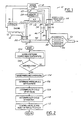
- Figure 2 is a logic flow diagram describing one method of operating the exhaust gas purification system of Figure 1.
- Turning now to Figure 1, an exhaust
gas purification system 10 is illustrated in operational relationship with a lean burninternal combustion engine 12 such as a direct injected diesel engine for an automotive vehicle. Theengine 12 has anexhaust manifold 14 to direct the exhaust gases from theengine 12 through theturbocharger 20, to theexhaust system 10. - The
engine 12 includes sensors, indicated generally at 16, for providing information about engine performance to theengine control unit 18. Such information includes the crankshaft position, camshaft position, accelerator pedal position, air temperature, engine coolant temperature, etc. The information from thesensors 16 is used by theengine control unit 18 to control operation of theengine 12. - The
engine 12 further includes aturbocharger 20 for increasing the intake airflow and pressure supplied to the cylinders of theengine 12. - The exhaust
gas purification system 10 is coupled to theturbocharger 20 by way of anexhaust flange 15. - The
engine control unit 18 is preferably a microprocessor-based controller which provides integrated control of theengine 12 and exhaustgas purification system 10, among other things. Of course, the present invention may be implemented in a separate controller depending upon the particular application. Theengine control unit 18 includes amicroprocessor 22 in communication with input ports and output ports and associatedmemory 24. Thememory 24 may include various types of volatile and non-volatile memory such as random access memory (RAM), read-only memory (ROM), and keep-alive memory (KAM). These functional descriptions of the various types of volatile and non-volatile storage may be implemented by a number of known physical devices including but not limited to EPROMs, EEPROMs, PROMs, flash memory, and the like. - The exhaust gas purification system further includes a
reservoir 30 which receives pressurised air from thecompressor portion 31 of theengine turbocharger 20. Acheck valve 32 prevents the pressurised air from bleeding out of thereservoir 30 and back into theturbocharger 20. Anair valve 34 delivers pressurised air from thereservoir 30 into a chamber 36. Apassage 38 provides a conduit through which the pressurised air and reductant is introduced into the exhaust gas flow upstream of the LNC orSCR 40. - Reductant is introduced into the chamber 36 by the
injector 42 which is supplied from areductant supply system 44. Adifferential pressure transducer 46 senses the pressure differential between the chamber 36 andexhaust gas flow 48. This signal is supplied to theengine control unit 18 for use in activating theinjector 42 andair valve 34. - An
upstream temperature sensor 50 anddownstream temperature sensor 52 are also provided upstream and downstream of the LNC orSCR 40, and communicate temperature information to theengine control unit 18. - The operation of the exhaust gas purification system will now be described with reference to Figures 1 and 2. Pressurised air from the
turbocharger compressor 31 fills thereservoir 30. Thecheck valve 32 keeps the pressurised air from bleeding out of the reservoir and back into thecompressor 31. As shown in Figure 2, the engine control unit senses the upstream and downstream temperature of thecatalyst 40 instep 100, by way of the upstream anddownstream temperature sensors downstream temperature sensors engine control unit 18 in determining whether or not reductant is to be injected into the exhaust gas flow. For example, there are times such engine cold start operation, or extended idle, when thecatalyst 40 is relatively cool and outside its prime operating mode and does not require reductant injection because of the relatively higher concentrations of unburned hydrocarbons in the exhaust gas flow. By known methods, theengine control unit 18 determines when it is necessary to add reductant to the exhaust gas flow atstep 102. - Although the preferred system includes
temperature sensors - The pressure differential across the chamber 36 and
exhaust gas flow 48 is sensed by thedifferential pressure transducer 46 atstep 104, and the signal is supplied to theengine control unit 18. Based on the differential pressure measured instep 104, theengine control unit 18 determines the pressurised air flow rate required for consistent reductant metering and atomisation instep 106. From this step, the duty cycle of theair valve 34 is determined instep 108 as well as the duty cycle of theinjector 42 at step 110. Preferably, the engine control unit varies a pulse width modulated (PWM) signal to theair valve 34 to keep the pressure differential as measured by thedifferential pressure transducer 46 constant. - The
engine control unit 18 then controls theair valve 34 andinjector 42 atstep 112 in accordance with the duty cycles determined insteps 108 and 110. Upon activation, reductant is injected into the chamber 36 by thenozzle 42. At the same time, pressurised air is introduced into the chamber 36 by theair valve 34. The atomised reductant and air mixture then travels along theconduit 38 and is introduced into theexhaust gas flow 48 upstream of thecatalyst 40. - The upstream and
downstream temperature sensors gas purification system 10. For example, thetemperature sensors air valve 34,injector 42, or thedifferential pressure transducer 46. - Although the
engine control unit 18 preferably maintains the pressure differential as measured by the pressuredifferential transducer 46 constant, there are times when a lower pressure drop across thetransducer 46 is preferred to conserve the pressurised air supply in thereservoir 30. For example, airflow into and out of the chamber 36 is desirable and necessary to ensure that the orifice at the tip of theconduit 38 does not plug with exhaust gas deposits. However, theturbocharger 20 does not necessarily deliver pressurised air to thereservoir 30 at all times. It is, therefore, necessary to meter the pressurised air from the reservoir as economically as possible. Accordingly, the engine control unit senses the exhaust gas temperature from theupstream temperature 50 as well as fromengine control sensor 16 such as the engine speed, vehicle speed, and/or accelerator pedal position to infer whether the engine is at idle. While the engine is at idle or under conditions where reductant delivery is not required such as cold start operation, theengine control unit 18 modulates the PWM signal toair valve 34 to maintain a lower pressure drop across thepressure transducer 46 to conserve the pressurised air supply in thereservoir 30.
Claims (8)
- An exhaust gas purification system for an engine equipped with a turbocharger (20) and an exhaust pipe having a NOx conversion catalyst (40) therein, the system comprising:a reservoir (30) for storing pressurised air received from the turbocharger (20) and means for conveying pressurised air from the reservoir (30) for supply to the exhaust pipe upstream of the NOx conversion catalyst (40);a reductant injector (42) in fluid communication with a reductant supply (44), the reductant injector (42) responsive to an injection signal for atomising and injecting a quantity of reductant for supply to the exhaust pipe upstream of the NOx conversion catalyst (40);characterised by a mixing chamber (36) located externally of the exhaust pipe in fluid communication with the reservoir (30) and connected to the reductant injector (42), the mixing chamber (36) being in fluid communication via a conduit (38) with the exhaust pipe for introducing a quantity of air and reductant mixture into the exhaust gas flow upstream of the Nox conversion catalyst (40).
- An exhaust gas purification system as claimed in claim 1 further comprising a valve (34) connected between the reservoir (30) and the mixing chamber (36), the valve (34) responsive to a valve control signal for introducing a quantity of pressurised air from the reservoir (30) into the mixing chamber (36).
- An exhaust gas purification system as claimed in claim 1 further comprising upstream and downstream temperature sensors (50,52) located upstream and downstream, respectively, of the NOx conversion catalyst (40) for monitoring the temperature differential across the NOx conversion catalyst (40).
- An exhaust gas purification system as claimed in claim 1 further comprising downstream NO sensors located upstream and downstream, respectively, of the NOx conversion catalyst (40) for determining the conversion efficiency of the NOx conversion catalyst (40).
- An exhaust gas purification system as claimed in claim 2 further comprising a differential pressure transducer (46) positioned between the mixing chamber (36) and the exhaust pipe (48) for measuring the pressure differential across the mixing chamber (36) and exhaust pipe (48) upstream of the NOx conversion catalyst (40).
- An exhaust gas purification system as claimed in claim 5 further comprising an engine control unit including a microprocessor and associated memory, the engine control unit (18) adapted to receive as an input the pressure differential signal from the differential pressure transducer (46) and output the valve control signal to maintain the pressure differential across the mixing chamber (36) and exhaust pipe (48) upstream of the NOx conversion catalyst (40) substantially at a desired value.
- An exhaust gas purification system as claimed in claim 6 further comprising upstream and downstream temperature sensors located upstream and downstream, respectively, of the NOx conversion catalyst (40), the engine control unit (18) being adapted to receive as inputs the upstream and downstream temperature signal from the upstream and downstream temperature sensors (50, 52), respectively, and output the valve control signal and reductant injection signal to achieve a desired level of NOx conversion in the NOx conversion catalyst (40).
- A method for improving the efficiency of a NOx conversion catalyst (40) located in the exhaust pipe (48) of an engine (12) equipped with a turbocharger (20) by providing a reservoir (36) for storing pressurised air received from the turbocharger (20), a valve (34) in fluid communication with the reservoir (30) and responsive to a valve control signal, a reductant injector (42) in fluid communication with a reductant supply (44) and responsive to an injection signal, a mixing chamber (36) located externally of the exhaust pipe (48) in fluid communication with the valve (34) and connected to the reductant injector (42), the mixing chamber in fluid communication via a conduit (38) with the exhaust pipe (48), a differential pressure transducer (46) positioned between the mixing chamber (36) and the exhaust pipe (48), and an upstream and downstream temperature sensor (50, 52) located upstream and downstream, respectively, of the NOx conversion catalyst (40), the method comprising the steps of:determining a quantity of air to introduce into the mixing chamber (36) from the reservoir (30);determining a quantity of reductant to be injected into the mixing chamber (36);outputting the valve control signal to activate the valve (34) to deliver the desired quantity of pressurised air from the reservoir (30) to the mixing chamber (36); andoutputting the injection signal to activate the reductant injector (42) to deliver the desired quantity of reductant to the mixing chamber (36),the quantity of air being such that the pressure within the mixing chamber (36) is greater than pressure within the exhaust pipe (48) upstream of the NOx convention catalyst (40) such that the air/reductant mixture is introduced into the exhaust pipe (48) upstream of the NOx conversion catalyst (40) to achieve a desired level of catalyst efficiency.
Applications Claiming Priority (2)
| Application Number | Priority Date | Filing Date | Title |
|---|---|---|---|
| US468499 | 1999-12-21 | ||
| US09/468,499 US6167698B1 (en) | 1999-12-21 | 1999-12-21 | Exhaust gas purification system for a lean burn engine |
Publications (3)
| Publication Number | Publication Date |
|---|---|
| EP1111211A2 EP1111211A2 (en) | 2001-06-27 |
| EP1111211A3 EP1111211A3 (en) | 2003-08-13 |
| EP1111211B1 true EP1111211B1 (en) | 2006-08-23 |
Family
ID=23860049
Family Applications (1)
| Application Number | Title | Priority Date | Filing Date |
|---|---|---|---|
| EP00311124A Expired - Lifetime EP1111211B1 (en) | 1999-12-21 | 2000-12-13 | Exhaust gas purification system for a lean burn engine |
Country Status (4)
| Country | Link |
|---|---|
| US (1) | US6167698B1 (en) |
| EP (1) | EP1111211B1 (en) |
| CA (1) | CA2329090A1 (en) |
| DE (1) | DE60030241T2 (en) |
Cited By (2)
| Publication number | Priority date | Publication date | Assignee | Title |
|---|---|---|---|---|
| DE102014010250B3 (en) * | 2014-07-11 | 2015-07-23 | Thomas Magnete Gmbh | Method for injecting liquid into the exhaust gas line of an internal combustion engine |
| DE102014010249A1 (en) | 2014-07-11 | 2016-01-14 | Thomas Magnete Gmbh | Apparatus and method for injecting liquid into the exhaust line of an internal combustion engine |
Families Citing this family (68)
| Publication number | Priority date | Publication date | Assignee | Title |
|---|---|---|---|---|
| US6470673B1 (en) * | 2000-02-22 | 2002-10-29 | Ford Global Technologies, Inc. | Control of a NOX reductant delivery system |
| US6526746B1 (en) * | 2000-08-02 | 2003-03-04 | Ford Global Technologies, Inc. | On-board reductant delivery assembly |
| US6415602B1 (en) * | 2000-10-16 | 2002-07-09 | Engelhard Corporation | Control system for mobile NOx SCR applications |
| DE10100419A1 (en) * | 2001-01-08 | 2002-07-11 | Bosch Gmbh Robert | Method and device for controlling an exhaust gas aftertreatment system |
| DE10127834A1 (en) * | 2001-06-08 | 2002-12-12 | Bosch Gmbh Robert | Device for dosing a reducing agent, especially urea or a urea-water solution, comprises units for introducing the agent into a catalyst arrangement, a dosing valve arranged at the end |
| JP4122849B2 (en) * | 2001-06-22 | 2008-07-23 | 株式会社デンソー | Catalyst degradation detector |
| US6928359B2 (en) * | 2001-08-09 | 2005-08-09 | Ford Global Technologies, Llc | High efficiency conversion of nitrogen oxides in an exhaust aftertreatment device at low temperature |
| US6487852B1 (en) * | 2001-09-04 | 2002-12-03 | Ford Global Technologies, Inc. | Method and apparatus for controlling reactant injection into an active lean NOx catalyst |
| US7121085B2 (en) * | 2001-09-04 | 2006-10-17 | Ford Global Technologies, Llc | Method and apparatus for controlling hydrocarbon injection into engine exhaust to reduce NOx |
| DE20119514U1 (en) * | 2001-12-03 | 2002-02-28 | Purem Abgassysteme Gmbh & Co | Reduktionsmitteldosiereinrichtung |
| US20040083722A1 (en) * | 2002-11-06 | 2004-05-06 | Ford Global Technologies, Inc. | Diesel aftertreatment systems |
| US6865881B2 (en) * | 2002-11-18 | 2005-03-15 | Diesel & Combustion Technologies, Llc | System and method for reducing nitrogen oxides in combustion exhaust streams |
| US6834498B2 (en) * | 2002-11-21 | 2004-12-28 | Ford Global Technologies, Llc | Diesel aftertreatment systems |
| US6895747B2 (en) | 2002-11-21 | 2005-05-24 | Ford Global Technologies, Llc | Diesel aftertreatment systems |
| US6928806B2 (en) * | 2002-11-21 | 2005-08-16 | Ford Global Technologies, Llc | Exhaust gas aftertreatment systems |
| US6862879B2 (en) * | 2002-11-21 | 2005-03-08 | Ford Global Technologies, Llc | Diesel aftertreatment system |
| US20040237509A1 (en) * | 2003-05-29 | 2004-12-02 | Detroit Diesel Corporation | System and method for supplying clean pressurized air to diesel oxidation catalyst |
| US7337607B2 (en) * | 2003-06-12 | 2008-03-04 | Donaldson Company, Inc. | Method of dispensing fuel into transient flow of an exhaust system |
| DE602004006415T2 (en) * | 2003-06-18 | 2008-01-10 | Johnson Matthey Public Ltd., Co. | PROCESS FOR CONTROLLING THE REDUCTION ADDITIVE |
| JP4152833B2 (en) * | 2003-07-30 | 2008-09-17 | 日産ディーゼル工業株式会社 | Engine exhaust purification system |
| EP2426329B1 (en) * | 2003-09-19 | 2013-05-01 | Nissan Diesel Motor Co., Ltd. | Exhaust gas purification device of engine |
| EP1691046B1 (en) * | 2003-09-19 | 2013-04-24 | Nissan Diesel Motor Co., Ltd. | Exhaust emission purification apparatus for an internal combustion engine |
| ATE520868T1 (en) * | 2003-10-02 | 2011-09-15 | Nissan Diesel Motor Co | EMISSION CLEANER FOR ENGINE |
| WO2005073529A1 (en) * | 2004-02-02 | 2005-08-11 | Nissan Diesel Motor Co., Ltd. | Device for purifying exhaust gas of engine |
| WO2005073527A1 (en) * | 2004-02-02 | 2005-08-11 | Nissan Diesel Motor Co., Ltd. | Device for purifying exhaust gas of internal combustion engine |
| US7776265B2 (en) * | 2004-03-18 | 2010-08-17 | Cummins Filtration Ip, Inc. | System for diagnosing reagent solution quality |
| KR100787484B1 (en) * | 2004-04-02 | 2007-12-21 | 가부시키가이샤 고마쓰 세이사쿠쇼 | Exhaust emission control device of internal combustion engine |
| JP4204519B2 (en) * | 2004-06-14 | 2009-01-07 | トヨタ自動車株式会社 | Exhaust gas purification device for internal combustion engine |
| KR20070020138A (en) * | 2004-06-18 | 2007-02-16 | 존슨 맛쎄이 퍼블릭 리미티드 컴파니 | Reductant addition in exhaust system comprising nox-absorbent |
| GB0428289D0 (en) * | 2004-12-24 | 2005-01-26 | Johnson Matthey Plc | Reductant addition in exhaust system comprising NOx-absorbent |
| GB0428291D0 (en) * | 2004-12-24 | 2005-01-26 | Johnson Matthey Plc | Methods of regenerating NOx-Absorbent |
| JP3714559B1 (en) * | 2004-11-05 | 2005-11-09 | 日産ディーゼル工業株式会社 | Exhaust purification device |
| US7469679B2 (en) | 2004-12-09 | 2008-12-30 | Caterpillar Inc. | Method for detecting and controlling movement of an actuated component |
| JP2006250117A (en) * | 2005-03-14 | 2006-09-21 | Nissan Diesel Motor Co Ltd | Device for judging reducing agent injection condition in exhaust emission control system |
| US7464539B2 (en) * | 2005-04-29 | 2008-12-16 | Emcon Technologies Llc | Method and apparatus for supplying air to emission abatement device by use of turbocharger |
| JP4643710B2 (en) * | 2005-07-07 | 2011-03-02 | ボルボ ラストバグナー アーベー | Diagnostic method, apparatus and computer program product for at least one exhaust gas control unit |
| US20070068146A1 (en) * | 2005-09-28 | 2007-03-29 | Caterpillar Inc. | Exhaust treatment system having hydraulically-actuated air valve |
| DE102006043099A1 (en) * | 2005-11-14 | 2007-06-28 | Robert Bosch Gmbh | Air quantity control for a device for generating reducing agent |
| DE102005062924A1 (en) * | 2005-12-29 | 2007-07-26 | Arvinmeritor Emissions Technologies Gmbh | Exhaust system for a motor vehicle and method for the regeneration of a particulate filter in a vehicle exhaust system |
| US8156732B2 (en) * | 2006-03-24 | 2012-04-17 | Fleetguard, Inc. | Apparatus, system, and method for regenerating an exhaust gas treatment device |
| JP4280934B2 (en) * | 2006-06-16 | 2009-06-17 | 株式会社デンソー | Exhaust purification device, additive supply device, and exhaust purification system for internal combustion engine |
| US7587890B2 (en) * | 2006-08-21 | 2009-09-15 | Cummins Inc. | Reductant injection rate shaping method for regeneration of aftertreatment systems |
| JP5008366B2 (en) * | 2006-09-26 | 2012-08-22 | Udトラックス株式会社 | Engine exhaust purification system |
| US8171721B2 (en) * | 2007-01-22 | 2012-05-08 | International Engine Intellectual Property Company, Llc | Closed loop control of exhaust system fluid dosing |
| US20080271447A1 (en) * | 2007-05-03 | 2008-11-06 | Abel John B | Method and apparatus for supplying air to an emission abatement device by use of a turbocharger |
| US8069651B2 (en) * | 2007-08-30 | 2011-12-06 | Caterpillar Inc. | Machine, engine system and operating method |
| US8056671B2 (en) * | 2007-10-12 | 2011-11-15 | Mazda Motor Corporation | Exhaust-gas purification device disposition structure of vehicle |
| US7971426B2 (en) | 2007-11-01 | 2011-07-05 | Ford Global Technologies, Llc | Reductant injection system diagnostics |
| US7980061B2 (en) * | 2008-03-04 | 2011-07-19 | Tenneco Automotive Operating Company Inc. | Charged air bypass for aftertreatment combustion air supply |
| DE102008001789A1 (en) * | 2008-05-15 | 2009-11-19 | Robert Bosch Gmbh | Method for operating a metering valve and device for carrying out the method |
| US20100186382A1 (en) * | 2009-01-26 | 2010-07-29 | Caterpillar Inc. | Emissions system mounting device with reductant mixing |
| US8783022B2 (en) * | 2009-08-17 | 2014-07-22 | Donaldson Company, Inc. | Retrofit aftertreatment system for treating diesel exhaust |
| FR2949812B1 (en) * | 2009-09-10 | 2012-03-30 | Peugeot Citroen Automobiles Sa | DEVICE AND METHOD FOR REGULATING THE INJECTION OF A GAS PHASE REDUCER QUANTITY |
| DE102010007564B4 (en) * | 2010-02-10 | 2022-12-29 | Albonair Gmbh | Metering system for injecting a reducing agent into the exhaust gas stream of a combustion engine |
| JP5547815B2 (en) * | 2010-11-08 | 2014-07-16 | ボッシュ株式会社 | Reducing agent injection valve abnormality determination device and reducing agent supply device |
| US20120240571A1 (en) * | 2010-12-07 | 2012-09-27 | Toyota Jidosha Kabushiki Kaisha | Control device for internal combustion engine |
| WO2013028729A1 (en) * | 2011-08-22 | 2013-02-28 | Cummins Emission Solutions Inc. | Urea solution pumps having leakage bypass |
| US9021787B2 (en) * | 2012-09-05 | 2015-05-05 | Mi Yan | Fluid delivery apparatus with flow rate sensing means |
| DE102014201709B4 (en) | 2013-02-15 | 2016-12-29 | Ford Global Technologies, Llc | Exhaust-engine-loaded internal combustion engine with exhaust aftertreatment and method for operating such an internal combustion engine |
| US9926822B2 (en) * | 2013-08-16 | 2018-03-27 | Cummins Emission Solutions, Inc. | Air curtain for urea mixing chamber |
| JP6090134B2 (en) * | 2013-12-05 | 2017-03-08 | 株式会社デンソー | Highly active substance addition equipment |
| US9453446B2 (en) * | 2014-10-21 | 2016-09-27 | Cummins Emission Solutions, Inc. | Constant mass flow injection system |
| GB2547873B (en) * | 2014-12-31 | 2021-03-10 | Cummins Emission Solutions Inc | Close coupled single module aftertreatment system |
| DE102015005051A1 (en) * | 2015-04-21 | 2016-10-27 | Man Diesel & Turbo Se | System for injecting urea into an exhaust system |
| CH711661A1 (en) * | 2015-10-15 | 2017-04-28 | Liebherr Machines Bulle Sa | Device for exhaust aftertreatment. |
| US20190195106A1 (en) * | 2017-12-22 | 2019-06-27 | Cummins Emission Solutions Inc. | Systems and methods for air assisted injection of a reductant into an aftertreatment system |
| US11492940B2 (en) | 2018-04-27 | 2022-11-08 | Carrier Corporation | Exhaust back pressure and temperature monitoring transport refrigiration unit |
| EP3721973A1 (en) * | 2019-04-10 | 2020-10-14 | P & F Maschinenbau GmbH | Device and method for producing enamelled wires |
Family Cites Families (19)
| Publication number | Priority date | Publication date | Assignee | Title |
|---|---|---|---|---|
| SE352136B (en) * | 1971-04-05 | 1972-12-18 | Saab Scania Ab | |
| JPS58128413A (en) | 1982-01-27 | 1983-08-01 | Nissan Motor Co Ltd | Exhaust gas purifier of internal-combustion engine |
| JPS5941620A (en) | 1982-08-31 | 1984-03-07 | Mazda Motor Corp | Exhaust gas purifier of diesel engine |
| JPH0621544B2 (en) | 1983-11-09 | 1994-03-23 | 株式会社日立製作所 | Diesel engine exhaust purification system |
| DE3730035A1 (en) | 1987-09-08 | 1989-03-16 | Webasto Ag Fahrzeugtechnik | Soot filter system in the exhaust tract of a diesel internal combustion engine |
| DE3821832C1 (en) * | 1988-06-29 | 1989-11-02 | Krupp Mak Maschinenbau Gmbh, 2300 Kiel, De | Exhaust system for a piston internal combustion engine |
| JPH0623538B2 (en) | 1989-03-30 | 1994-03-30 | いすゞ自動車株式会社 | Reburner for particulate trap |
| JPH0579319A (en) | 1991-09-20 | 1993-03-30 | Hitachi Ltd | Engine exhaust emission control system |
| JPH0681631A (en) * | 1992-08-28 | 1994-03-22 | Isuzu Motors Ltd | Exhaust emission control device for internal combustion engine |
| JP2605556B2 (en) | 1992-10-13 | 1997-04-30 | トヨタ自動車株式会社 | Exhaust gas purification device for internal combustion engine |
| US5367875A (en) * | 1992-12-07 | 1994-11-29 | Coltec Industries Inc | Automated catalytic reduction system |
| US5544483A (en) * | 1993-02-19 | 1996-08-13 | Volkswagen Ag | Internal combustion engine with a secondary air-fuel supply |
| DE4430965C2 (en) * | 1994-08-31 | 1997-09-11 | Siemens Ag | Method for controlling the fuel supply for an internal combustion engine with a heated catalyst |
| JPH08200047A (en) * | 1995-01-25 | 1996-08-06 | Nissan Diesel Motor Co Ltd | Exhaust emission control device for engine |
| JP3118000B2 (en) * | 1995-05-19 | 2000-12-18 | シーメンス アクチエンゲゼルシヤフト | Premixing chamber for exhaust gas purifier |
| US5653101A (en) * | 1995-06-19 | 1997-08-05 | Caterpillar Inc. | Method for treating an exhaust gas stream for the removal on NOx |
| US6021639A (en) * | 1995-06-28 | 2000-02-08 | Mitsubishi Heavy Industries, Ltd. | Black smoke eliminating device for internal combustion engine and exhaust gas cleaning system including the device |
| DE19531028A1 (en) * | 1995-08-23 | 1997-02-27 | Siemens Ag | Process for exhaust gas purification and exhaust gas purification device for an internal combustion engine |
| DE19736384A1 (en) * | 1997-08-21 | 1999-02-25 | Man Nutzfahrzeuge Ag | Method for metering a reducing agent into nitrogen oxide-containing exhaust gas from an internal combustion engine |
-
1999
- 1999-12-21 US US09/468,499 patent/US6167698B1/en not_active Expired - Fee Related
-
2000
- 2000-12-13 DE DE60030241T patent/DE60030241T2/en not_active Expired - Fee Related
- 2000-12-13 EP EP00311124A patent/EP1111211B1/en not_active Expired - Lifetime
- 2000-12-19 CA CA002329090A patent/CA2329090A1/en not_active Abandoned
Cited By (3)
| Publication number | Priority date | Publication date | Assignee | Title |
|---|---|---|---|---|
| DE102014010250B3 (en) * | 2014-07-11 | 2015-07-23 | Thomas Magnete Gmbh | Method for injecting liquid into the exhaust gas line of an internal combustion engine |
| DE102014010249A1 (en) | 2014-07-11 | 2016-01-14 | Thomas Magnete Gmbh | Apparatus and method for injecting liquid into the exhaust line of an internal combustion engine |
| DE102014010249B4 (en) * | 2014-07-11 | 2017-04-20 | Thomas Magnete Gmbh | Device for injecting liquid into the exhaust gas line of an internal combustion engine |
Also Published As
| Publication number | Publication date |
|---|---|
| EP1111211A2 (en) | 2001-06-27 |
| EP1111211A3 (en) | 2003-08-13 |
| CA2329090A1 (en) | 2001-06-21 |
| DE60030241D1 (en) | 2006-10-05 |
| US6167698B1 (en) | 2001-01-02 |
| DE60030241T2 (en) | 2007-01-11 |
Similar Documents
| Publication | Publication Date | Title |
|---|---|---|
| EP1111211B1 (en) | Exhaust gas purification system for a lean burn engine | |
| EP1431533B1 (en) | Emissions control system for increasing selective catalytic reduction efficiency | |
| US7475535B2 (en) | Diesel aftertreatment systems | |
| US6173568B1 (en) | Method and device for operating an internal combustion engine operating with an excess of air | |
| US7842267B2 (en) | Exhaust emission purifying apparatus for engine | |
| CN102312712B (en) | System and method for determining an age of and controlling a selective catalytic reduction catalyst | |
| US8745973B2 (en) | System and method for controlling reducing agent injection in a selective catalytic reduction system | |
| US20080178575A1 (en) | System and Method for Monitoring Reductant Quality | |
| US10196952B2 (en) | Vehicle exhaust system having variable exhaust treatment injector system | |
| CN100526617C (en) | Exhaust emission control device of internal combustion engine | |
| US20090104085A1 (en) | Reducing agent spray control system ensuring operation efficiency | |
| US20090223207A1 (en) | Pertubation control strategy for low-temperature urea scr nox reduction | |
| CN101769190B (en) | Thermal protection system for reducing agent injector | |
| GB2352651A (en) | Emission control system | |
| CN101646846A (en) | Method of estimating rate of N2O formation on ammonia oxidation catalyst and exhaust purification system for internal combustion engine | |
| US9334774B2 (en) | Control system and method for preventing hydrocarbon slip during particulate matter filter regeneration | |
| EP1176289B1 (en) | Emission control system of internal combustion engine | |
| US20050066652A1 (en) | Diesel aftertreatment systems | |
| US6862879B2 (en) | Diesel aftertreatment system | |
| CN108571364B (en) | Determination of Selective catalytic reduction efficiency | |
| EP2857647B1 (en) | Exhaust gas purification apparatus for an internal combustion engine | |
| US20040098976A1 (en) | Diesel aftertreatment systems | |
| WO2014049350A1 (en) | Exhaust system | |
| US11629625B1 (en) | Systems and methods of engine exhaust air injection before and after catalytic converters | |
| JP3153661B2 (en) | Diesel engine exhaust purification system |
Legal Events
| Date | Code | Title | Description |
|---|---|---|---|
| PUAI | Public reference made under article 153(3) epc to a published international application that has entered the european phase |
Free format text: ORIGINAL CODE: 0009012 |
|
| AK | Designated contracting states |
Kind code of ref document: A2 Designated state(s): AT BE CH CY DE DK ES FI FR GB GR IE IT LI LU MC NL PT SE TR |
|
| AX | Request for extension of the european patent |
Free format text: AL;LT;LV;MK;RO;SI |
|
| PUAL | Search report despatched |
Free format text: ORIGINAL CODE: 0009013 |
|
| AK | Designated contracting states |
Designated state(s): AT BE CH CY DE DK ES FI FR GB GR IE IT LI LU MC NL PT SE TR |
|
| AX | Request for extension of the european patent |
Extension state: AL LT LV MK RO SI |
|
| 17P | Request for examination filed |
Effective date: 20031223 |
|
| 17Q | First examination report despatched |
Effective date: 20040224 |
|
| AKX | Designation fees paid |
Designated state(s): DE GB SE |
|
| GRAP | Despatch of communication of intention to grant a patent |
Free format text: ORIGINAL CODE: EPIDOSNIGR1 |
|
| GRAS | Grant fee paid |
Free format text: ORIGINAL CODE: EPIDOSNIGR3 |
|
| GRAA | (expected) grant |
Free format text: ORIGINAL CODE: 0009210 |
|
| AK | Designated contracting states |
Kind code of ref document: B1 Designated state(s): DE GB SE |
|
| REG | Reference to a national code |
Ref country code: GB Ref legal event code: FG4D |
|
| REF | Corresponds to: |
Ref document number: 60030241 Country of ref document: DE Date of ref document: 20061005 Kind code of ref document: P |
|
| REG | Reference to a national code |
Ref country code: GB Ref legal event code: 732E |
|
| PGFP | Annual fee paid to national office [announced via postgrant information from national office to epo] |
Ref country code: GB Payment date: 20061106 Year of fee payment: 7 |
|
| PG25 | Lapsed in a contracting state [announced via postgrant information from national office to epo] |
Ref country code: SE Free format text: LAPSE BECAUSE OF FAILURE TO SUBMIT A TRANSLATION OF THE DESCRIPTION OR TO PAY THE FEE WITHIN THE PRESCRIBED TIME-LIMIT Effective date: 20061123 |
|
| PGFP | Annual fee paid to national office [announced via postgrant information from national office to epo] |
Ref country code: DE Payment date: 20061229 Year of fee payment: 7 |
|
| PLBE | No opposition filed within time limit |
Free format text: ORIGINAL CODE: 0009261 |
|
| STAA | Information on the status of an ep patent application or granted ep patent |
Free format text: STATUS: NO OPPOSITION FILED WITHIN TIME LIMIT |
|
| 26N | No opposition filed |
Effective date: 20070524 |
|
| GBPC | Gb: european patent ceased through non-payment of renewal fee |
Effective date: 20071213 |
|
| PG25 | Lapsed in a contracting state [announced via postgrant information from national office to epo] |
Ref country code: DE Free format text: LAPSE BECAUSE OF NON-PAYMENT OF DUE FEES Effective date: 20080701 |
|
| PG25 | Lapsed in a contracting state [announced via postgrant information from national office to epo] |
Ref country code: GB Free format text: LAPSE BECAUSE OF NON-PAYMENT OF DUE FEES Effective date: 20071213 |