JP4152833B2 - Engine exhaust purification system - Google Patents
Engine exhaust purification system Download PDFInfo
- Publication number
- JP4152833B2 JP4152833B2 JP2003282359A JP2003282359A JP4152833B2 JP 4152833 B2 JP4152833 B2 JP 4152833B2 JP 2003282359 A JP2003282359 A JP 2003282359A JP 2003282359 A JP2003282359 A JP 2003282359A JP 4152833 B2 JP4152833 B2 JP 4152833B2
- Authority
- JP
- Japan
- Prior art keywords
- reducing agent
- nozzle
- pressure
- compressed air
- air
- Prior art date
- Legal status (The legal status is an assumption and is not a legal conclusion. Google has not performed a legal analysis and makes no representation as to the accuracy of the status listed.)
- Expired - Lifetime
Links
Images

Classifications
-
- F—MECHANICAL ENGINEERING; LIGHTING; HEATING; WEAPONS; BLASTING
- F01—MACHINES OR ENGINES IN GENERAL; ENGINE PLANTS IN GENERAL; STEAM ENGINES
- F01N—GAS-FLOW SILENCERS OR EXHAUST APPARATUS FOR MACHINES OR ENGINES IN GENERAL; GAS-FLOW SILENCERS OR EXHAUST APPARATUS FOR INTERNAL COMBUSTION ENGINES
- F01N3/00—Exhaust or silencing apparatus having means for purifying, rendering innocuous, or otherwise treating exhaust
- F01N3/08—Exhaust or silencing apparatus having means for purifying, rendering innocuous, or otherwise treating exhaust for rendering innocuous
- F01N3/10—Exhaust or silencing apparatus having means for purifying, rendering innocuous, or otherwise treating exhaust for rendering innocuous by thermal or catalytic conversion of noxious components of exhaust
- F01N3/18—Exhaust or silencing apparatus having means for purifying, rendering innocuous, or otherwise treating exhaust for rendering innocuous by thermal or catalytic conversion of noxious components of exhaust characterised by methods of operation; Control
- F01N3/20—Exhaust or silencing apparatus having means for purifying, rendering innocuous, or otherwise treating exhaust for rendering innocuous by thermal or catalytic conversion of noxious components of exhaust characterised by methods of operation; Control specially adapted for catalytic conversion ; Methods of operation or control of catalytic converters
- F01N3/2066—Selective catalytic reduction [SCR]
-
- B—PERFORMING OPERATIONS; TRANSPORTING
- B01—PHYSICAL OR CHEMICAL PROCESSES OR APPARATUS IN GENERAL
- B01D—SEPARATION
- B01D53/00—Separation of gases or vapours; Recovering vapours of volatile solvents from gases; Chemical or biological purification of waste gases, e.g. engine exhaust gases, smoke, fumes, flue gases, aerosols
- B01D53/34—Chemical or biological purification of waste gases
- B01D53/74—General processes for purification of waste gases; Apparatus or devices specially adapted therefor
- B01D53/86—Catalytic processes
- B01D53/90—Injecting reactants
-
- B—PERFORMING OPERATIONS; TRANSPORTING
- B01—PHYSICAL OR CHEMICAL PROCESSES OR APPARATUS IN GENERAL
- B01D—SEPARATION
- B01D53/00—Separation of gases or vapours; Recovering vapours of volatile solvents from gases; Chemical or biological purification of waste gases, e.g. engine exhaust gases, smoke, fumes, flue gases, aerosols
- B01D53/34—Chemical or biological purification of waste gases
- B01D53/92—Chemical or biological purification of waste gases of engine exhaust gases
- B01D53/94—Chemical or biological purification of waste gases of engine exhaust gases by catalytic processes
- B01D53/9495—Controlling the catalytic process
-
- F—MECHANICAL ENGINEERING; LIGHTING; HEATING; WEAPONS; BLASTING
- F01—MACHINES OR ENGINES IN GENERAL; ENGINE PLANTS IN GENERAL; STEAM ENGINES
- F01N—GAS-FLOW SILENCERS OR EXHAUST APPARATUS FOR MACHINES OR ENGINES IN GENERAL; GAS-FLOW SILENCERS OR EXHAUST APPARATUS FOR INTERNAL COMBUSTION ENGINES
- F01N2610/00—Adding substances to exhaust gases
- F01N2610/02—Adding substances to exhaust gases the substance being ammonia or urea
-
- F—MECHANICAL ENGINEERING; LIGHTING; HEATING; WEAPONS; BLASTING
- F01—MACHINES OR ENGINES IN GENERAL; ENGINE PLANTS IN GENERAL; STEAM ENGINES
- F01N—GAS-FLOW SILENCERS OR EXHAUST APPARATUS FOR MACHINES OR ENGINES IN GENERAL; GAS-FLOW SILENCERS OR EXHAUST APPARATUS FOR INTERNAL COMBUSTION ENGINES
- F01N2610/00—Adding substances to exhaust gases
- F01N2610/08—Adding substances to exhaust gases with prior mixing of the substances with a gas, e.g. air
-
- F—MECHANICAL ENGINEERING; LIGHTING; HEATING; WEAPONS; BLASTING
- F01—MACHINES OR ENGINES IN GENERAL; ENGINE PLANTS IN GENERAL; STEAM ENGINES
- F01N—GAS-FLOW SILENCERS OR EXHAUST APPARATUS FOR MACHINES OR ENGINES IN GENERAL; GAS-FLOW SILENCERS OR EXHAUST APPARATUS FOR INTERNAL COMBUSTION ENGINES
- F01N2610/00—Adding substances to exhaust gases
- F01N2610/14—Arrangements for the supply of substances, e.g. conduits
- F01N2610/1493—Purging the reducing agent out of the conduits or nozzle
-
- F—MECHANICAL ENGINEERING; LIGHTING; HEATING; WEAPONS; BLASTING
- F01—MACHINES OR ENGINES IN GENERAL; ENGINE PLANTS IN GENERAL; STEAM ENGINES
- F01N—GAS-FLOW SILENCERS OR EXHAUST APPARATUS FOR MACHINES OR ENGINES IN GENERAL; GAS-FLOW SILENCERS OR EXHAUST APPARATUS FOR INTERNAL COMBUSTION ENGINES
- F01N2900/00—Details of electrical control or of the monitoring of the exhaust gas treating apparatus
- F01N2900/06—Parameters used for exhaust control or diagnosing
- F01N2900/08—Parameters used for exhaust control or diagnosing said parameters being related to the engine
-
- Y—GENERAL TAGGING OF NEW TECHNOLOGICAL DEVELOPMENTS; GENERAL TAGGING OF CROSS-SECTIONAL TECHNOLOGIES SPANNING OVER SEVERAL SECTIONS OF THE IPC; TECHNICAL SUBJECTS COVERED BY FORMER USPC CROSS-REFERENCE ART COLLECTIONS [XRACs] AND DIGESTS
- Y02—TECHNOLOGIES OR APPLICATIONS FOR MITIGATION OR ADAPTATION AGAINST CLIMATE CHANGE
- Y02T—CLIMATE CHANGE MITIGATION TECHNOLOGIES RELATED TO TRANSPORTATION
- Y02T10/00—Road transport of goods or passengers
- Y02T10/10—Internal combustion engine [ICE] based vehicles
- Y02T10/12—Improving ICE efficiencies
Description
本発明は、エンジンの排気浄化装置において、窒素酸化物の還元除去不良を防止する技術に関する。 TECHNICAL FIELD The present invention relates to a technique for preventing a nitrogen oxide reduction removal failure in an engine exhaust gas purification apparatus.
エンジンから排出される排気中に含まれる窒素酸化物(NOx)を浄化する排気浄化装置として、特開2000−27627号公報(特許文献1)に開示されるような排気浄化装置が提案されている。かかる排気浄化装置は、酸素過剰雰囲気で窒素酸化物を無害な窒素(N2)、酸素(O2)等に転化すべく、エンジンの排気通路に窒素酸化物還元触媒が介装されている。また、窒素酸化物還元触媒における窒素酸化物浄化効率を高めるべく、尿素((NH2)2CO)水溶液等の液体還元剤を搭載し、窒素酸化物還元触媒の上流の排気管内に設けられたノズルから噴射する構成が採用されている。
このような構成の排気浄化装置では、排気管を通過する排気の熱によりノズルの温度が上昇しているときに、液体還元剤の噴射が停止すると、ノズル内部に残留した液体還元剤が凝固してノズル内部に付着してしまい、目詰まりを起こしてしまう恐れがある。
このようになると、その後に液体還元剤の噴射を再開しても、必要量の液体還元剤が窒素酸化物還元触媒に供給されず、排気中の窒素酸化物が充分に還元されずに大気中に放出されてしまう恐れがあるという問題点があった。
In the exhaust emission control device having such a configuration, when the injection of the liquid reducing agent stops when the temperature of the nozzle rises due to the heat of the exhaust gas passing through the exhaust pipe, the liquid reducing agent remaining inside the nozzle is solidified. May adhere to the inside of the nozzle and cause clogging.
In this case, even if the injection of the liquid reducing agent is resumed thereafter, the required amount of the liquid reducing agent is not supplied to the nitrogen oxide reduction catalyst, and the nitrogen oxide in the exhaust is not sufficiently reduced in the atmosphere. There is a problem that there is a risk of being released.
そこで、本発明は以上のような従来の問題点に鑑み、ノズル内部における液体還元剤の目詰まりを防止して、液体還元剤の供給不足による窒素酸化物の還元除去不良を防止する排気浄化装置を提供することを目的とする。 Therefore, in view of the above-described conventional problems, the present invention prevents the clogging of the liquid reducing agent inside the nozzle and prevents the nitrogen oxides from being removed due to insufficient supply of the liquid reducing agent. The purpose is to provide.
このため、請求項1記載の発明においては、液体還元剤を用いて排気中の窒素酸化物を還元除去すべく、エンジンの排気通路に介装された窒素酸化物還元触媒と、前記窒素酸化物還元触媒上流の排気通路内に噴孔が開口するノズルと、エンジン運転状態に基づいて、前記ノズルの噴孔から排気通路内に液体還元剤を噴射する還元剤噴射手段と、前記還元剤噴射手段による液体還元剤の噴射流量が0となったときに、前記ノズル内部に高圧空気を所定時間供給して、前記ノズル内部の液体還元剤を排出させる高圧空気供給手段と、圧縮空気を貯留するエアリザーバタンクと、を含んでエンジンの排気浄化装置が構成され、前記還元剤噴射手段は、前記エアリザーバタンクに貯留される圧縮空気を所定圧力に減圧し、減圧後の圧縮空気を液体還元剤と混合して噴霧状態とした後、前記ノズルの噴孔から排気通路内に噴射し、前記高圧空気供給は、前記エアリザーバタンクに貯留される圧縮空気を前記高圧空気として、前記減圧後の圧縮空気よりも高い圧力で前記ノズル内部に供給することを特徴とする。 Therefore, in the invention of claim 1, wherein, in order to reduce and remove nitrogen oxides in exhaust gas using a liquid reducing agent, and nitrogen oxide reduction catalyst interposed in an exhaust passage of the engine, the nitrogen oxides A nozzle having an injection hole opened in an exhaust passage upstream of the reduction catalyst; a reducing agent injection means for injecting a liquid reducing agent into the exhaust passage from the nozzle hole of the nozzle based on an engine operating state; and the reducing agent injection means when the injection flow rate of the liquid reducing agent due becomes 0, and the high-pressure air is supplied a predetermined time within said nozzle, and a high pressure air supply means Ru was drained liquid reducing agent inside the nozzle, for storing the compressed air an air reservoir tank is configured that comprise an engine exhaust purification device, the reducing agent injection means and vacuum compressed air is stored in the air reservoir tank at a predetermined pressure, the liquid reducing compressed air after vacuum And sprayed into the exhaust passage from the nozzle nozzle hole, and the high-pressure air supply uses the compressed air stored in the air reservoir tank as the high-pressure air and compresses after the pressure reduction It characterized that you supplied into the nozzle at a pressure higher than air.
かかる構成によれば、ノズルの噴孔からエンジンの排気通路内に噴射される液体還元剤の噴射流量が0となったときに、ノズル内部に高圧空気が所定時間供給されるので、ノズル内部に液体還元剤が残留していても、この液体還元剤は高圧空気によって強制的に排気通路に排出される。これにより、排気通路を通過する排気の熱によりノズルが高温になっていても、ノズル内部に液体還元剤が凝固して付着することが抑制される。
また、エアリザーバタンクに貯留される圧縮空気が減圧されて液体還元剤と混合し、液体還元剤が噴霧状態になって排気通路内に噴射されるので、窒素酸化物還元触媒に液体還元剤が略均一に供給される。
更に、エアリザーバタンクに貯留される圧縮空気が、ノズル内部に所定時間供給される高圧空気として、減圧後の圧縮空気よりも高い圧力で使用される。
According to such a configuration, when the injection flow rate of the liquid reducing agent injected into the engine exhaust passage from the nozzle nozzle hole becomes zero, high pressure air is supplied to the nozzle for a predetermined time. Even if the liquid reducing agent remains, the liquid reducing agent is forcibly discharged to the exhaust passage by the high-pressure air. Thereby, even if the nozzle is at a high temperature due to the heat of the exhaust gas passing through the exhaust passage, the liquid reducing agent is prevented from solidifying and adhering inside the nozzle.
Further, the compressed air stored in the air reservoir tank is depressurized and mixed with the liquid reducing agent, and the liquid reducing agent is sprayed into the exhaust passage, so that the liquid reducing agent is added to the nitrogen oxide reduction catalyst. It is supplied almost uniformly.
Furthermore, the compressed air stored in the air reservoir tank is used at a pressure higher than the compressed air after decompression as high-pressure air supplied to the nozzle for a predetermined time.
請求項2記載の発明においては、液体還元剤を用いて排気中の窒素酸化物を還元除去すべく、エンジンの排気通路に介装された窒素酸化物還元触媒と、前記窒素酸化物還元触媒上流の排気通路内に噴孔が開口するノズルと、エンジン運転状態に基づいて、前記ノズルの噴孔から排気通路内に液体還元剤を噴射する還元剤噴射手段と、前記還元剤噴射手段による液体還元剤の噴射流量が0となったときに、前記ノズル内部に高圧空気を所定時間供給して、前記ノズル内部の液体還元剤を排出させる高圧空気供給手段と、圧縮空気を貯留するエアリザーバタンクと、前記エアリザーバタンクに貯留される圧縮空気を、そのまま通過させるか又は所定圧力に減圧させて通過させるかを切換可能な減圧手段と、を含んでエンジンの排気浄化装置が構成され、前記還元剤噴射手段は、前記減圧手段により減圧させた圧縮空気を液体還元剤と混合して噴霧状態とした後、前記ノズルの噴孔から排気通路内に噴射し、前記高圧空気供給手段は、前記減圧手段をそのまま通過させた圧縮空気を前記高圧空気として、前記減圧後の圧縮空気よりも高い圧力で前記ノズル内部に供給することを特徴とする。 According to a second aspect of the present invention , there is provided a nitrogen oxide reduction catalyst interposed in an exhaust passage of an engine for reducing and removing nitrogen oxide in exhaust using a liquid reducing agent, and upstream of the nitrogen oxide reduction catalyst. A nozzle having an injection hole opened in the exhaust passage, a reducing agent injection means for injecting a liquid reducing agent into the exhaust passage from the nozzle hole of the nozzle based on an engine operating state, and liquid reduction by the reducing agent injection means A high-pressure air supply means for supplying high-pressure air into the nozzle for a predetermined time and discharging the liquid reducing agent inside the nozzle when the jetting flow rate of the agent becomes 0; an air reservoir tank for storing compressed air; the compressed air is stored in the air reservoir tank, is it a changeover pressure reducing means or passing by reduced to or Jo Tokoro pressure to pass, the comprise engine exhaust gas purifier configured Is, the reducing agent injection hand stage, after the sprayed state compressed air so as to decrease the pressure by mixing with a liquid reducing agent by said pressure reducing means, and injected into the exhaust passage from the injection hole of the nozzle, the high pressure air supply It means, as the high pressure air compressed air as it passed through the pressure reducing means and that you supplied into the nozzle at a higher pressure than the compressed air after the pressure reduction.
かかる構成によれば、エアリザーバタンクに貯留される圧縮空気から、2通りの圧力の圧縮空気(減圧させた圧縮空気及び通過させた圧縮空気)が作り出され、還元剤噴射手段又は高圧空気供給手段に供給される。 According to such a configuration, the compressed air stored in the air reservoir tank generates two kinds of compressed air (decompressed compressed air and passed compressed air) , and the reducing agent injection means or the high-pressure air supply means. To be supplied.
以上説明したように、請求項1記載の発明によれば、排気通路を通過する排気の熱によりノズルが高温になっているときに、液体還元剤の噴射が停止してノズル内部に液体還元剤が残留しても、高圧空気により排気管に排出されるので、ノズル内部に液体還元剤が凝固して付着することによる目詰まりの発生が抑制される。これにより、窒素酸化物還元触媒において、液体還元剤が不足することなく、排気中の窒素酸化物の還元除去が効率よく行われ、排気中の窒素酸化物が大気中に放出することが抑制できる。
また、窒素酸化物還元触媒に液体還元剤が略均一に供給されるので、窒素酸化物還元触媒における排気中の窒素酸化物の還元除去を効率よく行なうことができる。
更に、エアリザーバタンクに貯留される圧縮空気を、高圧空気供給手段において使用する高圧空気として利用することができる。
As described above, according to the first aspect of the present invention, when the nozzle is at a high temperature due to the heat of the exhaust gas passing through the exhaust passage, the injection of the liquid reducing agent stops and the liquid reducing agent is placed inside the nozzle. Even if the liquid remains, it is discharged to the exhaust pipe by high-pressure air, so that clogging due to solidification and adhesion of the liquid reducing agent inside the nozzle is suppressed. Thereby, in the nitrogen oxide reduction catalyst, the reduction and removal of nitrogen oxides in the exhaust gas can be efficiently performed without running out of the liquid reducing agent, and the release of nitrogen oxides in the exhaust gas to the atmosphere can be suppressed. .
In addition, since the liquid reducing agent is supplied substantially uniformly to the nitrogen oxide reduction catalyst, it is possible to efficiently reduce and remove nitrogen oxide in the exhaust gas in the nitrogen oxide reduction catalyst.
Furthermore, the compressed air stored in the air reservoir tank can be used as high-pressure air used in the high-pressure air supply means.
請求項5記載の発明によれば、エアリザーバタンクに貯留された圧縮空気が、減圧手段による減圧後のもの及び減圧手段をそのまま通過させたもの2通りの圧力に切り換えられて還元剤噴射手段又は高圧空気供給手段に供給されるので、還元剤噴射手段と高圧空気供給手段とで部品を共通化でき、部品点数の増加を抑制することができる。 According to the fifth aspect of the present invention, the compressed air stored in the air reservoir tank is switched between two pressures after being decompressed by the decompressing means and one passing through the decompressing means as it is. Since it is supplied to the high-pressure air supply means, the reducing agent injection means and the high-pressure air supply means can share parts, and an increase in the number of parts can be suppressed.
以下、添付された図面を参照して本発明を詳述する。 Hereinafter, the present invention will be described in detail with reference to the accompanying drawings.
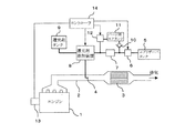
図1は、本発明のエンジンの排気浄化装置の第1実施例の構成図である。 FIG. 1 is a configuration diagram of a first embodiment of an exhaust emission control device for an engine according to the present invention.
エンジン1の排気通路である排気管2には、窒素酸化物を還元浄化する窒素酸化物還元触媒3が介装されている。
A nitrogen
窒素酸化物還元触媒3は、セラミックのコーディライトやFe−Cr−Al系の耐熱鋼からなるハニカム形状の横断面を有するモノリスタイプの触媒担体に、例えば、ゼオライト系の活性成分が担持された構成をなす。そして、触媒担体に担持された活性成分は、尿素水溶液等の液体還元剤の供給を受けて活性化し、窒素酸化物を効果的に無害物質に転化させる。
The nitrogen
窒素酸化物還元触媒3の上流には、排気管2内に開口した噴孔から液体還元剤を噴射するノズル4が設けられている。
A
エアリザーバタンク5には、700〜1000kPaに圧縮された圧縮空気が貯留されている。エアリザーバタンク5に貯留された圧縮空気は、常閉弁である電磁開閉弁6及び減圧弁7を順番に通過して、還元剤添加装置8に供給される。なお、エアリザーバタンク5は、他の用途に設けられているエアリザーバタンクと共用にしてもよい。
The
また、還元剤タンク9には、尿素水溶液等の液体還元剤が貯留されている。還元剤タンク9に貯留された液体還元剤は、還元剤添加装置8に供給される。
The reducing
還元剤添加装置8は、内部にポンプを有しており、ポンプが作動することにより圧縮空気に液体還元剤を添加し、液体還元剤を噴霧状態にした後ノズル4に供給する。なお、液体還元剤の添加流量は、ポンプの作動を制御することにより可変になっている。また、還元剤添加装置8は、供給された圧縮空気を常にノズル4に排出可能にその内部が連通している。
The reducing
エアリザーバタンク5に貯留された圧縮空気は、電磁開閉弁6を通過した後に分岐し、逆止弁10を通ってパージ用エアタンク11に供給される。このため、パージ用エアタンク11には、エアリザーバタンク5と略同圧の圧縮空気が貯留されることとなる。なお、逆止弁10は、パージ用エアタンク11から電磁開閉弁6の下流へ圧縮空気が逆流するのを阻止する。そして、パージ用エアタンク11に貯留された圧縮空気は、常閉弁である電磁開閉弁12を通過して還元剤添加装置8に供給される。
The compressed air stored in the
エンジン1には、エンジン1の回転速度や負荷を検出する運転状態検出センサ13が設けられている。マイクロコンピュータを内蔵したコントローラ14は、運転状態検出センサ13からエンジン1の回転速度や負荷を入力して、還元剤添加装置8のポンプ、電磁開閉弁6及び電磁開閉弁12を作動制御する。
The engine 1 is provided with an operation
なお、電磁開閉弁6、減圧弁7、還元剤添加装置8、還元剤タンク9、運転状態検出センサ13及びコントローラ14により還元剤噴射手段が構成される。また、パージ用エアタンク11、電磁開閉弁12及びコントローラ14により高圧空気供給手段が構成される。
Incidentally, conductive magnetic on-off
次に、このようなエンジンの排気浄化装置の動作について説明する。 Next, the operation of the engine exhaust gas purification apparatus will be described.
エンジン1が作動することにより、その排気は排気管2に排出される。このとき、コントローラ14は、運転状態検出センサ13からエンジン1の回転速度や負荷を入力し、排気中の窒素酸化物を還元するために必要な液体還元剤の噴射流量を演算する。そして、液体還元剤の噴射流量が0でないときには、電磁開閉弁6を開弁させると共に、還元剤添加装置8のポンプを液体還元剤の噴射流量に基づいて作動制御する。これにより、エアリザーバタンク5内に貯留された圧縮空気が減圧弁7により所定圧力に減圧されて還元剤添加装置8に供給され、排気中の窒素酸化物を還元するために必要な流量の液体還元剤がこの減圧された圧縮空気と混合してノズル4から排気管2内に噴射される。そして、ノズル4から噴射された液体還元剤はエンジン1からの排気と混合し窒素酸化物還元触媒3に供給され、窒素酸化物還元触媒3において排気中の窒素酸化物が還元除去される。
When the engine 1 is operated, the exhaust gas is discharged to the
また、コントローラ14は、液体還元剤の噴射流量が0となったときには、電磁開閉弁6を閉弁させると共に還元剤添加装置8のポンプの作動を停止させ、排気管2内への液体還元剤の噴射を停止させる。その後、コントローラ14は、電磁開閉弁12を所定時間開弁させる。パージ用エアタンク11に貯留された圧縮空気は、高圧空気として還元剤添加装置8に供給され、ノズル4の噴孔から排気管2内に排出される。これにより、液体還元剤の噴射が停止したときに、ノズル4の内部に液体還元剤が残留していても、圧縮空気により強制的に排気管2内に排出されるので、ノズル4の内部に液体還元剤が凝固して付着することが抑制される。このようにして、ノズル4の内部で目詰まりの発生が抑制され、液体還元剤の噴射が確保されるので、窒素酸化物還元触媒3において、還元剤が不足することなく、排気中の窒素酸化物の還元除去が効率よく行われ、排気中の窒素酸化物が大気中に放出することが抑制される。また、液体還元剤は噴霧状態でノズル4から噴射されるので、窒素酸化物還元触媒3に略均一に液体還元剤が供給され、窒素酸化物還元触媒3において排気中の窒素酸化物の還元除去が効率よく行われる。
Further, when the injection flow rate of the liquid reducing agent becomes 0, the
なお、パージ用エアタンク11に貯留された圧縮空気が使用されることにより、その圧力が低下しても、電磁開閉弁6が開弁したときにエアリザーバタンク5に貯留された圧縮空気が逆止弁10を通ってパージ用エアタンク11内に自動的に供給される。これにより、パージ用エアタンク11に貯留されている圧縮空気の圧力が所定範囲内に保持される。
In addition, even if the pressure falls by using the compressed air stored in the
次に、図2を用いて、本発明のエンジンの排気浄化装置の第2実施例を説明する。 Next, with reference to FIG. 2, illustrating a second embodiment of an exhaust purification device of an engine of the present invention.
本実施例のエンジンの排気浄化装置では、エアリザーバタンク5に貯留された圧縮空気を所定圧力に減圧させる減圧弁7に代えて、エアリザーバタンク5に貯留された圧縮空気をそのまま通過させるか又は所定圧力に減圧させて通過させるかを切換可能な減圧弁30を設け、コントローラ14により減圧弁30を切換制御するような構成にしている。
In the engine exhaust gas purification apparatus of this embodiment, instead of the pressure reducing valve 7 for reducing the compressed air stored in the
コントローラ14は、液体還元剤を噴射させるときは、電磁開閉弁6を開弁させるよう制御すると共に、圧縮空気を減圧させるように減圧弁30を切換制御する。また、コントローラ14は、液体還元剤の噴射を停止してから所定時間の間は、電磁開閉弁6を開弁させるよう制御すると共に、圧縮空気を減圧させないように減圧弁30を切換制御する。これにより、エアリザーバタンク5内の圧縮空気は、液体還元剤の噴射をするときには減圧され還元剤添加装置8に供給され、液体還元剤の噴射が停止してから所定時間の間は減圧されずに還元剤添加装置8に供給される。
When injecting the liquid reducing agent, the
このような構成により、電磁開閉弁の個数を少なくできると共に、パージ用エアタンク及び逆止弁が不要となり、簡単な構造となるので、スペースやコストを低減することができる。
なお、本実施例においては、電磁開閉弁6、還元剤添加装置8、還元剤タンク9、運転状態検出センサ13及びコントローラ14により還元剤噴射手段が構成されると共に、コントローラ14により高圧空気供給手段が、減圧弁30により減圧手段が構成される。
With such a configuration, the number of electromagnetic on-off valves can be reduced, and a purge air tank and a check valve are not required and a simple structure can be achieved, so that space and cost can be reduced.
In this embodiment, the electromagnetic on-off
1 エンジン
2 排気管
3 窒素酸化物還元触媒
4 ノズル
5 エアリザーバタンク
6 電磁開閉弁
7 減圧弁
8 還元剤添加装置
9 還元剤タンク
11 パージ用エアタンク
12 電磁開閉弁
13 運転状態検出センサ
14 コントローラ
30 減圧弁
DESCRIPTION OF SYMBOLS 1
Claims (2)
前記窒素酸化物還元触媒上流の排気通路内に噴孔が開口するノズルと、
エンジン運転状態に基づいて、前記ノズルの噴孔から排気通路内に液体還元剤を噴射する還元剤噴射手段と、
前記還元剤噴射手段による液体還元剤の噴射流量が0となったときに、前記ノズル内部に高圧空気を所定時間供給して、前記ノズル内部の液体還元剤を排出させる高圧空気供給手段と、
圧縮空気を貯留するエアリザーバタンクと、
を含んで構成され、
前記還元剤噴射手段は、前記エアリザーバタンクに貯留される圧縮空気を所定圧力に減圧し、減圧後の圧縮空気を液体還元剤と混合して噴霧状態とした後、前記ノズルの噴孔から排気通路内に噴射し、
前記高圧空気供給手段は、前記エアリザーバタンクに貯留される圧縮空気を前記高圧空気として、前記減圧後の圧縮空気よりも高い圧力で前記ノズル内部に供給することを特徴とするエンジンの排気浄化装置。 A nitrogen oxide reduction catalyst interposed in the exhaust passage of the engine to reduce and remove nitrogen oxide in the exhaust gas using a liquid reducing agent;
A nozzle injection holes open to the nitrogen oxide reduction catalyst upstream in the exhaust passage,
Reducing agent injection means for injecting a liquid reducing agent from the nozzle hole of the nozzle into the exhaust passage based on the engine operating state;
When the injection flow rate of the liquid reducing agent by the reducing agent injection means becomes 0, the high pressure air is supplied for a predetermined time to the internal nozzle, and a high pressure air supply means Ru was drained liquid reducing agent inside the nozzle,
An air reservoir tank for storing compressed air;
It is configured to include a,
The reducing agent injection means depressurizes the compressed air stored in the air reservoir tank to a predetermined pressure, mixes the compressed air after depressurization with a liquid reducing agent to form a spray state, and then exhausts the compressed air from the nozzle nozzle hole. Spray into the passage,
The high-pressure air supply means supplies compressed air stored in the air reservoir tank as the high-pressure air to the inside of the nozzle at a pressure higher than that of the compressed air after decompression. .
前記窒素酸化物還元触媒上流の排気通路内に噴孔が開口するノズルと、
エンジン運転状態に基づいて、前記ノズルの噴孔から排気通路内に液体還元剤を噴射する還元剤噴射手段と、
前記還元剤噴射手段による液体還元剤の噴射流量が0となったときに、前記ノズル内部に高圧空気を所定時間供給して、前記ノズル内部の液体還元剤を排出させる高圧空気供給手段と、
圧縮空気を貯留するエアリザーバタンクと、
前記エアリザーバタンクに貯留される圧縮空気を、そのまま通過させるか又は所定圧力に減圧させて通過させるかを切換可能な減圧手段と、
を含んで構成され、
前記還元剤噴射手段は、前記減圧手段により減圧させた圧縮空気を液体還元剤と混合して噴霧状態とした後、前記ノズルの噴孔から排気通路内に噴射し、
前記高圧空気供給手段は、前記減圧手段をそのまま通過させた圧縮空気を前記高圧空気として、前記減圧後の圧縮空気よりも高い圧力で前記ノズル内部に供給することを特徴とするエンジンの排気浄化装置。 A nitrogen oxide reduction catalyst interposed in the exhaust passage of the engine to reduce and remove nitrogen oxide in the exhaust gas using a liquid reducing agent;
A nozzle having an injection hole opened in an exhaust passage upstream of the nitrogen oxide reduction catalyst;
Reducing agent injection means for injecting a liquid reducing agent from the nozzle hole of the nozzle into the exhaust passage based on the engine operating state;
High-pressure air supply means for supplying high-pressure air into the nozzle for a predetermined time and discharging the liquid reducing agent in the nozzle when the injection flow rate of the liquid reducing agent by the reducing agent injection means becomes zero;
An air reservoir tank for storing compressed air;
The compressed air stored in the air reservoir tank, and changeover pressure reducing means or passing by vacuum as it either passes or Jo Tokoro pressure,
Comprising
The reducing agent injection hand stage, after the sprayed state compressed air so as to decrease the pressure by mixing with a liquid reducing agent by said pressure reducing means, and injected into the exhaust passage from the injection hole of said nozzle,
The high pressure air supply means, the compressed air as it passed through the pressure reducing means as said high pressure air, the pressure reducing after high pressure supply to the to Rue engine and wherein Rukoto within said nozzle than compressed air Exhaust purification device.
Priority Applications (5)
| Application Number | Priority Date | Filing Date | Title |
|---|---|---|---|
| JP2003282359A JP4152833B2 (en) | 2003-07-30 | 2003-07-30 | Engine exhaust purification system |
| CNB2004800217588A CN100432385C (en) | 2003-07-30 | 2004-07-23 | Exhaust gas purification apparatus of engine |
| US10/566,367 US7571599B2 (en) | 2003-07-30 | 2004-07-23 | Exhaust gas purification apparatus of engine |
| PCT/JP2004/010487 WO2005012702A1 (en) | 2003-07-30 | 2004-07-23 | Exhaust gas purification apparatus of engine |
| EP04747873.0A EP1655463B1 (en) | 2003-07-30 | 2004-07-23 | Exhaust gas purification apparatus of engine |
Applications Claiming Priority (1)
| Application Number | Priority Date | Filing Date | Title |
|---|---|---|---|
| JP2003282359A JP4152833B2 (en) | 2003-07-30 | 2003-07-30 | Engine exhaust purification system |
Publications (2)
| Publication Number | Publication Date |
|---|---|
| JP2005048677A JP2005048677A (en) | 2005-02-24 |
| JP4152833B2 true JP4152833B2 (en) | 2008-09-17 |
Family
ID=34113775
Family Applications (1)
| Application Number | Title | Priority Date | Filing Date |
|---|---|---|---|
| JP2003282359A Expired - Lifetime JP4152833B2 (en) | 2003-07-30 | 2003-07-30 | Engine exhaust purification system |
Country Status (5)
| Country | Link |
|---|---|
| US (1) | US7571599B2 (en) |
| EP (1) | EP1655463B1 (en) |
| JP (1) | JP4152833B2 (en) |
| CN (1) | CN100432385C (en) |
| WO (1) | WO2005012702A1 (en) |
Families Citing this family (35)
| Publication number | Priority date | Publication date | Assignee | Title |
|---|---|---|---|---|
| JP2005105970A (en) * | 2003-09-30 | 2005-04-21 | Nissan Diesel Motor Co Ltd | Exhaust emission control device of engine |
| DE102005006260A1 (en) * | 2005-02-11 | 2006-08-24 | Daimlerchrysler Ag | Addition device for adding reducing agent in an exhaust pipe of an internal combustion engine |
| JP4592504B2 (en) * | 2005-06-09 | 2010-12-01 | 三菱ふそうトラック・バス株式会社 | Exhaust purification device |
| JP4643710B2 (en) * | 2005-07-07 | 2011-03-02 | ボルボ ラストバグナー アーベー | Diagnostic method, apparatus and computer program product for at least one exhaust gas control unit |
| JP4650241B2 (en) * | 2005-11-30 | 2011-03-16 | トヨタ自動車株式会社 | Exhaust system for internal combustion engine |
| SE529591C2 (en) * | 2006-02-08 | 2007-09-25 | Stt Emtec Ab | injection device |
| JP4684150B2 (en) * | 2006-03-30 | 2011-05-18 | 三菱ふそうトラック・バス株式会社 | Air circuit control device |
| US20080034733A1 (en) * | 2006-08-14 | 2008-02-14 | Miller Robert L | Fuel supply component purging system |
| US8499739B2 (en) | 2006-08-31 | 2013-08-06 | Caterpillar Inc. | Injector having tangentially oriented purge line |
| EP2080889A4 (en) * | 2006-11-09 | 2011-02-09 | Nissan Diesel Motor Co | Ambient air temperature detector and exhaust purification apparatus |
| US8215100B2 (en) * | 2007-03-02 | 2012-07-10 | Caterpillar Inc. | Regeneration device having external check valve |
| US8006482B2 (en) * | 2007-03-02 | 2011-08-30 | Caterpillar Inc. | Method of purging fluid injector by heating |
| US7874148B2 (en) * | 2007-03-15 | 2011-01-25 | Deere & Company | Regeneration system and method for particulate traps |
| JP4174685B1 (en) * | 2007-05-31 | 2008-11-05 | 三菱自動車工業株式会社 | Exhaust gas purification device for internal combustion engine |
| US7958721B2 (en) | 2007-06-29 | 2011-06-14 | Caterpillar Inc. | Regeneration system having integral purge and ignition device |
| US8281570B2 (en) * | 2007-08-09 | 2012-10-09 | Caterpillar Inc. | Reducing agent injector having purge heater |
| ATE538288T1 (en) * | 2007-12-21 | 2012-01-15 | Renault Trucks | DEVICE FOR INJECTING A FLUID FOR AN EXHAUST GAS TREATMENT DEVICE |
| US20100154387A1 (en) * | 2008-12-19 | 2010-06-24 | Toyota Jidosha Kabushiki Kaisha | Abnormality detection device for reductant addition valve |
| DE102009014831A1 (en) * | 2009-03-25 | 2010-09-30 | Daimler Ag | A method of operating a reductant supply system |
| SE536316C2 (en) * | 2010-06-21 | 2013-08-20 | Scania Cv Ab | Method and apparatus for removing fuel from a metering unit of an HC metering system |
| SE537642C2 (en) * | 2010-06-21 | 2015-09-08 | Scania Cv Ab | Method and apparatus for cooling a reducing agent dosing unit |
| SE536318C2 (en) | 2010-06-21 | 2013-08-20 | Scania Cv Ab | Method and apparatus for removing reducing agent from a metering unit of an SCR system |
| US9145817B2 (en) * | 2010-11-08 | 2015-09-29 | Bosch Corporation | Reducing agent injection valve abnormality detection unit and reducing agent supply apparatus |
| JP5586446B2 (en) * | 2010-12-16 | 2014-09-10 | Udトラックス株式会社 | Engine exhaust pipe injector |
| JP5906637B2 (en) * | 2011-09-28 | 2016-04-20 | いすゞ自動車株式会社 | Foreign matter removal method and selective reduction catalyst system |
| JP6094974B2 (en) | 2012-02-22 | 2017-03-15 | パナソニックIpマネジメント株式会社 | Plant cultivation system |
| CN103291421B (en) | 2012-02-23 | 2016-06-08 | 天纳克(苏州)排放系统有限公司 | Air-assisted reductant metering injection system |
| WO2014143851A1 (en) * | 2013-03-15 | 2014-09-18 | Cummins Ip, Inc. | Pump purge for urea dosing system |
| JP6151980B2 (en) * | 2013-06-17 | 2017-06-21 | 株式会社荏原製作所 | Powder discharge system |
| US10473014B2 (en) * | 2013-12-23 | 2019-11-12 | Baohua Qi | Low pressure atomizing injector |
| SE540367C2 (en) * | 2014-06-12 | 2018-08-14 | Scania Cv Ab | System and method for evacuating fluid in pipelines in a vehicle |
| US11585253B2 (en) | 2015-08-07 | 2023-02-21 | Cummins Emission Solutions Inc. | Converging liquid reductant injector nozzle in selective catalytic reduction systems |
| KR102466782B1 (en) * | 2016-05-27 | 2022-11-16 | 에이치에스디엔진 주식회사 | Reductant supply system |
| CN108479347B (en) * | 2018-04-13 | 2020-05-05 | 宁波清智环保科技有限公司 | Environment-friendly gas purification device |
| DE112019007644T5 (en) * | 2019-08-22 | 2022-05-19 | Cummins Emission Solutions Inc. | Systems and methods for generating ammonia |
Family Cites Families (18)
| Publication number | Priority date | Publication date | Assignee | Title |
|---|---|---|---|---|
| JPH0615815B2 (en) * | 1987-06-22 | 1994-03-02 | 三菱自動車工業株式会社 | Regeneration device by burner of diesel particulate trap |
| KR950012137B1 (en) * | 1989-02-02 | 1995-10-14 | 닛뽄 쇼크바이 카가꾸 고오교오 가부시기가이샤 | Method of removing nitrogen oxides in exhaust gases from a diesel engine |
| CA2088713C (en) | 1992-02-24 | 1999-11-16 | Hans Thomas Hug | Cleaning exhaust gases from combustion installations |
| DK0617199T3 (en) * | 1993-03-26 | 1996-07-01 | Siemens Ag | Catalyst for nitric oxide reduction in the exhaust gas from an internal combustion engine |
| JP2937738B2 (en) | 1994-04-05 | 1999-08-23 | 株式会社新潟鉄工所 | Reducing agent spraying equipment for flue gas denitration equipment |
| EP0839264B1 (en) * | 1994-09-13 | 1999-12-01 | Siemens Aktiengesellschaft | Process and device for introducing a fluid into an exhaust gas purification system |
| DE4436397B4 (en) * | 1994-10-12 | 2006-06-08 | Robert Bosch Gmbh | Device for aftertreatment of exhaust gases |
| DE19531028A1 (en) * | 1995-08-23 | 1997-02-27 | Siemens Ag | Process for exhaust gas purification and exhaust gas purification device for an internal combustion engine |
| DE19726392A1 (en) * | 1997-06-21 | 1998-12-24 | Bosch Gmbh Robert | Mixture dispenser |
| DE19738859A1 (en) * | 1997-09-05 | 1999-03-11 | Bosch Gmbh Robert | Mixture dispenser |
| JP3565035B2 (en) * | 1998-07-10 | 2004-09-15 | 三菱ふそうトラック・バス株式会社 | NOx reduction system for combustion exhaust gas |
| JP2000027627A (en) | 1998-07-13 | 2000-01-25 | Hino Motors Ltd | Reducing agent thermal insulating device for exhaust gas cleaning catalyst, and exhaust emission control device provided with this thermal insulating device |
| JP2000257419A (en) * | 1999-03-03 | 2000-09-19 | Toyota Motor Corp | Exhaust purification method and device thereof |
| US6167698B1 (en) * | 1999-12-21 | 2001-01-02 | Ford Motor Company | Exhaust gas purification system for a lean burn engine |
| JP3613676B2 (en) * | 2000-07-24 | 2005-01-26 | トヨタ自動車株式会社 | Exhaust gas purification device for internal combustion engine |
| DE10047516A1 (en) * | 2000-09-22 | 2002-04-18 | Bosch Gmbh Robert | Method and device for dosing a reducing agent for removing nitrogen oxides from exhaust gases |
| JP3545691B2 (en) * | 2000-09-27 | 2004-07-21 | 日野自動車株式会社 | Operating method of exhaust gas purification device |
| JP4131783B2 (en) * | 2001-05-09 | 2008-08-13 | 日産ディーゼル工業株式会社 | Exhaust gas purification device for internal combustion engine |
-
2003
- 2003-07-30 JP JP2003282359A patent/JP4152833B2/en not_active Expired - Lifetime
-
2004
- 2004-07-23 WO PCT/JP2004/010487 patent/WO2005012702A1/en active Application Filing
- 2004-07-23 US US10/566,367 patent/US7571599B2/en active Active
- 2004-07-23 CN CNB2004800217588A patent/CN100432385C/en active Active
- 2004-07-23 EP EP04747873.0A patent/EP1655463B1/en active Active
Also Published As
| Publication number | Publication date |
|---|---|
| CN1839252A (en) | 2006-09-27 |
| EP1655463A1 (en) | 2006-05-10 |
| US7571599B2 (en) | 2009-08-11 |
| JP2005048677A (en) | 2005-02-24 |
| EP1655463A4 (en) | 2009-12-23 |
| EP1655463B1 (en) | 2016-07-06 |
| WO2005012702A1 (en) | 2005-02-10 |
| US20070186542A1 (en) | 2007-08-16 |
| CN100432385C (en) | 2008-11-12 |
Similar Documents
| Publication | Publication Date | Title |
|---|---|---|
| JP4152833B2 (en) | Engine exhaust purification system | |
| JP6016627B2 (en) | Exhaust purification device | |
| US9597637B2 (en) | Exhaust gas post-processing apparatus and control method thereof | |
| US7251929B2 (en) | Thermal management of hybrid LNT/SCR aftertreatment during desulfation | |
| KR102617164B1 (en) | Method for the operation of an exhaust gas aftertreatment system | |
| JP3732493B2 (en) | Engine exhaust purification system | |
| WO2006025110A1 (en) | Exhaust gas purifier | |
| JP2007198316A (en) | Device and method for controlling exhaust gas of internal combustion engine | |
| JP2009002260A (en) | Exhaust emission control device | |
| JP2004270609A (en) | Emission control device | |
| JP6058878B2 (en) | Exhaust gas purification device | |
| WO2005085607A1 (en) | Exhaust emission control device of engine | |
| KR101525302B1 (en) | Selective catalytic reuction system and method of regenerating catalyst for selective catalytic reuction | |
| KR101842296B1 (en) | Selective Catalyst Reduction system with purging line | |
| JP2018145869A (en) | Exhaust emission control system and sulfur poisoning restriction method for exhaust emission control system | |
| JP5778951B2 (en) | Exhaust gas purification device | |
| CN101614147B (en) | Exhaust purification apparatus of internal-combustion engine | |
| US10132223B2 (en) | Exhaust purifier | |
| WO2006061943A1 (en) | Exhaust gas purification apparatus | |
| US20110239633A1 (en) | Exhaust emission purifying apparatus | |
| JPH10212931A (en) | Exhaust gas emission control device for internal combustion engine | |
| JP2007239618A (en) | Exhaust emission control device of diesel engine | |
| JP2018100600A (en) | Exhaust emission control system and poisoning control method for exhaust emission control system | |
| JP2016098710A (en) | Urea water recovery system of internal combustion engine, internal combustion engine, and urea water recovery method of internal combustion engine | |
| JP2016098714A (en) | Urea water injection system of internal combustion engine, internal combustion engine, and urea water injection method of internal combustion engine |
Legal Events
| Date | Code | Title | Description |
|---|---|---|---|
| A621 | Written request for application examination |
Free format text: JAPANESE INTERMEDIATE CODE: A621 Effective date: 20060330 |
|
| A131 | Notification of reasons for refusal |
Free format text: JAPANESE INTERMEDIATE CODE: A131 Effective date: 20080226 |
|
| A521 | Request for written amendment filed |
Free format text: JAPANESE INTERMEDIATE CODE: A523 Effective date: 20080425 |
|
| TRDD | Decision of grant or rejection written | ||
| A01 | Written decision to grant a patent or to grant a registration (utility model) |
Free format text: JAPANESE INTERMEDIATE CODE: A01 Effective date: 20080701 |
|
| A01 | Written decision to grant a patent or to grant a registration (utility model) |
Free format text: JAPANESE INTERMEDIATE CODE: A01 |
|
| A61 | First payment of annual fees (during grant procedure) |
Free format text: JAPANESE INTERMEDIATE CODE: A61 Effective date: 20080702 |
|
| R150 | Certificate of patent or registration of utility model |
Ref document number: 4152833 Country of ref document: JP Free format text: JAPANESE INTERMEDIATE CODE: R150 Free format text: JAPANESE INTERMEDIATE CODE: R150 |
|
| FPAY | Renewal fee payment (event date is renewal date of database) |
Free format text: PAYMENT UNTIL: 20110711 Year of fee payment: 3 |
|
| FPAY | Renewal fee payment (event date is renewal date of database) |
Free format text: PAYMENT UNTIL: 20110711 Year of fee payment: 3 |
|
| S533 | Written request for registration of change of name |
Free format text: JAPANESE INTERMEDIATE CODE: R313533 |
|
| FPAY | Renewal fee payment (event date is renewal date of database) |
Free format text: PAYMENT UNTIL: 20110711 Year of fee payment: 3 |
|
| R350 | Written notification of registration of transfer |
Free format text: JAPANESE INTERMEDIATE CODE: R350 |
|
| FPAY | Renewal fee payment (event date is renewal date of database) |
Free format text: PAYMENT UNTIL: 20110711 Year of fee payment: 3 |
|
| FPAY | Renewal fee payment (event date is renewal date of database) |
Free format text: PAYMENT UNTIL: 20140711 Year of fee payment: 6 |
|
| R250 | Receipt of annual fees |
Free format text: JAPANESE INTERMEDIATE CODE: R250 |
|
| R250 | Receipt of annual fees |
Free format text: JAPANESE INTERMEDIATE CODE: R250 |
|
| R250 | Receipt of annual fees |
Free format text: JAPANESE INTERMEDIATE CODE: R250 |
|
| R250 | Receipt of annual fees |
Free format text: JAPANESE INTERMEDIATE CODE: R250 |
|
| R250 | Receipt of annual fees |
Free format text: JAPANESE INTERMEDIATE CODE: R250 |
|
| R250 | Receipt of annual fees |
Free format text: JAPANESE INTERMEDIATE CODE: R250 |
|
| R250 | Receipt of annual fees |
Free format text: JAPANESE INTERMEDIATE CODE: R250 |
|
| R250 | Receipt of annual fees |
Free format text: JAPANESE INTERMEDIATE CODE: R250 |
|
| S111 | Request for change of ownership or part of ownership |
Free format text: JAPANESE INTERMEDIATE CODE: R313113 |
|
| S533 | Written request for registration of change of name |
Free format text: JAPANESE INTERMEDIATE CODE: R313533 |
|
| R360 | Written notification for declining of transfer of rights |
Free format text: JAPANESE INTERMEDIATE CODE: R360 |
|
| R360 | Written notification for declining of transfer of rights |
Free format text: JAPANESE INTERMEDIATE CODE: R360 |
|
| R371 | Transfer withdrawn |
Free format text: JAPANESE INTERMEDIATE CODE: R371 |
|
| R360 | Written notification for declining of transfer of rights |
Free format text: JAPANESE INTERMEDIATE CODE: R360 |
|
| S111 | Request for change of ownership or part of ownership |
Free format text: JAPANESE INTERMEDIATE CODE: R313113 |
|
| R360 | Written notification for declining of transfer of rights |
Free format text: JAPANESE INTERMEDIATE CODE: R360 |
|
| R371 | Transfer withdrawn |
Free format text: JAPANESE INTERMEDIATE CODE: R371 |
|
| R250 | Receipt of annual fees |
Free format text: JAPANESE INTERMEDIATE CODE: R250 |
|
| R360 | Written notification for declining of transfer of rights |
Free format text: JAPANESE INTERMEDIATE CODE: R360 |
|
| R360 | Written notification for declining of transfer of rights |
Free format text: JAPANESE INTERMEDIATE CODE: R360 |
|
| R371 | Transfer withdrawn |
Free format text: JAPANESE INTERMEDIATE CODE: R371 |
|
| R250 | Receipt of annual fees |
Free format text: JAPANESE INTERMEDIATE CODE: R250 |
|
| EXPY | Cancellation because of completion of term |