EP1110590A2 - Flüssigkeitsfilter mit Ablass für Flüssigkeitsrückstände - Google Patents
Flüssigkeitsfilter mit Ablass für Flüssigkeitsrückstände Download PDFInfo
- Publication number
- EP1110590A2 EP1110590A2 EP00121914A EP00121914A EP1110590A2 EP 1110590 A2 EP1110590 A2 EP 1110590A2 EP 00121914 A EP00121914 A EP 00121914A EP 00121914 A EP00121914 A EP 00121914A EP 1110590 A2 EP1110590 A2 EP 1110590A2
- Authority
- EP
- European Patent Office
- Prior art keywords
- housing
- liquid
- screw cap
- outlet
- opening
- Prior art date
- Legal status (The legal status is an assumption and is not a legal conclusion. Google has not performed a legal analysis and makes no representation as to the accuracy of the status listed.)
- Granted
Links
- 239000007788 liquid Substances 0.000 title claims abstract description 47
- 238000009434 installation Methods 0.000 claims description 17
- 238000002485 combustion reaction Methods 0.000 claims description 7
- 239000010687 lubricating oil Substances 0.000 claims description 6
- 238000007789 sealing Methods 0.000 claims description 4
- 238000006073 displacement reaction Methods 0.000 claims description 2
- 239000003921 oil Substances 0.000 description 8
- 230000008859 change Effects 0.000 description 5
- 230000008901 benefit Effects 0.000 description 4
- 238000009795 derivation Methods 0.000 description 3
- 230000002349 favourable effect Effects 0.000 description 2
- 239000000463 material Substances 0.000 description 2
- 230000009471 action Effects 0.000 description 1
- 230000009286 beneficial effect Effects 0.000 description 1
- 238000010276 construction Methods 0.000 description 1
- 238000011161 development Methods 0.000 description 1
- 230000018109 developmental process Effects 0.000 description 1
- 239000012530 fluid Substances 0.000 description 1
- 230000010354 integration Effects 0.000 description 1
- 230000007246 mechanism Effects 0.000 description 1
Images

Classifications
-
- B—PERFORMING OPERATIONS; TRANSPORTING
- B01—PHYSICAL OR CHEMICAL PROCESSES OR APPARATUS IN GENERAL
- B01D—SEPARATION
- B01D29/00—Filters with filtering elements stationary during filtration, e.g. pressure or suction filters, not covered by groups B01D24/00 - B01D27/00; Filtering elements therefor
- B01D29/11—Filters with filtering elements stationary during filtration, e.g. pressure or suction filters, not covered by groups B01D24/00 - B01D27/00; Filtering elements therefor with bag, cage, hose, tube, sleeve or like filtering elements
- B01D29/13—Supported filter elements
- B01D29/15—Supported filter elements arranged for inward flow filtration
- B01D29/21—Supported filter elements arranged for inward flow filtration with corrugated, folded or wound sheets
-
- B—PERFORMING OPERATIONS; TRANSPORTING
- B01—PHYSICAL OR CHEMICAL PROCESSES OR APPARATUS IN GENERAL
- B01D—SEPARATION
- B01D29/00—Filters with filtering elements stationary during filtration, e.g. pressure or suction filters, not covered by groups B01D24/00 - B01D27/00; Filtering elements therefor
- B01D29/96—Filters with filtering elements stationary during filtration, e.g. pressure or suction filters, not covered by groups B01D24/00 - B01D27/00; Filtering elements therefor in which the filtering elements are moved between filtering operations; Particular measures for removing or replacing the filtering elements; Transport systems for filters
-
- B—PERFORMING OPERATIONS; TRANSPORTING
- B01—PHYSICAL OR CHEMICAL PROCESSES OR APPARATUS IN GENERAL
- B01D—SEPARATION
- B01D35/00—Filtering devices having features not specifically covered by groups B01D24/00 - B01D33/00, or for applications not specifically covered by groups B01D24/00 - B01D33/00; Auxiliary devices for filtration; Filter housing constructions
- B01D35/14—Safety devices specially adapted for filtration; Devices for indicating clogging
- B01D35/147—Bypass or safety valves
-
- B—PERFORMING OPERATIONS; TRANSPORTING
- B01—PHYSICAL OR CHEMICAL PROCESSES OR APPARATUS IN GENERAL
- B01D—SEPARATION
- B01D35/00—Filtering devices having features not specifically covered by groups B01D24/00 - B01D33/00, or for applications not specifically covered by groups B01D24/00 - B01D33/00; Auxiliary devices for filtration; Filter housing constructions
- B01D35/14—Safety devices specially adapted for filtration; Devices for indicating clogging
- B01D35/153—Anti-leakage or anti-return valves
-
- B—PERFORMING OPERATIONS; TRANSPORTING
- B01—PHYSICAL OR CHEMICAL PROCESSES OR APPARATUS IN GENERAL
- B01D—SEPARATION
- B01D35/00—Filtering devices having features not specifically covered by groups B01D24/00 - B01D33/00, or for applications not specifically covered by groups B01D24/00 - B01D33/00; Auxiliary devices for filtration; Filter housing constructions
- B01D35/16—Cleaning-out devices, e.g. for removing the cake from the filter casing or for evacuating the last remnants of liquid
-
- B—PERFORMING OPERATIONS; TRANSPORTING
- B01—PHYSICAL OR CHEMICAL PROCESSES OR APPARATUS IN GENERAL
- B01D—SEPARATION
- B01D2201/00—Details relating to filtering apparatus
- B01D2201/16—Valves
- B01D2201/162—Valves with snap, latch or clip connecting means
-
- B—PERFORMING OPERATIONS; TRANSPORTING
- B01—PHYSICAL OR CHEMICAL PROCESSES OR APPARATUS IN GENERAL
- B01D—SEPARATION
- B01D2201/00—Details relating to filtering apparatus
- B01D2201/30—Filter housing constructions
- B01D2201/301—Details of removable closures, lids, caps, filter heads
- B01D2201/305—Snap, latch or clip connecting means
-
- B—PERFORMING OPERATIONS; TRANSPORTING
- B01—PHYSICAL OR CHEMICAL PROCESSES OR APPARATUS IN GENERAL
- B01D—SEPARATION
- B01D2201/00—Details relating to filtering apparatus
- B01D2201/40—Special measures for connecting different parts of the filter
- B01D2201/4084—Snap or Seeger ring connecting means
Definitions
- the invention relates to a liquid filter, in particular for the lubricating oil Internal combustion engine, which has a cup-shaped housing with a screw cap, a drain for liquid residues is housed in the screw cap, after the type of claim 1.
- the invention also relates to a filter cartridge, which is suitable for installation in the liquid filter, according to the preamble of the claim 10th
- Such a liquid filter is e.g. B. known from DE 196 44 647 A1.
- This Filter has a cup-shaped housing, the installation opening for the filter cartridge after below and screwed into the screw cap after installing the filter cartridge can be.
- Inlet and outlet for the filter are in the housing pot, d. H. in the upper part of the filter housing.
- This makes it difficult to change the filter cartridge, as this Residual liquid can get into the environment when the cover is screwed on. Because of that is a drain plug in the screw cap at its geodetically lowest point provided, which can first be solved to the liquid residue in the Remove screw cap. This makes changing the filter cartridge essential facilitated.
- the proposed liquid filter is used in particular as an oil filter Internal combustion engines used.
- the space conditions due to others Components in the engine compartment are often very cramped. That is why an actuation of the Drain plug often associated with problems. It must also come out of the drain opening leaking oil can be caught. This is also due to the cramped Installation situation is often only possible under difficult conditions. There a Collection container with sufficient volume is not placed under the drain opening can be.
- the object of the invention is therefore a liquid filter with a liquid drain in the screw cap, which can also be used in tight spaces can be reliably emptied.
- This object is achieved by the features of the claim 1 and the features of claim 3 solved.
- a filter cartridge according to claim 10 which when installed in a Liquid filter is able to solve the task.
- the liquid filter according to the invention is intended for installation in a hanging position.
- the housing axis does not have to be vertical, it is also possible to mount the housing to be aligned so that the central axis of the housing points obliquely downwards.
- the Housing pot need not be a separate component. It is also conceivable that this by another component, e.g. B. the engine block is formed.
- a drain for liquid residues is provided in the screw cap, which according to the invention has a connection for a discharge device, the purpose the drain is installed and again after the drainage of the liquid residues can be dismantled.
- This has the advantage that in the direct area of the drain only space for the connection of the discharge device must be available. This can be connected to the drain, after which the drain is opened becomes.
- the discharge device conveys the liquid to a designated one Collecting container. As soon as all liquid residues are removed from the housing are, the derivation device can be dismantled so that it opens the opening of the Screw cap no longer hindered.
- the derivation device exists from a hose, which on a corresponding hose connector on Screw cap is attachable.
- This variant represents a particularly simple option represents to realize the derivation device. So this does not result in an increased Component effort, which is beneficial to the economy of the solution.
- Corresponding drainage hoses are easy to procure and in the service provider Workshop available.
- valve rod that the drain opening via a seal closes.
- the seal can e.g. B. be an O-ring, but it is also possible that the valve rod due to a corresponding choice of material as such sealing functions takes over.
- the valve rod is connected to the housing pot in such a way that whose axial play is limited with respect to the central axis of the housing. Below is also the possibility to understand no axial play for the valve rod at all to provide.
- This can e.g. B. screwed or locked with the housing pot. If the screw cap in which the round drain opening is located is loosened, so this moves relative to the valve rod limited axial movement is. This pulls the valve stem seal out of the drain hole and this automatically released to the liquid residues. As soon as the liquid has drained off, the screw cap can be completely removed from the housing pot be unscrewed in order to then change the filter cartridge.
- the advantage of this solution according to the invention is that the drain opening is automatic is opened by partially unscrewing the screw cap. Therefore the drain opening must not be closed for special tools, e.g. B. one Wrench, be accessible. Because the action space of an opening tool for the drain opening does not have to be considered, the invention can Liquid filters can also be installed in tight spaces. Hereby there is a greater geometric freedom of design of the internal combustion engine.
- a favorable embodiment of the invention results when the valve rod is on a support tube is mounted, which in turn is fixed in the housing pot.
- a support tube must be used in most applications be provided to the filter cartridge against that present on the filter medium To support pressure differences. If the valve rod is attached directly to the support tube, it can be made shorter than when it is fastened in the housing pot. Therefore The stability of the valve rod increases and material is saved. this leads to ultimately also to increase the profitability of the solution.
- a particularly favorable embodiment of the invention results when the support tube releasably connected to both the housing pot and the screw cap is.
- an axial play must be provided when connecting to the screw cap be, which ends by screwing on the cover at an axial stop.
- the fastening in the screw cap may only in the axial direction and not in radial direction so that the cover can be screwed on.
- the axial play area, that is formed by the stops in the screw cap must be smaller be than the axial movement of the opening required to open the drain opening Screw cap. This ensures that the support tube when opening the screw cap initially remains in the housing pot, so that the valve rod in the already described Pulled out of the drain opening in the screw cap. Now the liquid residue can run out of the screw cap.
- the support tube reaches the axial stop in the screw cap, whereby the loosening of this axial stop requires a greater loosening force than the clamping the support tube in the housing pot. Therefore, the support tube remains during disassembly of the liquid filter in the screw cap. With an appropriate attachment the filter cartridge remains on the support tube and can therefore also be put together be removed from the housing pot with the screw cap.
- the filter cartridge With an appropriate attachment the filter cartridge remains on the support tube and can therefore also be put together be removed from the housing pot with the screw cap.
- the hose connector for attaching the drain hose can pass through the drain opening be formed in the screw cap itself.
- This hose connector points outwards so that a hose is attached before screwing on the screw cap can be. Due to its flexibility, it is possible to use some screw caps Turns so that the drain opening opens automatically.
- valve stem with a tubular one End to be provided.
- the openings are in the installed state of the filter cartridge covered by a bushing in the screw cap. By unscrewing the lid the breakthroughs migrate into the interior of the screw cap, causing the Residual liquid can get through the openings in the outlet end. To this It is possible to discharge the residual liquid.
- outlet end is advantageous to design the outlet end as a hose connector.
- the outlet hose can be attached in the manner already described. This has the additional advantage that the valve stem when screwing the Screw cap does not turn. This simplifies handling when changing the filter, because the hose is attached to an accessible Can be performed and remains there during the screwing movement.
- a can in the support tube Bypass valve are provided. Is the support tube with an axial stop connected to the screw cap, however, this connection must be permeable to liquids be designed to allow access to the bypass valve. Otherwise the immediate liquid could not be in the formed by the support tube Get inside, making the filter bypass possible.
- the filter cartridge required for the described filter change can be made according to the invention be fitted with a support tube for installation in this liquid filter, in which the valve stem is integrated.
- the support tube can be detachable or non-detachable be connected to the filter cartridge.
- a seal between the filter cartridge and Support tube can be made directly through the end plates of the filter cartridge.
- the support tube can also be cast in at least one of the end plates, whereby an inseparable connection is created. In this case the support tube is always together replaced with the filter element.
- the filter shown in Figure 1 consists of a housing 10, which a Includes screw cap 11 which is screwed into a housing pot 12.
- the Housing pot is designed as part of an engine block, not shown. about this engine block are also an inlet 13 and an outlet 14 for that to be filtered Lubricating oil of the internal combustion engine realized.
- the housing pot has a downward-facing installation opening 15, which the Installation of a filter cartridge 16 permitted. This is for mounting on a nozzle 17th pushed, creating a seal between a raw side 18 and a clean side 19 of the filter medium 20 is reached. Sealing takes place via the elastic executed upper end plate 21a.
- the lower end plate 21b is over a support tube 22 sealed, which after mounting the filter cartridge 16 on the nozzle 17 can be inserted into the clean side 19 of the filter cartridge, one Snap connection 23 engages between support tube 22 and connecting piece 17. Subsequently the screw cap can be screwed on from below, whereby a Axial fixation 24 provided with an axial play area a is closed.
- the axial play area a results from correspondingly spaced lugs 25, on the one hand are housed in the screw cap and on the other hand in the support tube.
- the screw cap is sealed against the housing pot using a molded seal 26.
- a drain opening 27 of a drain 28 in the bottom of the screw cap 11 be sealed.
- the support tube 22 is provided with a valve rod 29 provided, the end of which extends into the drain opening 27 and this via a Seal 30 closes.
- the direction of flow of the lubricating oil to be cleaned through the filter during normal Operating is indicated by arrows.
- the filter cartridge 16 is from the outside Flows through inside, whereby a fluid flow from the inlet 13 to the outlet 14 is possible becomes.
- a bypass valve 31 is arranged in the support tube 22, which in the event of an inadmissible increase in the differential pressure between clean side 19 and Raw side 18 opens, thereby supplying the internal combustion engine with lubricating oil is guaranteed.
- the screw cap 11 When changing the filter cartridge 16, the screw cap 11 is initially a few Loosened rotations from the housing pot 12. This creates an axial displacement the screw cap, which must be smaller than the axial play area a. A thread 32 between the screw cap 11 and the housing pot 12 must be longer than the axial play area a. Therefore remains after the first turns of the screw cap this is still connected to the housing pot.
- the support tube 22 Through the snap connection 23, the support tube 22 is still fixed in the housing pot 12. Since the drain opening 27 arranged exactly in a central axis 33 of the housing 10, is between the valve rod 29 and the screw cap 11 containing the drain opening 27 are both one axial as well as radial relative movement possible.
- the valve rod 29 By unscrewing the lid the valve rod 29 is therefore pulled out of the drain opening 27, whereby the residual oil in the screw cap can drain off.
- the drain opening 27 with a Provide hose connector 34a. This can be used before opening the drain Hose 35 are plugged into a provided, not shown Collection vessel can be passed.
- the screw cap 11 When the residual oil has run out of the housing, the screw cap 11 be unscrewed further.
- the lugs 25 of the axial fixation form one Stop, the loosening force of this axial fixation is greater than that of the snap connection 23. Therefore, when unscrewing the screw cap again, the Snap connection 23 released so that the support tube remains in the screw cap. If the end plate 21b has a greater loosening force on the support tube than on the socket 17, this also remains in the screw cap 11. This makes it unproblematic Reach the filter cartridge.
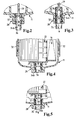
- FIGs 2 and 3 represent an alternative embodiment of the drain 28 Hose connector 34b is in this case part of the valve rod 29, which thereby End 36 forms.
- the outlet end thus replaces the outlet opening 27 according to Figure 1.
- the opening in the screw cap 11 thus serves only as a passage 37 for the outlet end 36.
- To connect the outlet end 36 with the interior of the Openings 38 are provided in the tubular outlet end. While the operation of the filter ( Figure 2) these breakthroughs through the seals 30 sealed, which prevents oil from leaking.
- the mechanism shown in Figure 1 is by screwing on the screw cap a relative movement between valve rod 29 and bushing 37 is achieved, whereby the breakthroughs 38 are exposed. This allows the oil to flow out and drain the hose 35 plugged onto the hose connector 34b (in FIG 3 and 5 indicated by an arrow).
- FIG. 4 and 5 show a further embodiment with an outlet end. This is similar to the embodiment shown in Figure 2, what is identified by the same reference numerals. The difference is that the valve rod 29 is firmly integrated with the support tube 22 in the filter cartridge 16 is.
- the embodiment according to FIG. 2 is based on the embodiment according to Figure 1, the valve rod 29 part of a removable center tube is. It follows from this that the support tube according to FIG. 4 is not together with the cover, but is removed together with the cartridge. This explains the other dimensions of the screw cap 11, the thread 32 in the lower region the filter cartridge 16 is located. This embodiment is particularly simple in construction and therefore cheaper. However, in the area below the installation opening 25 requires a larger expansion area for the filter cartridge 16.
Landscapes
- Chemical & Material Sciences (AREA)
- Chemical Kinetics & Catalysis (AREA)
- Lubrication Details And Ventilation Of Internal Combustion Engines (AREA)
- Filtration Of Liquid (AREA)
Abstract
Description
- Figur 1
- den Längsschnitt durch den erfindungsgemäßen Filter mit einer an das Stützrohr angebrachten Ventilstange und Schlauchanschluß,
- Figur 2
- eine andere Variante des Details X gem. Figur 1, wobei der Schlauchstutzen in die Ventilstange integriert ist,
- Figur 3
- die Ventilstange gem. Figur 2 im geöffneten Zustand,
- Figur 4
- den Ausschnitt eines Filterelementes, bei dem das Stützrohr mit der Ventilstange in die Filterpatrone integriert ist in eingebautem Zustand, wobei das Filtergehäuse geschnitten dargestellt ist und
- Figur 5
- die Ventilstange gemäß Figur 4 mit aufgestecktem Schlauch und im geöffneten Zustand.
Claims (10)
- Flüssigkeitsfilter, insbesondere für das Schmieröl eine Brennkraftmaschine, welches ein Gehäuse (10) mit einem Einlaß (13) und einem Auslaß (14) für die zu filternde Flüssigkeit, bestehend aus einem mit einer Einbauöffnung (15) nach unten weisenden Gehäusetopf (12) und einem die Einbauöffnung verschließenden Schraubdeckel (11), aufweist, wobei in das Gehäuse eine Filterpatrone (16) den Einlaß (13) von dem Auslaß (14) dichtend voneinander trennend eingebaut ist und wobei der Schraubdeckel einen Ablaß (28) für Flüssigkeitsrückstände im Gehäuse aufweist, dadurch gekennzeichnet, dass der Ablaß (28) mit einem Anschluß für eine Ableitungseinrichtung versehen ist, wobei die Ableitungseinrichtung demontierbar ist.
- Flüssigkeitsfilter nach Anspruch 1, dadurch gekennzeichnet, dass der Anschluß ein Schlauchstutzen (34a,b) und die Ableitungseinrichtung ein Schlauch (35) ist, der auf den Schlauchstutzen (34a,b) aufsteckbar ist.
- Flüssigkeitsfilter, insbesondere für das Schmieröl eine Brennkraftmaschine, welches ein Gehäuse (10) mit einem Einlaß (13) und einem Auslaß (14) für die zu filternde Flüssigkeit, bestehend aus einem mit einer Einbauöffnung (15) nach unten weisenden Gehäusetopf (12) und einem die Einbauöffnung verschließenden Schraubdeckel (11), aufweist, wobei in das Gehäuse eine Filterpatrone (16) den Einlaß (13) von dem Auslaß (14) dichtend voneinander trennend eingebaut ist und wobei der Schraubdeckel einen Ablaß (28) für Flüssigkeitsrückstände im Gehäuse aufweist, dadurch gekennzeichnet, dass der Ablaß eine Ventilstange (29) aufweist,deren Axialspiel im Bezug auf eine Mittelachse (33) des Gehäuses dadurch begrenzt ist, daß diese mit dem Gehäusetopf (12) verbunden ist,die eine in der Mittelachse (33) angeordnete, runde Ablauföffnung (27) dichtend verschließt unddie in der Ablauföffnung (27) axial beweglich ist, wobei eine Dichtung (30) zwischen Ventilstange (29) und Ablauföffnung (27) vorgesehen ist.
- Flüssigkeitsfilter nach Anspruch 3, dadurch gekennzeichnet, dass die Ventilstange mit einem Stützrohr (22) verbunden ist, welches seinerseits im Gehäusetopf (12) befestigt ist.
- Flüssigkeitsfilter nach Anspruch 4, dadurch gekennzeichnet, dass das Stützrohr (22) lösbar mit dem Gehäusetopf (12) verbunden ist und zusätzlich eine Axialfixierung (24) mit einem Axialspielbereich a zum Schraubdeckel (11) aufweist, wobeider Axialspielbereich a in Öffnungsrichtung des Schraubdeckels (11) einen Anschlag aufweist,der Axialspielbereich a größer ist als der zur Öffnung der Ablauföffnung (27) notwendige axiale Verschiebeweg der Ventilstange (29)der Anschlag eine lösbare Verbindung zwischen Stützrohr (22) und Schraubdeckel (11) darstellt, wobei die nötige Zugkraft zur Lösung dieser Verbindung größer ist, als die Zugkraft zur Lösung der Verbindung zwischen Stützrohr und Gehäusetopf (12).
- Flüssigkeitsfilter nach einem der Ansprüche 3 bis 5, dadurch gekennzeichnet, dass die Ablauföffnung (27) durch einen nach außen zeigenden Schlauchstutzen (34a) am Schraubdeckel (11) gebildet ist.
- Flüssigkeitsfilter nach einem der Ansprüche 3 bis 5, dadurch gekennzeichnet, dass die Ablauföffnung (27) durch ein rohrförmiges Auslaufende (36) der Ventilstange gebildet ist, wobei das Auslaufende in eine Durchführung (37) im Schraubdeckel hineinragt und die Rohrwand des Auslaufendes mit Durchbrüchen (38) versehen ist. Flüssigkeitsfilter nach Anspruch 7, dadurch gekennzeichnet, dass das Auslaufende (36) als Schlauchstutzen ausgeführt ist.
- Flüssigkeitsfilter nach einem der vorherigen Ansprüche, dadurch gekennzeichnet, dass ein Umgehungsventil (31) im Stützrohr (22) angeordnet ist.
- Filterpatrone zum Einbau in einen Flüssigkeitsfilter nach einem der vorhergehenden Ansprüche, dadurch gekennzeichnet, dass in diese das Stützrohr (22) eingebracht ist.
- Filterpatrone zum Einbau in einen Flüssigkeitsfilter nach einem der vorhergehenden Ansprüche, dadurch gekennzeichnet, dass in diese das Stützrohr (22) eingebracht ist.
Applications Claiming Priority (2)
| Application Number | Priority Date | Filing Date | Title |
|---|---|---|---|
| DE19961580A DE19961580A1 (de) | 1999-12-21 | 1999-12-21 | Flüssigkeitsfilter mit Ablaß für Flüssigkeitsrückstände |
| DE19961580 | 1999-12-21 |
Publications (3)
| Publication Number | Publication Date |
|---|---|
| EP1110590A2 true EP1110590A2 (de) | 2001-06-27 |
| EP1110590A3 EP1110590A3 (de) | 2004-04-28 |
| EP1110590B1 EP1110590B1 (de) | 2014-04-02 |
Family
ID=7933500
Family Applications (1)
| Application Number | Title | Priority Date | Filing Date |
|---|---|---|---|
| EP00121914.6A Expired - Lifetime EP1110590B1 (de) | 1999-12-21 | 2000-10-07 | Flüssigkeitsfilter mit Ablass für Flüssigkeitsrückstände |
Country Status (4)
| Country | Link |
|---|---|
| US (1) | US6485637B2 (de) |
| EP (1) | EP1110590B1 (de) |
| JP (1) | JP4473443B2 (de) |
| DE (1) | DE19961580A1 (de) |
Cited By (12)
| Publication number | Priority date | Publication date | Assignee | Title |
|---|---|---|---|---|
| WO2008025022A2 (en) * | 2006-08-25 | 2008-02-28 | Honeywell International Inc. | Filter and method of sericing |
| WO2008134494A3 (en) * | 2007-04-27 | 2009-04-16 | Donaldson Co Inc | Liquid filter assembly, system, and methods |
| EP2072768A1 (de) * | 2007-12-20 | 2009-06-24 | Mann+Hummel Gmbh | Ölfilter eines Verbrennungsmotors und Filterpatrone für den Ölfilter |
| WO2009132291A2 (en) * | 2008-04-25 | 2009-10-29 | Donaldson Company, Inc. | Top load liquid filter assembly, system, and methods |
| EP2808071A1 (de) * | 2013-05-29 | 2014-12-03 | Mahle International GmbH | Filtereinrichtung, insbesondere für ein Kraftfahrzeug |
| US9132367B2 (en) | 2009-11-05 | 2015-09-15 | Donaldson Company, Inc. | Liquid filter assembly, system and methods |
| US9352257B2 (en) | 2012-01-31 | 2016-05-31 | Donaldson Company, Inc. | Interlock device |
| CN108057270A (zh) * | 2018-01-25 | 2018-05-22 | 连云港天明装备有限公司 | 采煤机吸油过滤器装置 |
| US10005012B2 (en) | 2013-06-06 | 2018-06-26 | Donaldson Company, Inc. | Interlock device |
| US10010817B2 (en) | 2008-04-25 | 2018-07-03 | Donaldson Company, Inc. | Top load liquid filter assembly, system, and methods |
| US10092868B2 (en) | 2011-08-31 | 2018-10-09 | Donaldson Company, Inc. | Liquid filter assembly, system and methods |
| CN116440576A (zh) * | 2023-06-19 | 2023-07-18 | 河南平和滤清器有限公司 | 过滤器的滤芯安装结构 |
Families Citing this family (37)
| Publication number | Priority date | Publication date | Assignee | Title |
|---|---|---|---|---|
| DE10213601A1 (de) * | 2002-03-27 | 2004-01-15 | Daimlerchrysler Ag | Schmiermittelfilter |
| DE10213939A1 (de) * | 2002-03-28 | 2003-10-09 | Mann & Hummel Filter | Ventilanordnung, insbesondere für den Schmierölkreislauf einer Brennkraftmaschine |
| JP3804949B2 (ja) * | 2002-11-12 | 2006-08-02 | トヨタ紡織株式会社 | 流体フィルタ及びそのドレン機構、流体フィルタに使用されるドレン用冶具並びに流体フィルタのドレン方法 |
| JP3793749B2 (ja) * | 2002-11-15 | 2006-07-05 | トヨタ紡織株式会社 | エレメント交換型フィルタ及びそのドレン機構 |
| US20060226065A1 (en) * | 2003-12-15 | 2006-10-12 | Meddock Leroy J | Coaxial full-flow and bypass oil filter apparatus and method |
| US7704396B2 (en) * | 2003-12-15 | 2010-04-27 | Filtran Llc | Coaxial full-flow and bypass oil filter with spring/gasket arrangement |
| US7704397B2 (en) * | 2003-12-15 | 2010-04-27 | Filtran Llc | Coaxial full-flow and bypass oil filter having cap with blades |
| US7090773B2 (en) * | 2003-12-15 | 2006-08-15 | Spx Corporation | Coaxial full-flow and bypass oil filter |
| DE102004031209A1 (de) * | 2004-06-28 | 2006-01-19 | Mann + Hummel Gmbh | Flüssigkeitsfilter |
| EP1812133A2 (de) * | 2004-11-05 | 2007-08-01 | Donaldson Company, Inc. | Flüssigkeitsfilteranordnung und verfahren zu deren wartung |
| DE102004058885B4 (de) | 2004-12-06 | 2016-12-22 | Mann + Hummel Gmbh | Füssigkeitsfilter |
| US20060175246A1 (en) * | 2005-02-04 | 2006-08-10 | Yamashin-Filter Corp. | Filter apparatus |
| WO2006112853A1 (en) * | 2005-04-18 | 2006-10-26 | Donaldson Company, Inc. | Liquid filter arrangemet and method |
| DE102005042714A1 (de) * | 2005-09-02 | 2007-03-22 | Joma-Polytec Kunststofftechnik Gmbh | Ölfilteranordnung |
| US20070080106A1 (en) * | 2005-10-12 | 2007-04-12 | Kohler Co. | Oil filter housing |
| WO2007043668A1 (ja) * | 2005-10-13 | 2007-04-19 | Yamashin-Filter Corp. | 濾過装置 |
| US7661539B2 (en) * | 2005-11-03 | 2010-02-16 | Yamashin-Filter Corp. | Liquid filtration device |
| DE102006012591B4 (de) * | 2006-03-16 | 2009-08-27 | Mann + Hummel Gmbh | Filtervorrichtung |
| US20070227964A1 (en) * | 2006-03-31 | 2007-10-04 | Baldwin Filters, Inc. | Fluid filter element and bypass insert |
| CN101505850B (zh) | 2006-08-25 | 2013-11-20 | 曼·胡默尔有限公司 | 特别是用于汽车的液体过滤器 |
| JP4726749B2 (ja) * | 2006-09-13 | 2011-07-20 | 株式会社Roki | オイルフィルタ |
| DE102007009352B4 (de) * | 2007-02-23 | 2018-03-08 | Mahle International Gmbh | Flüssigkeitsfilter |
| US8501003B2 (en) | 2007-10-17 | 2013-08-06 | Caterpillar Inc. | Canister filter system with drain that cooperates with filter element |
| US8157997B2 (en) | 2007-10-17 | 2012-04-17 | Caterpillar Inc. | Canister filter system with drain that cooperates with filter element |
| US8419938B2 (en) * | 2007-11-19 | 2013-04-16 | Catepillar Inc. | Fluid filter system |
| US8272516B2 (en) | 2007-11-19 | 2012-09-25 | Caterpillar Inc. | Fluid filter system |
| DE202007017980U1 (de) * | 2007-12-20 | 2009-04-30 | Mann+Hummel Gmbh | Filterpatrone und Ölfilter eines Verbrennungsmotors |
| DE202007017979U1 (de) * | 2007-12-20 | 2009-04-30 | Mann+Hummel Gmbh | Ölfiltersystem eines Verbrennungsmotors |
| US8815090B2 (en) * | 2008-06-16 | 2014-08-26 | Baldwin Filters, Inc. | Filter with water separation device |
| US8241493B2 (en) | 2008-06-16 | 2012-08-14 | Baldwin Filters, Inc. | Filter with ejection mechanism |
| US8522415B2 (en) * | 2010-03-22 | 2013-09-03 | George H. Macey | Drainable oil filter system and method for draining oil from an engine |
| US8991619B2 (en) | 2012-03-26 | 2015-03-31 | Baldwin Filters, Inc. | Filter assembly with water evacuation and methods |
| DE102013004867B4 (de) | 2013-03-21 | 2019-03-28 | Mann+Hummel Gmbh | Filtereinrichtung mit einem ringförmigen Filterelement |
| KR101878195B1 (ko) * | 2016-11-17 | 2018-07-13 | 말레동현필터시스템 주식회사 | 오일 필터 모듈 조립체 및 이를 구비한 오일 필터 장치 |
| US11065565B1 (en) * | 2017-11-16 | 2021-07-20 | Parker-Hannifin Corporation | Quick drain, low mess, hydrostatic transmission filter and plug assembly |
| DE102019122882A1 (de) | 2019-08-27 | 2021-03-04 | Hengst Se | Verschlusssystem für einen Flüssigkeitsfilter |
| US11458425B2 (en) | 2019-08-30 | 2022-10-04 | Snap-On Incorporated | Oil filter canister drain tool |
Citations (2)
| Publication number | Priority date | Publication date | Assignee | Title |
|---|---|---|---|---|
| DE19644647A1 (de) | 1996-10-26 | 1998-04-30 | Mann & Hummel Filter | Flüssigkeitsfilter |
| EP0839563A1 (de) | 1996-10-07 | 1998-05-06 | Denso Corporation | Fluidfilter mit Entleerungsventil |
Family Cites Families (8)
| Publication number | Priority date | Publication date | Assignee | Title |
|---|---|---|---|---|
| FR1544964A (fr) * | 1967-11-17 | 1968-11-08 | Voegele Ag J | Filtre de passage pour installations hydrauliques |
| DE4302161C1 (de) * | 1993-01-27 | 1993-12-23 | Argo Feinmechanik | Rohrverlängerung für einen Filtertopf eines Rücklauffilters |
| DE4303695A1 (de) * | 1993-02-09 | 1994-08-11 | Knecht Filterwerke Gmbh | Ölfilter für die Reinigung von Schmieröl |
| DE4310234C1 (de) * | 1993-03-30 | 1994-08-18 | Argo Feinmechanik | Rücklauffilter für Flüssigkeiten |
| US5366400A (en) * | 1993-12-27 | 1994-11-22 | Michael Kucik | Apparatus and method for draining out the residual oil in a replaceable oil filter used in a marine engine for avoiding pollution to the environment when changing filters |
| GB9404814D0 (en) * | 1994-03-11 | 1994-04-27 | Ac Rochester Overseas Corp | Filter assembly |
| DE4442148A1 (de) * | 1994-11-26 | 1996-05-30 | Knecht Filterwerke Gmbh | Ölfilter |
| DE19635777A1 (de) * | 1996-09-04 | 1998-03-05 | Mann & Hummel Filter | Baugruppe für eine Verbrennungskraftmaschine |
-
1999
- 1999-12-21 DE DE19961580A patent/DE19961580A1/de not_active Withdrawn
-
2000
- 2000-10-07 EP EP00121914.6A patent/EP1110590B1/de not_active Expired - Lifetime
- 2000-12-18 JP JP2000384313A patent/JP4473443B2/ja not_active Expired - Fee Related
- 2000-12-21 US US09/741,096 patent/US6485637B2/en not_active Expired - Lifetime
Patent Citations (3)
| Publication number | Priority date | Publication date | Assignee | Title |
|---|---|---|---|---|
| EP0839563A1 (de) | 1996-10-07 | 1998-05-06 | Denso Corporation | Fluidfilter mit Entleerungsventil |
| DE19644647A1 (de) | 1996-10-26 | 1998-04-30 | Mann & Hummel Filter | Flüssigkeitsfilter |
| US5888384A (en) | 1996-10-26 | 1999-03-30 | Filterwerk Mann & Hummel Gmbh | Liquid filter |
Cited By (24)
| Publication number | Priority date | Publication date | Assignee | Title |
|---|---|---|---|---|
| WO2008025022A3 (en) * | 2006-08-25 | 2008-04-10 | Honeywell Int Inc | Filter and method of sericing |
| WO2008025022A2 (en) * | 2006-08-25 | 2008-02-28 | Honeywell International Inc. | Filter and method of sericing |
| US7799219B2 (en) | 2006-08-25 | 2010-09-21 | Honeywell International Inc. | Filter and method of making |
| US9199187B2 (en) | 2007-04-27 | 2015-12-01 | Donaldson Company, Inc. | Liquid filter, assembly, system, and methods |
| WO2008134494A3 (en) * | 2007-04-27 | 2009-04-16 | Donaldson Co Inc | Liquid filter assembly, system, and methods |
| US9776116B2 (en) | 2007-04-27 | 2017-10-03 | Donaldson Company, Inc. | Liquid filter, assembly, system, and methods |
| EP2471586A1 (de) * | 2007-04-27 | 2012-07-04 | Donaldson Company, Inc. | Flüssigfilteranordnung |
| EP2072768A1 (de) * | 2007-12-20 | 2009-06-24 | Mann+Hummel Gmbh | Ölfilter eines Verbrennungsmotors und Filterpatrone für den Ölfilter |
| CN101463741A (zh) * | 2007-12-20 | 2009-06-24 | 曼·胡默尔有限公司 | 用于内燃机的滤油器以及用于该滤油器的滤芯 |
| US10010817B2 (en) | 2008-04-25 | 2018-07-03 | Donaldson Company, Inc. | Top load liquid filter assembly, system, and methods |
| WO2009132291A2 (en) * | 2008-04-25 | 2009-10-29 | Donaldson Company, Inc. | Top load liquid filter assembly, system, and methods |
| US8999163B2 (en) | 2008-04-25 | 2015-04-07 | Donaldson Company, Inc. | Top load liquid filter assembly, system and methods |
| EP2767320A1 (de) * | 2008-04-25 | 2014-08-20 | Donaldson Company, Inc. | Von oben beladbare Flüssigkeitsfilteranordnung, System und Verfahren |
| US10702814B2 (en) | 2008-04-25 | 2020-07-07 | Donaldson Company, Inc. | Top load liquid filter assembly, system, and methods |
| WO2009132291A3 (en) * | 2008-04-25 | 2010-03-11 | Donaldson Company, Inc. | Top load liquid filter assembly, system, and methods |
| US10179303B2 (en) | 2008-04-25 | 2019-01-15 | Donaldson Company, Inc. | Top load liquid filter assembly, system, and methods |
| US9132367B2 (en) | 2009-11-05 | 2015-09-15 | Donaldson Company, Inc. | Liquid filter assembly, system and methods |
| US10092868B2 (en) | 2011-08-31 | 2018-10-09 | Donaldson Company, Inc. | Liquid filter assembly, system and methods |
| US9352257B2 (en) | 2012-01-31 | 2016-05-31 | Donaldson Company, Inc. | Interlock device |
| EP2808071A1 (de) * | 2013-05-29 | 2014-12-03 | Mahle International GmbH | Filtereinrichtung, insbesondere für ein Kraftfahrzeug |
| US10005012B2 (en) | 2013-06-06 | 2018-06-26 | Donaldson Company, Inc. | Interlock device |
| CN108057270A (zh) * | 2018-01-25 | 2018-05-22 | 连云港天明装备有限公司 | 采煤机吸油过滤器装置 |
| CN116440576A (zh) * | 2023-06-19 | 2023-07-18 | 河南平和滤清器有限公司 | 过滤器的滤芯安装结构 |
| CN116440576B (zh) * | 2023-06-19 | 2023-09-12 | 河南平和滤清器有限公司 | 过滤器的滤芯安装结构 |
Also Published As
| Publication number | Publication date |
|---|---|
| EP1110590B1 (de) | 2014-04-02 |
| JP2001214724A (ja) | 2001-08-10 |
| DE19961580A1 (de) | 2001-06-28 |
| US20020020660A1 (en) | 2002-02-21 |
| JP4473443B2 (ja) | 2010-06-02 |
| US6485637B2 (en) | 2002-11-26 |
| EP1110590A3 (de) | 2004-04-28 |
Similar Documents
| Publication | Publication Date | Title |
|---|---|---|
| EP1110590B1 (de) | Flüssigkeitsfilter mit Ablass für Flüssigkeitsrückstände | |
| DE102004058885B4 (de) | Füssigkeitsfilter | |
| EP0748646B1 (de) | Flüssigkeitsfilter | |
| EP1307274B1 (de) | Flüssigkeitsfilter, insbesondere für schmieröl einer brennkraftmaschine | |
| DE19502020C2 (de) | Flüssigkeitsfilter | |
| EP0314915B1 (de) | Ölfilter für die Reinigung von Schmieröl | |
| EP1974786B1 (de) | Flüssigkeitsfilter | |
| DE19716085B4 (de) | Filter, insbesondere für Kraftstoffe von Verbrennungsmotoren | |
| DE112013005747B4 (de) | Filter, Filterelement, Filtergehäuse und Ablassvorrichtung eines Filters | |
| EP1614455B1 (de) | Flüssigkeitsfilter | |
| EP2340956B1 (de) | Einfüllstutzen für einen Flüssigkeitstank, insbesondere Harnstofftank an Kraftfahrzeugen | |
| EP0800418A1 (de) | Flüssigkeitsfilter, insbesondere für öl oder kraftstoff einer brennkraftmaschine, und dazu passender maschinenseitiger filteranschlussflansch | |
| DE2553293A1 (de) | Schmieroel-filter mit einem stehend angeordneten filtertopf | |
| DE19538883A1 (de) | Filter für Flüssigkeiten, insbesondere Dieselkraftstoff | |
| DE4140140A1 (de) | Anschraubfilter fuer fluessigkeiten | |
| EP2102484A1 (de) | Kraftstofffilter eines fahrzeug-verbrennungsmotors | |
| EP2854986A1 (de) | Filtereinrichtung | |
| WO2012104221A1 (de) | Wechselfilter und filterkopf eines filters | |
| EP1130224A1 (de) | Flüssigkeitsfilter mit einem Kühler | |
| DE4124323A1 (de) | Anschraubfilter fuer fluessigkeiten | |
| DE4139680C2 (de) | Schmierölfilteranordnung für eine Brennkraftmaschine | |
| WO2007076810A1 (de) | Ölfiltereinrichtung für eine brennkraftmaschine | |
| EP3099394A1 (de) | Filtereinrichtung mit leerlauf im deckel | |
| DE102019128397A1 (de) | Abscheidevorrichtung zur Abscheidung von Flüssigkeit aus Gas, insbesondere Luft, und Abscheidesystem einer Maschine | |
| EP4048425B1 (de) | Behandlungsvorrichtung zur behandlung von insbesondere flüssigen fluiden sowie behandlungseinheit und anschlusskopf einer behandlungsvorrichtung |
Legal Events
| Date | Code | Title | Description |
|---|---|---|---|
| PUAI | Public reference made under article 153(3) epc to a published international application that has entered the european phase |
Free format text: ORIGINAL CODE: 0009012 |
|
| AK | Designated contracting states |
Kind code of ref document: A2 Designated state(s): AT BE CH CY DE DK ES FI FR GB GR IE IT LI LU MC NL PT SE |
|
| AX | Request for extension of the european patent |
Free format text: AL;LT;LV;MK;RO;SI |
|
| RAP1 | Party data changed (applicant data changed or rights of an application transferred) |
Owner name: MANN + HUMMEL GMBH |
|
| PUAL | Search report despatched |
Free format text: ORIGINAL CODE: 0009013 |
|
| AK | Designated contracting states |
Kind code of ref document: A3 Designated state(s): AT BE CH CY DE DK ES FI FR GB GR IE IT LI LU MC NL PT SE |
|
| AX | Request for extension of the european patent |
Extension state: AL LT LV MK RO SI |
|
| 17P | Request for examination filed |
Effective date: 20040519 |
|
| AKX | Designation fees paid |
Designated state(s): AT BE CH CY DE DK ES FI FR GB GR IE IT LI LU MC NL PT SE |
|
| 17Q | First examination report despatched |
Effective date: 20050525 |
|
| GRAP | Despatch of communication of intention to grant a patent |
Free format text: ORIGINAL CODE: EPIDOSNIGR1 |
|
| INTG | Intention to grant announced |
Effective date: 20131025 |
|
| GRAS | Grant fee paid |
Free format text: ORIGINAL CODE: EPIDOSNIGR3 |
|
| GRAA | (expected) grant |
Free format text: ORIGINAL CODE: 0009210 |
|
| AK | Designated contracting states |
Kind code of ref document: B1 Designated state(s): AT BE CH CY DE DK ES FI FR GB GR IE IT LI LU MC NL PT SE |
|
| REG | Reference to a national code |
Ref country code: GB Ref legal event code: FG4D Free format text: NOT ENGLISH |
|
| RIN1 | Information on inventor provided before grant (corrected) |
Inventor name: JAINEK, HERBERT Inventor name: WEINDORF, MARTIN |
|
| REG | Reference to a national code |
Ref country code: AT Ref legal event code: REF Ref document number: 659722 Country of ref document: AT Kind code of ref document: T Effective date: 20140415 Ref country code: CH Ref legal event code: EP |
|
| REG | Reference to a national code |
Ref country code: IE Ref legal event code: FG4D Free format text: LANGUAGE OF EP DOCUMENT: GERMAN |
|
| REG | Reference to a national code |
Ref country code: DE Ref legal event code: R096 Ref document number: 50016363 Country of ref document: DE Effective date: 20140508 |
|
| REG | Reference to a national code |
Ref country code: NL Ref legal event code: VDEP Effective date: 20140402 |
|
| PG25 | Lapsed in a contracting state [announced via postgrant information from national office to epo] |
Ref country code: NL Free format text: LAPSE BECAUSE OF FAILURE TO SUBMIT A TRANSLATION OF THE DESCRIPTION OR TO PAY THE FEE WITHIN THE PRESCRIBED TIME-LIMIT Effective date: 20140402 Ref country code: CY Free format text: LAPSE BECAUSE OF FAILURE TO SUBMIT A TRANSLATION OF THE DESCRIPTION OR TO PAY THE FEE WITHIN THE PRESCRIBED TIME-LIMIT Effective date: 20140402 Ref country code: GR Free format text: LAPSE BECAUSE OF FAILURE TO SUBMIT A TRANSLATION OF THE DESCRIPTION OR TO PAY THE FEE WITHIN THE PRESCRIBED TIME-LIMIT Effective date: 20140703 Ref country code: FI Free format text: LAPSE BECAUSE OF FAILURE TO SUBMIT A TRANSLATION OF THE DESCRIPTION OR TO PAY THE FEE WITHIN THE PRESCRIBED TIME-LIMIT Effective date: 20140402 |
|
| PG25 | Lapsed in a contracting state [announced via postgrant information from national office to epo] |
Ref country code: SE Free format text: LAPSE BECAUSE OF FAILURE TO SUBMIT A TRANSLATION OF THE DESCRIPTION OR TO PAY THE FEE WITHIN THE PRESCRIBED TIME-LIMIT Effective date: 20140402 Ref country code: ES Free format text: LAPSE BECAUSE OF FAILURE TO SUBMIT A TRANSLATION OF THE DESCRIPTION OR TO PAY THE FEE WITHIN THE PRESCRIBED TIME-LIMIT Effective date: 20140402 |
|
| PG25 | Lapsed in a contracting state [announced via postgrant information from national office to epo] |
Ref country code: PT Free format text: LAPSE BECAUSE OF FAILURE TO SUBMIT A TRANSLATION OF THE DESCRIPTION OR TO PAY THE FEE WITHIN THE PRESCRIBED TIME-LIMIT Effective date: 20140804 |
|
| REG | Reference to a national code |
Ref country code: DE Ref legal event code: R097 Ref document number: 50016363 Country of ref document: DE |
|
| PG25 | Lapsed in a contracting state [announced via postgrant information from national office to epo] |
Ref country code: DK Free format text: LAPSE BECAUSE OF FAILURE TO SUBMIT A TRANSLATION OF THE DESCRIPTION OR TO PAY THE FEE WITHIN THE PRESCRIBED TIME-LIMIT Effective date: 20140402 |
|
| PLBE | No opposition filed within time limit |
Free format text: ORIGINAL CODE: 0009261 |
|
| STAA | Information on the status of an ep patent application or granted ep patent |
Free format text: STATUS: NO OPPOSITION FILED WITHIN TIME LIMIT |
|
| 26N | No opposition filed |
Effective date: 20150106 |
|
| PG25 | Lapsed in a contracting state [announced via postgrant information from national office to epo] |
Ref country code: IT Free format text: LAPSE BECAUSE OF FAILURE TO SUBMIT A TRANSLATION OF THE DESCRIPTION OR TO PAY THE FEE WITHIN THE PRESCRIBED TIME-LIMIT Effective date: 20140402 |
|
| REG | Reference to a national code |
Ref country code: DE Ref legal event code: R097 Ref document number: 50016363 Country of ref document: DE Effective date: 20150106 |
|
| PG25 | Lapsed in a contracting state [announced via postgrant information from national office to epo] |
Ref country code: MC Free format text: LAPSE BECAUSE OF FAILURE TO SUBMIT A TRANSLATION OF THE DESCRIPTION OR TO PAY THE FEE WITHIN THE PRESCRIBED TIME-LIMIT Effective date: 20140402 Ref country code: LU Free format text: LAPSE BECAUSE OF FAILURE TO SUBMIT A TRANSLATION OF THE DESCRIPTION OR TO PAY THE FEE WITHIN THE PRESCRIBED TIME-LIMIT Effective date: 20141007 |
|
| REG | Reference to a national code |
Ref country code: CH Ref legal event code: PL |
|
| GBPC | Gb: european patent ceased through non-payment of renewal fee |
Effective date: 20141007 |
|
| PG25 | Lapsed in a contracting state [announced via postgrant information from national office to epo] |
Ref country code: BE Free format text: LAPSE BECAUSE OF NON-PAYMENT OF DUE FEES Effective date: 20141031 |
|
| REG | Reference to a national code |
Ref country code: IE Ref legal event code: MM4A |
|
| PG25 | Lapsed in a contracting state [announced via postgrant information from national office to epo] |
Ref country code: CH Free format text: LAPSE BECAUSE OF NON-PAYMENT OF DUE FEES Effective date: 20141031 Ref country code: LI Free format text: LAPSE BECAUSE OF NON-PAYMENT OF DUE FEES Effective date: 20141031 Ref country code: GB Free format text: LAPSE BECAUSE OF NON-PAYMENT OF DUE FEES Effective date: 20141007 |
|
| REG | Reference to a national code |
Ref country code: FR Ref legal event code: PLFP Year of fee payment: 16 |
|
| PG25 | Lapsed in a contracting state [announced via postgrant information from national office to epo] |
Ref country code: IE Free format text: LAPSE BECAUSE OF NON-PAYMENT OF DUE FEES Effective date: 20141007 |
|
| REG | Reference to a national code |
Ref country code: AT Ref legal event code: MM01 Ref document number: 659722 Country of ref document: AT Kind code of ref document: T Effective date: 20141007 |
|
| PGFP | Annual fee paid to national office [announced via postgrant information from national office to epo] |
Ref country code: DE Payment date: 20151022 Year of fee payment: 16 |
|
| PG25 | Lapsed in a contracting state [announced via postgrant information from national office to epo] |
Ref country code: AT Free format text: LAPSE BECAUSE OF NON-PAYMENT OF DUE FEES Effective date: 20141007 |
|
| PGFP | Annual fee paid to national office [announced via postgrant information from national office to epo] |
Ref country code: FR Payment date: 20151023 Year of fee payment: 16 |
|
| REG | Reference to a national code |
Ref country code: DE Ref legal event code: R119 Ref document number: 50016363 Country of ref document: DE |
|
| REG | Reference to a national code |
Ref country code: FR Ref legal event code: ST Effective date: 20170630 |
|
| PG25 | Lapsed in a contracting state [announced via postgrant information from national office to epo] |
Ref country code: FR Free format text: LAPSE BECAUSE OF NON-PAYMENT OF DUE FEES Effective date: 20161102 Ref country code: DE Free format text: LAPSE BECAUSE OF NON-PAYMENT OF DUE FEES Effective date: 20170503 |