EP1110505B1 - Half-scan algorithm for a high speed multi-row detector - Google Patents
Half-scan algorithm for a high speed multi-row detector Download PDFInfo
- Publication number
- EP1110505B1 EP1110505B1 EP00311578A EP00311578A EP1110505B1 EP 1110505 B1 EP1110505 B1 EP 1110505B1 EP 00311578 A EP00311578 A EP 00311578A EP 00311578 A EP00311578 A EP 00311578A EP 1110505 B1 EP1110505 B1 EP 1110505B1
- Authority
- EP
- European Patent Office
- Prior art keywords
- detector
- data
- image plane
- source
- image
- Prior art date
- Legal status (The legal status is an assumption and is not a legal conclusion. Google has not performed a legal analysis and makes no representation as to the accuracy of the status listed.)
- Expired - Lifetime
Links
- 238000000034 method Methods 0.000 claims description 37
- 238000012545 processing Methods 0.000 claims description 17
- 238000013480 data collection Methods 0.000 claims description 3
- 230000008569 process Effects 0.000 description 14
- 238000013519 translation Methods 0.000 description 14
- 238000003384 imaging method Methods 0.000 description 9
- 238000013213 extrapolation Methods 0.000 description 8
- 239000011295 pitch Substances 0.000 description 8
- 210000003484 anatomy Anatomy 0.000 description 3
- 230000008901 benefit Effects 0.000 description 3
- 238000003672 processing method Methods 0.000 description 3
- 238000004364 calculation method Methods 0.000 description 2
- 238000013170 computed tomography imaging Methods 0.000 description 2
- 238000010586 diagram Methods 0.000 description 2
- 238000005259 measurement Methods 0.000 description 2
- 230000009467 reduction Effects 0.000 description 2
- 238000003325 tomography Methods 0.000 description 2
- 230000002238 attenuated effect Effects 0.000 description 1
- 210000000988 bone and bone Anatomy 0.000 description 1
- 230000002301 combined effect Effects 0.000 description 1
- 238000010276 construction Methods 0.000 description 1
- 230000001934 delay Effects 0.000 description 1
- 230000001419 dependent effect Effects 0.000 description 1
- 230000000694 effects Effects 0.000 description 1
- 230000006870 function Effects 0.000 description 1
- 238000009499 grossing Methods 0.000 description 1
- 238000012986 modification Methods 0.000 description 1
- 230000004048 modification Effects 0.000 description 1
- 230000005855 radiation Effects 0.000 description 1
- 230000009466 transformation Effects 0.000 description 1
Images
Classifications
-
- A—HUMAN NECESSITIES
- A61—MEDICAL OR VETERINARY SCIENCE; HYGIENE
- A61B—DIAGNOSIS; SURGERY; IDENTIFICATION
- A61B6/00—Apparatus or devices for radiation diagnosis; Apparatus or devices for radiation diagnosis combined with radiation therapy equipment
- A61B6/02—Arrangements for diagnosis sequentially in different planes; Stereoscopic radiation diagnosis
- A61B6/03—Computed tomography [CT]
- A61B6/032—Transmission computed tomography [CT]
-
- A—HUMAN NECESSITIES
- A61—MEDICAL OR VETERINARY SCIENCE; HYGIENE
- A61B—DIAGNOSIS; SURGERY; IDENTIFICATION
- A61B6/00—Apparatus or devices for radiation diagnosis; Apparatus or devices for radiation diagnosis combined with radiation therapy equipment
- A61B6/40—Arrangements for generating radiation specially adapted for radiation diagnosis
- A61B6/4064—Arrangements for generating radiation specially adapted for radiation diagnosis specially adapted for producing a particular type of beam
- A61B6/4085—Cone-beams
-
- A—HUMAN NECESSITIES
- A61—MEDICAL OR VETERINARY SCIENCE; HYGIENE
- A61B—DIAGNOSIS; SURGERY; IDENTIFICATION
- A61B6/00—Apparatus or devices for radiation diagnosis; Apparatus or devices for radiation diagnosis combined with radiation therapy equipment
- A61B6/02—Arrangements for diagnosis sequentially in different planes; Stereoscopic radiation diagnosis
- A61B6/027—Arrangements for diagnosis sequentially in different planes; Stereoscopic radiation diagnosis characterised by the use of a particular data acquisition trajectory, e.g. helical or spiral
-
- Y—GENERAL TAGGING OF NEW TECHNOLOGICAL DEVELOPMENTS; GENERAL TAGGING OF CROSS-SECTIONAL TECHNOLOGIES SPANNING OVER SEVERAL SECTIONS OF THE IPC; TECHNICAL SUBJECTS COVERED BY FORMER USPC CROSS-REFERENCE ART COLLECTIONS [XRACs] AND DIGESTS
- Y10—TECHNICAL SUBJECTS COVERED BY FORMER USPC
- Y10S—TECHNICAL SUBJECTS COVERED BY FORMER USPC CROSS-REFERENCE ART COLLECTIONS [XRACs] AND DIGESTS
- Y10S378/00—X-ray or gamma ray systems or devices
- Y10S378/901—Computer tomography program or processor
Definitions
- the present invention relates to multi-slice helical computerized tomography and more particularly to an algorithm, method and apparatus for using the same which reduces the data acquisition time and data processing time required to generate an image.
- CT computerized tomography
- X-ray photon rays are directed through a patient toward a detector.
- Attenuated rays are detected by the detector, the amount of attenuation indicative of the make up (e.g. bone, flesh, air pocket, etc.) of the patient through which the rays traversed.
- the attenuation data is then processed and back-projected according to a reconstruction algorithm to generate an image of the patient's internal anatomy.
- back projection is performed in software but, as the name implies, is akin to physically projecting rays from many different angles within an image plane through the image plane, the values of rays passing through the same image voxels being combined in some manner to have a combined effect on the voxel in the resulting image.
- back projection rays the data corresponding to rays which are back projected will be referred to as back projection rays.
- fan beam acquisition the source is collimated into a thin fan beam which is directed at a detector on a side opposite a patient.
- a complete fan beam projection data set is instantaneously generated for a beam angle defined by a central ray of the source fan beam.
- the source and detector are rotated about an image plane to collect data from all (e.g., typically 360 degrees) beam angles. Thereafter the collected data is used to reconstruct an image in the image plane.
- fan beam acquisition reduces acquisition period duration.
- conjugate data acquisitions i.e., data acquired along the same path from opposite directions
- conjugate data acquisitions should be identical.
- at least one ray can be directed through an image plane from every possible beam angle without having to perform a complete rotation about the patient.
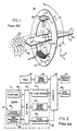
- annular gantry opening 70 is illustrated with a patient slice 42 disposed (support table not illustrated) therein and with respect to a Cartesian coordinate system where the Z-axis is into the Figure and defines a transport axis.
- a source 10 is illustrated in first, second, third and fourth positions as 90, 90', 90" and 90"', respectively.
- source 10 When in the first position, source 10 generates a fan beam 40 which includes a central ray Rc and additional rays diverging therefrom along fan angles, the maximum fan angle being ⁇ .
- the beam angle B is defined as the angle formed by central ray Rc with respect to the vertical Y-axis.
- source 10 When in the fourth position, source 10 generates a fan beam 40"' which also includes a central ray (not illustrated) and rays diverging therefrom to form the fan beam.
- data is collected at least once from every possible beam angle through slice 42 (i.e., the image plane).
- slice 42 i.e., the image plane.
- data corresponding to every beam angle corresponding to a single image plane can be collected after a ( ⁇ + 2 ⁇ )/2 ⁇ rotation about the patient. Because less than an entire rotation about the image plane is required to acquire the imaging data these acquisition methods and systems are generally referred to as half-scan methods and systems. Thus, half-scan acquisition has been employed to reduce acquisition period duration in conjunction with single row detectors.
- half-scan methods and systems also have the advantage of potentially reducing data processing and reconstruction times.
- Single slice detectors, fan beams and half-scans can be used to generate data in several different parallel image planes which, after data acquisition, can be used by a processor to generate an image anywhere between the image planes through interpolation/extrapolation procedures known in the art. For example, assume that during two data acquisition periods first and second data sets were acquired which correspond to first and second parallel acquisition planes, respectively, the planes separated by 0.25 inches. If a user selects an image plane for reconstructing an image which resides between the first and second acquisition planes, interpolation between data in the first and second sets can be used to estimate values of data corresponding to the selected image plane.
- a multi-row detector with a fan beam.
- a relatively thick fan beam is collimated and directed at a multi-row detector with a patient there between, each detector row in effect gathering data for a separate "slice" of the thick fan beam along the Z or translation axis perpendicular to a fan beam width.
- each detector row having a thickness, in these systems it is assumed that the detected signals in each row correspond to a plane centered within the row as projected onto the isocenter Z.
- the central plane through a row will be referred to as a row center
- an interface After data acquisition an interface enables a system user to select an image plane from within the area corresponding to the collected data.
- the selected image plane is between the row centers of at least two adjacent detector rows.
- a processor interpolates between data corresponding to adjacent rows to generate back projection rays corresponding to the selected image plane.
- the processor again identifies an acquired data subset for interpolation, additional processing and back projection.
- One limitation with multi-row detectors is that, during a single acquisition period, data can only be collected which corresponds to the detector thickness.
- To collect additional data corresponding to a greater patient volume after one acquisition period corresponding to a first volume, the patient has to be moved along a translation axis until a second volume which is adjacent the first volume is between the source and detector. Thereafter a second acquisition process has to be performed.
- To collect additional data corresponding to a third volume the patient has to be transported to another relative location with respect to the source and detector.
- Required translation without acquisition necessarily prolong the acquisition period and the additional acquisition time and aligning processes inevitably result in relative discomfort, additional patient movements and undesirable image artifacts.
- Helical scanning systems have been developed so that data can be collected during a single acquisition period without halting patient translation during the acquisition period.
- the source and detector array are mounted on opposing surfaces of an annular gantry and are rotated there around as a patient is transported at constant speed through the gantry.
- the X-ray beam sweeps a helical path through the patient, hence the nomenclature "helical scanning system”.
- Data acquisition can be sped up by increasing operating pitch (i.e., table translation speed relative to gantry rotation rate).
- After data is acquired the data is processed to generate back projection ray estimates and account for data nuances which are caused by the helical acquisition.
- one system combines a multi-row fan beam detector and a fan beam source with a helical scanning procedure to rapidly acquire imaging data using a high pitch/high speed mode.
- an exemplary system including a four row detector may support a 6:1 pitch wherein the detector crosses a reconstruction plane in 0.67 rotations. It is envisioned that an eight slice scanner will be able to support an 11:1 pitch so that the detector crosses a reconstruction plane in 0.73 rotations.
- a cone beam helical scan CT system is known in US 5,663,995.
- Fig. 3 in these high speed helical scanning systems, during acquisition data is acquired with source 10 at position 90, the source and detector are rotated (while data is collected) about gantry opening 70 as the patient 42 is transported there through.
- a processor collects data during transport and rotation from many different beam and fan angles. After source 10 rotates through a complete rotation and reaches position 90 again, additional data is gathered at that position. Because the patient 42 is transported along the Z axis during acquisition, while source 10 is at the same location 90 relative to opening 70 at the beginning and at the end of the rotation, the source and data collected are at a different Z location relative to patient 42.
- data collected for the same beam and fan angles but at different Z locations will be referred to as consecutively collected data.
- a CT scanner for use with the present invention includes a gantry 20 having an opening (70 in Fig. 3) supporting an x-ray source 10 oriented to project a fan beam 40 of x-rays along the beam axis 41 through a patient 42 to a supported and opposed detector array 44.
- the gantry 20 rotates to swing the beam axis within a gantry plane 38 defining the x-y plane of a Cartesian coordinate system. Rotation of the gantry 20 is measured by beam angle ⁇ from an arbitrary reference position within the gantry plane 38.
- a patient 42 resets on a table 46 which may be moved along a translation axis 48 aligned with the Z-axis of the Cartesian coordinate system.
- Table 46 crosses gantry plane 38 and is radiotranslucent so as not to interfere with the imaging process.
- the x-rays of the fan beam 40 diverge from the beam axis 41 within the gantry plane 38 across a transverse axis 50 generally orthogonal to both the beam axis 41 and the translation axis 48 at a fan beam angle (.
- the x-rays of beam 40 also diverge slightly from the beam axis 41 and the gantry plane 38 across the translation axis 48.
- a maximum beam angle ⁇ is identified by symbol ⁇ .
- detector array 44 After passing through patient 42, the x-rays of the fan beam 40 are received by detector array 44 which has multiple columns of detector elements 18'.
- the detector elements 18' are arranged in rows extending along the traverse axis 50 and columns extending along the translation axis 48.
- the surface of detector array 44 may be planar or may follow a section of a sphere or cylinder having a center at focal spot 26 or alternatively at the system isocenter.
- the detector elements 18' each receive x-rays and provide intensity measurements along separate rays of the fan beam 40.
- Each intensity measurement describes the attenuation via a line integral of one fan beam ray passing through a portion of volume 43 of patient 42.
- volume 43 is greater than the slice volume measured by a conventional single slice fan beam CT system and the width of the detector array 44 is measured along its columns.
- volume 43 is typically larger than the slice volume measured by a conventional fan beam CT system, and the width of the detector array 44 as measured along its columns is typically larger than the width of a single slice detector.
- the rows of detector elements 18' subdivide the fan beam detector array along the Z-axis.
- an exemplary control system for controlling the CT imaging system of Fig. 1 has gantry associated control modules 52 which include an x-ray control 54, a gantry motor control 56, a data acquisition system 62 and an imagery constructor 68.
- the x-ray control 54 provides power and timing signals to the x-ray source 10 to turn it on and off as required under the control of a computer 60.
- the gantry motor control 56 controls the rotational speed and position of the gantry 20 and provides information to the computer 60 regarding gantry position.
- the data acquisition system 62 samples and digitizes intensity signals from the detector elements 18' of detector array 44 and the imagery constructor 68 receives the sampled and digitized intensity signals from the data acquisition system 62 each identified as to column and row of the detector element of the detector array 44, and combines the intensity signals from the detector elements 18' according to the present invention, and performs high speed imagery construction according to methods known in the art.
- Each of the above modules is connected to its associated elements on the gantry 20 via slip rings 64 and serves to interface processor or computer 60 for performing various gantry functions.
- Slip rings 64 permit gantry 20 to rotate continuously through angles greater than 360° to acquire projection data.
- the speed and position of table 46 along the translation axis 48 is communicated to and controlled by computer 60 by means of table motor control 58.
- computer/processor 60 runs a pulse sequencing program to perform the inventive data processing method as described in more detail below.
- the computer 60 receives commands and scanning parameters via operator console 65 which is generally a CRT display and keyboard. Console 65 allows an operator to enter parameters for controlling a data acquiring scan and to display the reconstructed image and other information from the computer 60.
- a mass storage device or memory 66 provides a means for storing operating programs for the CT imaging system, as well as image data for future reference by the operator.
- Both computer 60 and the image constructor have associated electronic memory (not shown) for storing data.
- the gantry motor control 56 brings the gantry 20 up to a rotational speed and the table motor control begins translation of the table 46.
- the x-ray control 54 turns on the x-ray source 10 and projection data is acquired on the continuous basis.
- the projection data acquired comprises intensity signals corresponding to each detector element 18' at each particular column and row of array 44.
- half-scan e.g., less than an entire source rotation
- a half-scan rotation requires only a fraction of the time required to perform a complete rotation and therefore acquisition time is appreciably reduced. Because acquisition period duration is reduced, likelihood of patient movement and hence image artifacts is also appreciably reduced.
- the processing time is at least in part dependent upon the amount of data which must be processed to generate an image.
- an image can be reconstructed using data corresponding to a fraction of a full rotation of the source about the patient as opposed to previous high speed helical systems which required data corresponding to more than a full source rotation about the patient.
- Clearly image processing time is appreciably reduced (e.g., processing time is almost halved in some cases). By reducing processing time a more user friendly interface which processes and displays images more quickly can be configured.
- the data generated during a high speed half-scan is insufficient for the purposes of image processing via interpolation of simultaneously collected data (i.e., from data collected with the source in a single location relative to the patient.
- the data set corresponding to a specific image plane and a specific beam angle is said to be a "complete data set" when a detector array (e.g., 44 in Fig. 1) simultaneously collects data on either side of the image plane.
- the data set corresponding to a specific image plane and beam angle is said to be an "incomplete data set" when a detector array does not simultaneously collect data on either side of the image plane (i.e., for the plane and angle the array only collects data on one side of the image plane).
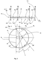
- FIG. 4 a schematic diagram illustrating an exemplary four row detector 44 is illustrated wherein the rows extend into the Figure.
- the four rows are identified by numerals 72, 74, 76 and 78, respectively, and together define a thickness between detector edges 100 and 102.
- Detectors 72 and 78 are edge detectors because they are on the ends of detector 44.
- Each row 72, 74, 76 and 78 has a row center 80, 82, 84 and 86, respectively.
- processor 60 When data is collected by a detector row, processor 60 (see Fig. 2) assumes that the data is all collected at the corresponding row center as opposed to throughout the thickness of the row. For example, with respect to row 72, processor 60 assumes all data was collected at row center 80 and for row 74 processor 60 assumes all data was collected at row center 82 and so on. Referring to Figs. 1 and 4, detector 44 is positioned on gantry 20 such that rows 72 through 78 are orthogonal to translation axis 48 and extend along transverse axis 50.
- a system user prior to data acquisition, a system user will have performed some perfunctory exploratory imaging and hence will generally know the location of a desired image plane with respect to a patient's anatomy.
- the user could limit data acquisition to a data set which includes just enough data (e.g., data corresponding to a half-scan) for reconstructing an image corresponding to the desired plane.
- the user may not know the exact image plane desired and therefore may want to acquire data corresponding to a patient volume (e.g., 43 in Fig. 1) from which subsets of data can be extracted for reconstructing images in specific image planes.
- the actual plane through volume 43 which will be selected for imaging purposes is unknown.
- the image plane through volume 43 is selected subsequent to data acquisition via console 65 after which a specific set of the acquired data is selected for image processing. Nevertheless, for the purpose of simplifying this explanation, it will be assumed that we know the location of a specific image plane during data acquisition. This assumption enables one to easily visualize the spatial relationship between the specific image plane and relative to detectors 72 through 78.
- FIG. 4 an exemplary image plane Pi is illustrated in four separate positions with respect to detector 44, the four separate positions identified by numerals 90, 90', 90" and 90"'.
- the four positions 90, 90', etc. correlate to four separate snapshots in time during a single data acquisition period as detector 44 is rotated about gantry opening 70 (see also Fig. 3) and patient 42, including the patient slice corresponding to image plane Pi, is translated through opening 70.
- image plane positions 90, 90', 90" and 90"' in Fig. 4 correspond to like numbered source positions in Fig. 3.
- image plane Pi is between adjacent detector row centers and during other instances and corresponding beam angles, image plane Pi is not between adjacent detector row centers.
- image plane Pi is not between adjacent detector row centers.
- source 10 and image plane Pi are at position 90, plane Pi is not between two detector row centers.
- position 90' plane Pi is between row centers 84 and 86.
- position 90" plane Pi is between row centers 80 and 82 and at position 90"' plane Pi is not between adjacent row centers.
- processor 60 interpolate between adjacent detector row data to estimate back projection rays for the image plane Pi and source positions 90' and 90" (see Fig. 3) while at positions 90 and 90"' interpolation between simultaneously collected data is not possible and extrapolation is required.
- processor 60 performs the interpolation and/or extrapolation processes on a half-scan data set corresponding to plane Pi generating the estimated back projection data as described above. Thereafter half-scan weights are applied to the estimated back projection data to generate weighted back projection data and the weighted data is then combined via any of several well known back projection techniques to generate an image.
- the half-scan weights can be derived using several different half-scan algorithms. To this end, refer to the article entitled "Optimal Short Scan Convolution for Fanbeam CT" which was authored by D.L. Parker and which was published in Med. Physics Volume 9(2) in March, 1982. Nevertheless, the invention contemplates at least one preferred algorithm wherein the half-scan weights W HS for scan data acquired with the source angle between 0 and 2 ⁇ and centered on ⁇ are given by solving the following equation:
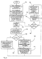
- processor 60 has been preprogrammed with two separate numbers including the number (# rhsr ) of rotations required for half-scan reconstruction for the specific system configuration used with processor 60 and the number (# rcr ) of rotations required for detector 44 to cross a single image plane given a specific pitch supported by the system.
- # rhsr (B+ 2 ⁇ )/(2B) where ⁇ is the maximum fan beam angle ( see Fig. 3).
- processor 60 controls the system of Figs. 1 and 2 to acquire high speed/high pitch data for several helical rotations and corresponding to volume 43 of patient 42.
- the acquired data is stored in storage unit 66.
- a system operator uses console 65 to indicate one of a plurality of different image planes through volume 43 for which an image should be generated.
- processor 60 accesses data corresponding to # rhsr /2 rotations (i.e., corresponding to half the data required for half-scan reconstruction of either side of the image plane Pi) on either side of the image plane Pi from mass storage unit 66.
- processor 60 determines whether or not the number of # rhsr of rotations required for half-scan reconstruction is greater than the number # rcr of rotations required for the detector 44 to cross the image plane. If the number # rhsr of rotations required for half-scan reconstruction is not greater than the number # rcr of rotations required for the detector to cross the image plane Pi, control passes to block 160.
- processor 60 interpolates between simultaneously collected data for all data corresponding to # rhsr /2 rotations on either side of Pi and for each fan beam angle ⁇ and ray angle ⁇ . After interpolation at block 160, control passes to block 162.
- interpolation can be used to identify data for generating an image in an image plane corresponding to certain beam angles while extrapolation must be used to generate data for forming the image from other beam angles.
- processor 60 interpolates between simultaneously collected data for all data corresponding to # rcr /2 rotations on either side of image plane Pi.
- processor 60 extrapolates between simultaneously collected data for all data within # rhsr /2 rotations on either side of the image plane Pi and outside # rcr /2 rotations on either side of the image plane Pi. In other words, extrapolation is used to estimate projection values within the image plane only where interpolation is impossible. After extrapolation at block 170, control passes to block 162.
- processor 160 calculates half-scan weights for each estimated backprojection value generating weighted values by solving equations 1 and 2 above. In the alternative, other half-scan weight algorithms are contemplated.
- processor 60 backprojects the weighted value data to generate an image and display the image on operator console 65. Until another command is received from the system operator at block 166, control continues to loop back up to block 164 and the image is displayed.
- control passes to block 154 and the process loops once again through the lower portion of Fig. 5 until an image corresponding to the newly selected image plane Pi is generated and displayed at block 164.
Landscapes
- Health & Medical Sciences (AREA)
- Life Sciences & Earth Sciences (AREA)
- Engineering & Computer Science (AREA)
- Medical Informatics (AREA)
- Radiology & Medical Imaging (AREA)
- Molecular Biology (AREA)
- Biophysics (AREA)
- Nuclear Medicine, Radiotherapy & Molecular Imaging (AREA)
- Optics & Photonics (AREA)
- Pathology (AREA)
- Physics & Mathematics (AREA)
- Biomedical Technology (AREA)
- Heart & Thoracic Surgery (AREA)
- High Energy & Nuclear Physics (AREA)
- Surgery (AREA)
- Animal Behavior & Ethology (AREA)
- General Health & Medical Sciences (AREA)
- Public Health (AREA)
- Veterinary Medicine (AREA)
- Pulmonology (AREA)
- Theoretical Computer Science (AREA)
- Apparatus For Radiation Diagnosis (AREA)
Applications Claiming Priority (2)
| Application Number | Priority Date | Filing Date | Title |
|---|---|---|---|
| US09/470,411 US6301325B1 (en) | 1999-12-22 | 1999-12-22 | Half-scan algorithm for use with a high speed multi-row fan beam helical detector |
| US470411 | 1999-12-22 |
Publications (3)
| Publication Number | Publication Date |
|---|---|
| EP1110505A2 EP1110505A2 (en) | 2001-06-27 |
| EP1110505A3 EP1110505A3 (en) | 2003-05-14 |
| EP1110505B1 true EP1110505B1 (en) | 2005-04-20 |
Family
ID=23867543
Family Applications (1)
| Application Number | Title | Priority Date | Filing Date |
|---|---|---|---|
| EP00311578A Expired - Lifetime EP1110505B1 (en) | 1999-12-22 | 2000-12-21 | Half-scan algorithm for a high speed multi-row detector |
Country Status (5)
| Country | Link |
|---|---|
| US (1) | US6301325B1 (enExample) |
| EP (1) | EP1110505B1 (enExample) |
| JP (1) | JP2001218763A (enExample) |
| DE (1) | DE60019537T2 (enExample) |
| IL (1) | IL140253A (enExample) |
Families Citing this family (20)
| Publication number | Priority date | Publication date | Assignee | Title |
|---|---|---|---|---|
| JP4796739B2 (ja) * | 2000-09-29 | 2011-10-19 | ジーイー・メディカル・システムズ・グローバル・テクノロジー・カンパニー・エルエルシー | 多数の検出器行によるctのための心臓螺旋ハーフスキャン再構成 |
| US6463118B2 (en) | 2000-12-29 | 2002-10-08 | Ge Medical Systems Global Technology Company, Llc | Computed tomography (CT) weighting for high quality image recontruction |
| US6490334B1 (en) * | 2001-06-29 | 2002-12-03 | Ge Medical Systems Global Technology Company, Llc | Methods and apparatus for high pitch helical computed tomography image reconstruction |
| US6404842B1 (en) | 2001-10-15 | 2002-06-11 | Ge Medical Systems Global Technology Company, Llc | Method and apparatus for image reconstruction in twin helical computed tomographic systems |
| US6885764B2 (en) * | 2001-11-21 | 2005-04-26 | Ge Medical Systems Global Technology Company, Llc | High Speed Z-smoothing method and apparatus for CT imaging system |
| US7006591B2 (en) * | 2002-09-09 | 2006-02-28 | Kabushiki Kaisha Toshiba | Computed tomography apparatus and program |
| US7013034B2 (en) * | 2002-10-10 | 2006-03-14 | Ge Medical Systems Global Technology Company, Llc | Methods and apparatus for reconstructing an image of an object |
| WO2004036251A2 (en) * | 2002-10-15 | 2004-04-29 | Digitome Corporation | Ray tracing kernel |
| US6983034B2 (en) * | 2003-02-14 | 2006-01-03 | University Of Iowa Research Foundation | Methods and devices for CT reconstruction using a grangeat approach |
| US7412029B2 (en) | 2003-06-25 | 2008-08-12 | Varian Medical Systems Technologies, Inc. | Treatment planning, simulation, and verification system |
| CN100518645C (zh) * | 2003-09-29 | 2009-07-29 | Ge医疗系统环球技术有限公司 | 图像重构、投影数据评价方法及计算x线体层照相装置 |
| JP4201686B2 (ja) * | 2003-11-04 | 2008-12-24 | ジーイー・メディカル・システムズ・グローバル・テクノロジー・カンパニー・エルエルシー | X線ct装置 |
| JP4342274B2 (ja) | 2003-11-04 | 2009-10-14 | ジーイー・メディカル・システムズ・グローバル・テクノロジー・カンパニー・エルエルシー | X線ct装置 |
| SE526371C2 (sv) | 2003-12-01 | 2005-08-30 | Xcounter Ab | Anordning och förfarande för att erhålla tomografi-, tomosyntes- och stillbildsdata för ett objekt |
| JP4222930B2 (ja) * | 2003-12-10 | 2009-02-12 | ジーイー・メディカル・システムズ・グローバル・テクノロジー・カンパニー・エルエルシー | 3次元逆投影方法および装置並びにx線ct装置 |
| JP2005177203A (ja) * | 2003-12-22 | 2005-07-07 | Ge Medical Systems Global Technology Co Llc | 複数位置のct画像生成方法およびx線ct装置 |
| JP4091008B2 (ja) | 2004-03-09 | 2008-05-28 | ジーイー・メディカル・システムズ・グローバル・テクノロジー・カンパニー・エルエルシー | Ct画像生成方法およびx線ct装置 |
| US20060090782A1 (en) * | 2004-11-01 | 2006-05-04 | Paul Bergman | Walking aid device |
| JP6202855B2 (ja) * | 2013-03-29 | 2017-09-27 | キヤノン株式会社 | 画像処理装置、画像処理装置の制御方法、及びプログラム |
| CN105093342B (zh) * | 2014-05-14 | 2017-11-17 | 同方威视技术股份有限公司 | 螺旋ct系统及重建方法 |
Family Cites Families (7)
| Publication number | Priority date | Publication date | Assignee | Title |
|---|---|---|---|---|
| JP2914891B2 (ja) * | 1995-07-05 | 1999-07-05 | 株式会社東芝 | X線コンピュータ断層撮影装置 |
| US5559847A (en) * | 1995-12-06 | 1996-09-24 | General Electric Company | Systems, methods and apparatus for reconstructing images in a CT system implementing a helical scan |
| US5606585A (en) | 1995-12-21 | 1997-02-25 | General Electric Company | Methods and apparatus for multislice helical image reconstruction in a computer tomography system |
| US5663995A (en) * | 1996-06-06 | 1997-09-02 | General Electric Company | Systems and methods for reconstructing an image in a CT system performing a cone beam helical scan |
| US5818896A (en) | 1996-11-18 | 1998-10-06 | General Electric Company | Methods and apparatus for three-dimensional and maximum intensity projection image reconstruction in a computed tomography system |
| US5960056A (en) * | 1997-07-01 | 1999-09-28 | Analogic Corporation | Method and apparatus for reconstructing volumetric images in a helical scanning computed tomography system with multiple rows of detectors |
| JP3124254B2 (ja) * | 1997-07-24 | 2001-01-15 | ジーイー横河メディカルシステム株式会社 | 放射線断層撮影装置 |
-
1999
- 1999-12-22 US US09/470,411 patent/US6301325B1/en not_active Expired - Fee Related
-
2000
- 2000-12-12 IL IL14025300A patent/IL140253A/xx not_active IP Right Cessation
- 2000-12-21 DE DE60019537T patent/DE60019537T2/de not_active Expired - Fee Related
- 2000-12-21 EP EP00311578A patent/EP1110505B1/en not_active Expired - Lifetime
- 2000-12-21 JP JP2000388008A patent/JP2001218763A/ja not_active Withdrawn
Also Published As
| Publication number | Publication date |
|---|---|
| EP1110505A2 (en) | 2001-06-27 |
| DE60019537T2 (de) | 2006-02-16 |
| DE60019537D1 (de) | 2005-05-25 |
| JP2001218763A (ja) | 2001-08-14 |
| US6301325B1 (en) | 2001-10-09 |
| IL140253A0 (en) | 2002-02-10 |
| EP1110505A3 (en) | 2003-05-14 |
| IL140253A (en) | 2005-05-17 |
Similar Documents
| Publication | Publication Date | Title |
|---|---|---|
| EP1110505B1 (en) | Half-scan algorithm for a high speed multi-row detector | |
| US5991356A (en) | Radiation tomography method and apparatus | |
| US7327822B2 (en) | Methods, apparatus, and software for reconstructing an image | |
| US6678346B2 (en) | Cone-beam CT scanner with image reconstruction using multiple sub-images | |
| US6459754B1 (en) | Methods and apparatus for cone beam multislice CT correction | |
| US7054475B2 (en) | Apparatus and method for volumetric reconstruction of a cyclically moving object | |
| JP4606414B2 (ja) | 円錐形状光線束を用いるコンピュータ断層撮影方法 | |
| US6778630B2 (en) | Method and system for reconstructing computed tomography images using redundant data | |
| US6490335B1 (en) | Helical segment image reconstruction | |
| WO2006073584A2 (en) | Cone-beam filtered backprojection image reconstruction method for short trajectories | |
| JP2006314856A (ja) | 物体の断層写真画像を発生するシステム及び体積測定式計算機式断層写真法装置 | |
| US6339632B1 (en) | Multi slice single filtering helical weighting method and apparatus to use the same | |
| US6381297B1 (en) | High pitch reconstruction of multislice CT scans | |
| US6522714B1 (en) | Row-wise full helical view weighting method and apparatus for CT scanners | |
| US6885764B2 (en) | High Speed Z-smoothing method and apparatus for CT imaging system | |
| JP4993163B2 (ja) | 傾斜円錐形ビームデータの再構成のための方法及び装置 | |
| CN100581471C (zh) | 用于检查周期性运动的对象的ct方法 | |
| JP2006527618A (ja) | 余剰な測定値を使用するコンピュータ断層撮影法 | |
| JPH08187240A (ja) | コンピュータ断層撮影装置 | |
| EP1694211A1 (en) | Computer tomography method for periodically moving objects | |
| JPH08505309A (ja) | 多重列検出器配列体を有する螺旋走査計算機式断層撮影装置用の再構成法 | |
| JP2002177257A (ja) | X線コンピュータ断層撮影装置 |
Legal Events
| Date | Code | Title | Description |
|---|---|---|---|
| PUAI | Public reference made under article 153(3) epc to a published international application that has entered the european phase |
Free format text: ORIGINAL CODE: 0009012 |
|
| AK | Designated contracting states |
Kind code of ref document: A2 Designated state(s): AT BE CH CY DE DK ES FI FR GB GR IE IT LI LU MC NL PT SE TR |
|
| AX | Request for extension of the european patent |
Free format text: AL;LT;LV;MK;RO;SI |
|
| PUAL | Search report despatched |
Free format text: ORIGINAL CODE: 0009013 |
|
| AK | Designated contracting states |
Designated state(s): AT BE CH CY DE DK ES FI FR GB GR IE IT LI LU MC NL PT SE TR |
|
| AX | Request for extension of the european patent |
Extension state: AL LT LV MK RO SI |
|
| RIC1 | Information provided on ipc code assigned before grant |
Ipc: 7G 06T 11/00 B Ipc: 7A 61B 6/03 A |
|
| 17P | Request for examination filed |
Effective date: 20031114 |
|
| AKX | Designation fees paid |
Designated state(s): DE NL |
|
| GRAP | Despatch of communication of intention to grant a patent |
Free format text: ORIGINAL CODE: EPIDOSNIGR1 |
|
| GRAS | Grant fee paid |
Free format text: ORIGINAL CODE: EPIDOSNIGR3 |
|
| GRAA | (expected) grant |
Free format text: ORIGINAL CODE: 0009210 |
|
| AK | Designated contracting states |
Kind code of ref document: B1 Designated state(s): DE NL |
|
| REG | Reference to a national code |
Ref country code: IE Ref legal event code: FG4D |
|
| REF | Corresponds to: |
Ref document number: 60019537 Country of ref document: DE Date of ref document: 20050525 Kind code of ref document: P |
|
| PLBE | No opposition filed within time limit |
Free format text: ORIGINAL CODE: 0009261 |
|
| STAA | Information on the status of an ep patent application or granted ep patent |
Free format text: STATUS: NO OPPOSITION FILED WITHIN TIME LIMIT |
|
| 26N | No opposition filed |
Effective date: 20060123 |
|
| PGFP | Annual fee paid to national office [announced via postgrant information from national office to epo] |
Ref country code: NL Payment date: 20071223 Year of fee payment: 8 |
|
| PGFP | Annual fee paid to national office [announced via postgrant information from national office to epo] |
Ref country code: DE Payment date: 20080131 Year of fee payment: 8 |
|
| NLV4 | Nl: lapsed or anulled due to non-payment of the annual fee |
Effective date: 20090701 |
|
| PG25 | Lapsed in a contracting state [announced via postgrant information from national office to epo] |
Ref country code: DE Free format text: LAPSE BECAUSE OF NON-PAYMENT OF DUE FEES Effective date: 20090701 |
|
| PG25 | Lapsed in a contracting state [announced via postgrant information from national office to epo] |
Ref country code: NL Free format text: LAPSE BECAUSE OF NON-PAYMENT OF DUE FEES Effective date: 20090701 |