EP1109880B1 - Process for production of aromatics in parallel reformers - Google Patents
Process for production of aromatics in parallel reformers Download PDFInfo
- Publication number
- EP1109880B1 EP1109880B1 EP99945063A EP99945063A EP1109880B1 EP 1109880 B1 EP1109880 B1 EP 1109880B1 EP 99945063 A EP99945063 A EP 99945063A EP 99945063 A EP99945063 A EP 99945063A EP 1109880 B1 EP1109880 B1 EP 1109880B1
- Authority
- EP
- European Patent Office
- Prior art keywords
- hydrogen
- catalyst
- acidic
- reforming
- reformer
- Prior art date
- Legal status (The legal status is an assumption and is not a legal conclusion. Google has not performed a legal analysis and makes no representation as to the accuracy of the status listed.)
- Expired - Lifetime
Links
Images

Classifications
-
- C—CHEMISTRY; METALLURGY
- C10—PETROLEUM, GAS OR COKE INDUSTRIES; TECHNICAL GASES CONTAINING CARBON MONOXIDE; FUELS; LUBRICANTS; PEAT
- C10G—CRACKING HYDROCARBON OILS; PRODUCTION OF LIQUID HYDROCARBON MIXTURES, e.g. BY DESTRUCTIVE HYDROGENATION, OLIGOMERISATION, POLYMERISATION; RECOVERY OF HYDROCARBON OILS FROM OIL-SHALE, OIL-SAND, OR GASES; REFINING MIXTURES MAINLY CONSISTING OF HYDROCARBONS; REFORMING OF NAPHTHA; MINERAL WAXES
- C10G59/00—Treatment of naphtha by two or more reforming processes only or by at least one reforming process and at least one process which does not substantially change the boiling range of the naphtha
- C10G59/06—Treatment of naphtha by two or more reforming processes only or by at least one reforming process and at least one process which does not substantially change the boiling range of the naphtha plural parallel stages only
Definitions
- the present invention relates to reforming a full-boiling range hydrocarbon feed in two parallel stages while maximizing the catalyst life of the heavy cut reformer.
- the reforming of petroleum hydrocarbon streams is an important petroleum refining process that is employed to provide high-octane hydrocarbon blending components for gasoline.
- the process is usually practiced on a straight run naphtha fraction that has been hydrodesulfurized.
- Straight run naphtha is typically highly paraffinic in nature, but may contain significant amounts of naphthenes and minor amounts of aromatics or olefins.
- the reactions include dehydrogenation, cyclization, isomerization, and hydrocracking.
- the dehydrogenation reactions typically will be the dehydroisomerization of alkylcyclopentanes to aromatics, the dehydrogenation of paraffins to olefins, the dehydrogenation of cyclohexanes to aromatics, and the dehydrocyclization of paraffins to aromatics.
- the aromatization of the n-paraffins to aromatics is generally considered to be the most important because of the high octane of the resulting aromatic product compared to the low octane ratings for n-paraffins.
- the isomerization reactions include isomerization of n-paraffins to isoparaffins, and the isomerization of substituted aromatics.
- the hydrocracking reactions include the hydrocracking of paraffins and hydrodesulfurization of any sulfur that is remaining in the feedstock.
- catalysts are capable of reforming petroleum naphthas and hydrocarbons that boil in the gasoline boiling range.
- catalysts useful for reforming include platinum and optionally rhenium or iridium on an alumina support, platinum on zeolite X and zeolite Y, platinum on intermediate pore size zeolites as described in U.S. Patent No. 4,347,394, and platinum on cation exchanged zeolite L.
- U.S. Patent No. 4,104,320 discloses the dehydrocyclization of aliphatic hydrocarbon to aromatics by contact with a catalyst comprising a zeolite L containing alkali metal ions and a Group VIII metal such as platinum.
- the conventional reforming catalyst is a bifunctional catalyst that contains a metal hydrogenation-dehydrogenation component, which is usually dispersed on the surface of a porous inorganic oxide support, usually alumina.
- a metal hydrogenation-dehydrogenation component which is usually dispersed on the surface of a porous inorganic oxide support, usually alumina.
- Platinum has been widely used commercially in the production of reforming catalysts, and platinum on alumina catalysts have been commercially employed in refineries for the past few decades. More recently, additional metallic components have been added to the platinum to further promote the activity or selectivity, or both. Examples of such metallic components are iridium, rhenium, tin and the like. Some catalysts possess superior activity, or selectivity, or both as contrasted with other catalysts. Platinum-rhenium catalysts, for example, possess high selectivity in comparison to platinum catalysts. Selectivity is generally defined as the ability of the catalyst to produce high yields of desirable products with concurrent low production of undesirable products, such as gaseous hydrocarbons
- U.S. Patent No. 2,867,576 discloses separating straight run naphtha into lower and higher boiling cuts, in which the higher boiling cuts are reformed with a hydrogenation-dehydrogenation catalyst with the liquid reformate produced being routed to an aromatics separation process.
- the paraffinic fraction obtained from the separation process is blended with the lower boiling naphtha fraction and the resulting blend is reformed with a reforming catalyst, which may or may not be the same type employed in reforming the high boiling cut.
- U.S. Patent No. 2,944,959 discloses fractionating a full straight run gasoline into a light paraffinic fraction, C 5 and C 6 , that is hydroisomerized with hydrogen and a platinum-alumina catalyst, a middle fraction that is catalytically reformed with hydrogen and a platinum-alumina catalyst, and a heavy fraction that is catalytically reformed with a molybdenum oxide catalyst and recovering the liquid products.
- U.S. Patent Nos. 3,003,949, 3,018,244 and 3,776,949 also disclose fractionating a feed into a C 5 and C 6 fraction, that is isomerized, and a heavier fraction that is reformed.
- U.S. Patent Nos. 3,172,841 and 3,409,540 disclose separating a hydrocarbon feedstock into fractions and catalytically reforming various fractions of the feed
- U.S. Patent No. 4,167,472 discloses separating straight chain from non-straight chain C 6 -C 10 hydrocarbons and separately converting to aromatics
- U.S. Patent No. 4,358,364 discloses catalytically reforming a C 6 fraction and producing additional benzene by hydrogasifying a C 5 - fraction, a fraction with a boiling point above 300°F (149°C) and the gas stream produced from catalytic reforming.
- U.S. Patent No. 3,753,891 discloses fractionating a straight run naphtha into a light naphtha fraction containing the C 6 and a substantial portion of the C 7 hydrocarbons and a heavy naphtha fraction boiling from about 200° (97°C) to 400°F (204°C); then reforming the light fraction to convert naphthenes to aromatics over a platinum-alumina catalyst or a bimetallic reforming catalyst; separately reforming the heavy faction, then upgrading the reformer effluent of the low boiling fraction over a ZSM-5 type zeolite catalyst to crack the paraffins and recovering an effluent with improved octane rating.
- U.S. Patent No. 4,645,586 discloses parallel reforming of the same hydrocarbon feed with two different reforming catalysts.
- the hydrocarbon feed of a given composition is physically (or mechanically) split into two streams, A & B, which have the same composition.
- Stream A is reformed with an acidic catalyst.
- Stream B is reformed with a non-acidic catalyst.
- the patent is otherwise silent as to the composition of each fraction.
- the acidic bi-functional reforming catalyst is not presulfided.
- U.S. Patent No. 4,897,177 discloses using a monofunctional catalyst to reform a hydrocarbon fraction having less than 10% by volume of C 9+ hydrocarbons.
- This fraction is either a C 6 , C 7 , C 8 , C 6 -C 7 , C 7 -C 8 , or C 6 -C 8 fraction, with the most preferred being a C 6 -C 8 fraction.
- That fraction can contain up to 15 vol.% hydrocarbons outside the named range (col. 3, line 44-49).
- a heavier fraction can be reformed using a bifunctional catalyst on an acidic metal oxide. That bifunctional catalyst can be a Pt/Sn/alumina catalyst.
- U.S. Reissue Patent No. 33,323 discloses solvent extraction of a light fraction of a reformate. The goal of that patent is to maximize benzene production only.
- a hydrocarbon feed is separated into a lighter fraction (a C 6 cut that contains 15-35 lv% C 7 + ) and a heavier fraction (all remaining C 7 and heavier components).
- the lighter fraction is reformed in the presence of a non-acidic catalyst to maximize benzene yield.
- the heavier fraction is reformed in the presence of an acidic catalyst.
- the reformate from the non-acidic catalyst is introduced into an aromatics extraction process where an aromatic extract stream and a non-aromatic raffinate stream are recovered. The raffinate stream can be recycled to the feed.
- U.S. Patent No. 4,483,766 discloses purification of the hydrogen produced by a catalytic reformer followed by recycling of at least a portion of the substantially pure hydrogen to the inlet to the reformer. This patent requires a hydrogen separation/purification zone to remove impurities from the hydrogen produced by the reformer.
- a process for reforming/aromatizing hydrocarbons in two reforming zones operated in parallel comprising:
- the present invention is based on my conception and unexpected finding that the catalyst life of the reformer using the bifunctional acidic catalyst can be significantly improved by preferentially using hydrogen produced by a monofunctional, non-acidic aromatization catalyst instead of the recycle hydrogen from the bifunctional reformer itself.
- the hydrogen purity of the hydrogen stream produced by the monofunctional catalyst is substantially higher than that produced by the bifunctional catalyst.
- Use of such a processing scheme allows an increase in the hydrogen gas purity reaching the bifunctional reformer catalyst while minimizing the total gas flow rate to the reformer.
- An additional advantage of the present invention is that the total compressor horsepower can be minimized for the complex thus reducing the complexity of the plant and thus reducing the capital and/or operating costs.
- the present invention comprises preferential routing of the higher hydrogen purity off gas from the non-acidic, monofunctional reformer to the bifunctional reformer.
- the use of the high hydrogen purity gas from the non-acidic, monofunctional reformer serves to increase the purity of the hydrogen reaching the bifunctional reformer.
- Higher purity hydrogen reaching the bifunctional reformer increases the reactor hydrogen partial pressure, which in turn can serve to increase the catalyst life of the bifunctional catalyst by reducing the rate of coking.
- a constant hydrogen partial pressure can be maintained, due to the higher hydrogen purity, by reducing the hydrogen to hydrocarbon mole ratio.
- This reduction in the mole ratio is achieved by reducing the recycle compressor pumping rate or re-circulation rate, which results in a reduction in the power requirement and hence a utility savings.
- the high purity hydrogen from the non-acidic, monofunctional reformer can supply the entire hydrogen demand of the bifunctional reformer or can supply a portion of the hydrogen demand of the bifunctional reformer. In the latter case, this is accomplished by displacing a portion of the hydrogen recycle for the bifunctional reformer.
- a preferred embodiment of the present invention is a process for reforming a full boiling hydrocarbon feed comprising:
- Another alternative embodiment of the present invention comprises eliminating the need for a recycle compressor entirely for the bifunctional reformer.
- all of the hydrogen to the bifunctional reformer is supplied by the non-acidic, monofunctional reformer on a once-through basis.
- a recycle gas compressor and a recycle gas system is not needed as long as the monofunctional reformer is producing hydrogen.
- the system can also be designed such that the monofunctional reformer recycle gas compressor can be used as a recycle compressor for the bifunctional reformer when the monofunctional reformer is not operating.
- This embodiment of the present invention can provide a significant capital cost saving by eliminating a recycle compressor which is an expensive component of the plant.
- Figure 1 shows a flow diagram of split-feed, two stage reforming using a monofunctional reformer operated in parallel with a bifunctional reformer.
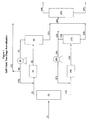
- Figure 2 shows a flow diagram of an embodiment of the present invention where the hydrogen from a monofunctional reformer is preferentially routed to a bifunctional reformer.
- FIG. 1 shows a flow diagram of split-feed, two stage reforming using a monofunctional reformer operated in parallel with a bifunctional reformer.
- Mass flow rates are provided for illustrative purposes only and not intended to limit the scope of the invention.
- Stream (1) is a broad boiling range C 6 to C 10 naphtha that is fed to a C 7 /C 8 splitter column (2).
- the feed rate to the splitter column is 25,755 barrels per operating day (BPOD) (4,095m 3 per operating day (CMPOD)) or approximately 270,014 pounds per hour (lb/hr) (122,476 kg/hr).
- the overhead stream (3) from the C 7 /C 8 splitter is a predominately C 6 -C 7 hydrocarbon feed that is sent to an Aromax reformer (4) containing non acidic Pt L zeolite catalyst.
- the feed rate of the C 6 -C 7 feed to the Aromax reformer is 12,800 BPOD (2,035 CMPOD) or 129,012 lb/hr (58,519 kg/hr). 36,895 lb/hr (16,735 kg/hr) of recycle hydrogen containing gas (stream 10) is combined with the C 6 -C 7 feed that is fed to the Aromax reformer.
- the Aromax reformer is operated at 75 psig (517 kPa gauge).
- the hydrogen to hydrocarbon (H 2 /HC) feed mole ratio for the Aromax reformer is 5/1.
- the effluent from the Aromax reformer (5) goes to a separator (6) to separate the gaseous effluent (stream 7) from the liquid effluent (stream 11).
- the total gaseous effluent (stream 7) which has a mass flow rate of 51,499 lb/hr (23,360 kg/hr) is routed to the recycle compressor (8).
- the compressed gaseous effluent (stream 9) exits the recycle compressor and is divided into a portion that is recycled (stream 10) to the Aromax reformer and a second portion, the net gas make (stream 12), which leaves the process.
- the Aromax reformer gas which is the gaseous effluent from separator (6), has a hydrogen purity of 93.7 mole %. This is also true for the compressed gas (9) and the net gas (12).
- the net gas make (stream 12) is 14,604 lb/hr (6,624 kg/hr).
- the bottoms stream (stream 14) from the C 7 /C 8 splitter (2) is predominately a C 8 -C 10 feed. 12,955 BPOD (2,060 CMPOD) or 141,002 lb/hr (63,957 kg/hr) of the C 8 -C 10 feed is fed to the conventional reformer (15) after combining with recycle gas stream 21.
- the conventional reformer for this illustration of the invention contains a Pt/Sn/Cl on alumina catalyst and is operated at 75 psig (517 kPa gauge).
- the H 2 /HC feed mole ratio is 3/1.
- the hydrogen partial pressure is 59 psia (407 kPa absolute).
- the effluent from the conventional reformer, stream 16 is sent to separator (17) to separate the gaseous effluent (stream 18) from the liquid effluent (stream 23).
- the gaseous effluent (18) has a mass flow rate of 52,694 lb/hr (23,902 kg/hr).
- 30,345 lb/hr (13,764 kg/hr) (stream 19) of the gaseous effluent from separator 17, is passed to the recycle compressor (20) while 22,349 lb/hr (10,137 kg/hr) (stream 22) leaves the process as net gas make.
- the resulting compressed gaseous stream is stream 21.
- the gaseous effluent (stream 18) is 84.9 mole % hydrogen.
- the mass flow rate for stream 21 is 30,345 lb/hr (13,764 kg/hr) and the hydrogen purity is 84.9 mole %.
- the compressed gas (stream 21) is combined with the C 8 -C 10 feed (stream 14) and the combined feed is fed to the conventional reformer (15).
- the liquid effluent (stream 23) from the conventional reformer is combined with the liquid effluent (stream 11) from the Aromax reformer and the combined stream (stream 24) passed to the depentanizer (25).
- the depentanizer In the depentanizer the C 5 - fraction (stream 26) is distilled overhead and the C 6 + fraction (stream 27) is passed on for further processing (not shown). Further processing can include aromatics recovery as well as production of paraxylene and benzene product.
- FIG. 2 shows a preferred embodiment of the present invention. This drawing and description is intended to help illustrate the invention only and is not intended to be limiting.
- Stream (1) is a broad boiling range C 6 to C 10 naphtha that is fed to a C 7 /C 8 splitter column (2).
- the feed rate to the splitter column is 25,755 barrels per operating day (BPOD) (4,095 CMPOD) or approximately 270,014 pounds per hour (lb/hr) (122,476 kg/hr).
- BPOD barrels per operating day
- lb/hr pounds per hour
- the overhead from the C 7 /C 8 splitter, stream 3 is a predominately C 6 -C 7 hydrocarbon feed that is sent to an Aromax reformer (4) containing non acidic Pt L zeolite catalyst.
- the feed rate of the C 6 -C 7 feed to the Aromax reformer is 12,800 BPOD (2,035 CMPOD) or 129,012 lb/hr (58,519 kg/hr). 36,895 lb/hr (16,735 kg/hr) of recycle hydrogen containing gas (stream 10) is combined with the C 6 -C 7 feed that is fed to the Aromax reformer.
- the Aromax reformer is operated at 75 psig (517 kPa gauge).
- the effluent from the Aromax reformer (stream 5) goes to a separator (6) to separate the gaseous effluent (stream 7) from the liquid effluent (stream 11).
- the gaseous effluent is routed to the recycle compressor (8).
- the compressed gaseous effluent (stream 9) exits the recycle compressor and is divided into a portion that is recycled to the Aromax reformer (stream 10), and a second portion, the net gas make (stream 12), which leaves the process and is sent to the conventional reformer circuit as described below.
- the Aromax reformer gas which is the gaseous effluent from separator (6), has a hydrogen purity of 93.7 mole %. This is also true for the compressed gas (9) and the net gas (12).
- the net gas make (stream 12) is 14,604 lb/hr (6,624 kg/hr). None of the net gas make leaves the process via stream 12a.
- the bottoms stream (steam 14) from the C 7 /C 8 splitter is predominately a C 8 -C 10 feed.
- 12,955 BPOD (2,060 CMPOD) or 141,002 lb/hr (63,957 kg/hr) is fed to the conventional reformer (15) after combining with recycle gas stream 21a.
- the conventional reformer for this illustration ofthe invention contains a Pt/Sn/Cl on aluminia catalyst and is operated at 75 psig (517 kPa gauge).
- the H 2 /HC feed mole ratio is 4/1.
- the hydrogen partial pressure is 66 psia (455 kPa absolute).
- the effluent from the conventional reformer, stream 16 is sent to separator (17) to separate the gaseous effluent (stream 18) from the liquid effluent (stream 23).
- the liquid effluent (stream 23) is produced at a rate of 118,653 lb/hr (53,820 kg/hr).
- a portion of the gaseous effluent, namely 15,741 lb/hr (7,140 kg/hr) (stream 19) is passed to the recycle compressor (20) while 36,953 lb/hr (16,762 kg/hr) (stream 22) leaves the process as net gas in this case.
- the resulting compressed gaseous stream is stream 21.
- the gaseous effluent (stream 18) is 84.9 mole % hydrogen. This hydrogen purity is also true for streams 19, 21 and 22.
- Stream 21 the compressed gas from the recycle compressor (20) with a hydrogen purity of 84.9 mole %, is combined with the 14,604 lb/hr (6,624 kg/hr) of Aromax reformer net gas (stream 12b) which has a hydrogen purity of 93.7 mole %.
- the resulting combined gaseous stream 21a has a mass flow rate of 30,345 lb/hr (13,764 kg/hr) and a hydrogen purity of 90.1 mole %.
- the gas in stream 21a is combined with the C 8 -C 10 feed (stream 14) and fed to the conventional reformer (15).
- the liquid effluent (stream 23) from the conventional reformer is combined with 114,408 lb/hr (51,895 kg/hr) of the liquid effluent (stream 11) from the Aromax reformer and the combined stream (stream 24) passed to the depentanizer (25).
- the depentanizer the C 5 - fraction (stream 26) is distilled overhead and the C 6 + fraction (stream 27) is passed on for further processing (not shown). Further processing can include aromatic recovery as well as production of paraxylene and benzene product.
- the present invention involves a process for reforming a full boiling hydrocarbon feed to enhance para-xylene and benzene yields.
- the hydrocarbon feed is separated into a C 5 - cut, a C 6 -C 7 cut, and a C 8 + cut.
- the C 6 -C 7 cut may contain up to 5 lv. % of C 8 + hydrocarbon
- the C 8 + cut may contain up to 10 lv. % of C 7 - hydrocarbon.
- Each of the cuts may contain up to 20 lv. % of hydrocarbons outside the named range.
- the C 6 -C 7 cut is subjected to catalytic aromatization at elevated temperatures in a first reformer in the presence of hydrogen and using a mono-functional non-acidic catalyst comprising at least one Group VIII metal and a non-acidic zeolite support to produce a first reformate stream.
- the C 8 + cut is subjected to catalytic aromatization at elevated temperatures in a second reformer in the presence of hydrogen and using a bi-functional, acidic catalyst comprising at least one Group VIII metal and a metallic oxide support to produce a second reformate stream.
- One of the catalysts used must be a non-acidic catalyst having a non-acidic zeolite support charged with one or more dehydrogenating constituents.
- This catalyst is also referred to as the monofunctional catalyst or as the non-acidic, monofunctional catalyst.
- zeolites useful in the practice of the present invention are zeolite L, zeolite X, zeolite Y, mordenite, and ZSM-10 as well as other zeolite or molecular sieve materials that have a large pore size and preferably have a unidimensional channel structure. These zeolites have apparent pore sizes on the order of 7 to 9 Angstroms.
- L zeolite and "zeolite L” are used synonymously to refer to LTL type zeolite.
- Zeolite L is a synthetic crystalline zeolitic molecular sieve which may be written as: (0.9-1.3)M 2/n O:Al 2 O 3 (5.2-6.9)SiO 2 :yH 2 O wherein M designates a cation, n represents the valence of M, and y may be any value from 0 to about 9.
- M designates a cation
- n represents the valence of M
- y may be any value from 0 to about 9.
- Zeolite L, its X-ray diffraction pattern, its properties, and method for its preparation are described in detail in U.S. Pat. No. 3,216,789.
- U.S. Pat. No. 3,216,789 shows the preferred zeolite of the present invention.
- the real formula may vary without changing the crystalline structure; for example, the mole ratio of silicon to aluminum (Si/Al) may vary from 1.0 to 3.5.
- Zeolite X is a synthetic crystalline zeolitic molecular sieve which may be represented by the formula: (0.7-1.1)M 2/n O:Al 2 O 3 :(2.0-3.0)SiO 2 :yH 2 O wherein M represents a metal, particularly alkali and alkaline earth metals, n is the valence of M, and y may have any value up to about 8 depending on the identity of M and the degree of hydration of the crystalline zeolite.
- Zeolite X is a synthetic crystalline zeolitic molecular sieve which may be written as: (0.7-1.1)Na 2 O:Al 2 O 3 :xSiO 2 :yH 2 O wherein x is a value greater than 3 up to about 6 and y may be a value up to about 9.
- Zeolite Y has a characteristic X-ray powder diffraction pattern which may be employed with the above formula for identification.
- Zeolite Y is described in more detail in U.S. Pat. No. 3,130,007.
- U.S. Pat. No. 3,130,007 shows a zeolite useful in the present invention.
- ZSM-10 is described in more detail in U.S. Patent Number 3,692,470.
- Another reference that describes the synthesis and structure of ZSM-10 is in Zeolites 16:236-244, 1996 written by J. B. Higgins and K. D. Schmitt, and published by Elsevier Sicence Inc.
- the preferred non-acidic catalyst is a type L zeolite charged with one or more dehydrogenating constituents.
- the zeolitic catalysts according to the invention are charged with one or more Group VIII metals, e.g., nickel, ruthenium, rhodium, palladium, iridium or platinum.
- the preferred Group VIII metals are iridium and particularly platinum, which are more selective with regard to dehydrocyclization and are also more stable under the dehydrocyclization reaction conditions than other Group VIII metals.
- the preferred percentage of platinum in the dehydrocyclization catalyst is between 0.1% and 5%, the lower limit corresponding to minimum catalyst activity and the upper limit to maximum activity. This allows for the high price of platinum, which does not justify using a higher quantity of the metal since the result is only a slight improvement in catalyst activity.
- Group VIII metals are introduced into the large-pore zeolite by synthesis, impregnation or exchange in an aqueous solution of appropriate salt.
- the operation may be carried out simultaneously or sequentially.
- platinum can be introduced by impregnating the zeolite with an aqueous solution of tetrammineplatinum (II) nitrate, tetrammineplatinum (II) hydroxide, dinitrodiamino-platinum or tetrammineplatinum (II) chloride.
- platinum can be introduced by using cationic platinum complexes such as tetrammineplatinum (II) nitrate.
- a preferred, but not essential, element of the present invention is the presence of an alkaline earth metal in the dehydrocyclization catalyst.
- That alkaline earth metal can be either barium, strontium or calcium.
- the alkaline earth metal is barium.
- the alkaline earth metal can be incorporated into the zeolite by synthesis, impregnation or ion exchange. Barium is preferred to the other alkaline earths because the resulting catalyst has high activity, high selectivity and high stability.
- An inorganic oxide may be used as a carrier to bind the large-pore zeolite containing the Group VIII metal.
- the carrier can be a natural or a synthetically produced inorganic oxide or combination of inorganic oxides.
- Typical inorganic oxide supports which can be used include clays, alumina, and silica, in which acidic sites are preferably exchanged by cations that do not impart strong acidity.
- the non-acidic catalyst can be employed in any of the conventional types of equipment known to the art. It may be employed in the form of pills, pellets, granules, broken fragments, or various special shapes, disposed as a fixed bed within a reaction zone, and the charging stock may be passed therethrough in the liquid, vapor, or mixed phase, and in either upward or downward flow. Alternatively, it may be prepared in a suitable form for use in moving beds, or in fluidized-solid processes, in which the charging stock is passed upward through a turbulent bed of finely divided catalyst.
- the zeolite L based catalyst is produced by treatment in a gaseous environment in a temperature range between 1025°F (552°C) and 1275°F (691°C) while maintaining the water level in the effluent gas below 1000 ppm.
- the high temperature treatment is carried out at a water level in the effluent gas below 200 ppm.
- Preferred high temperature treated catalysis are described in the Mulaskey et al. patents, U.S. Patent No. 5,382,353 and U.S. Patent No. 5,620,937, particularly high temperature treated Pt L zeolite catalysts.
- the catalyst used in the present invention can comprise Pt and a Group 1B Metal on a halogenated non-acidic zeolite L support as disclosed in copending U.S. Patent Application 09/134,164.
- the acidic catalyst can comprise a metallic oxide support having disposed therein a Group VIII metal. Suitable oxide supports include alumina and silica.
- the acidic catalyst comprises a oxide support having disposed therein in intimate admixture a Group VIII metal (preferably platinum) and a Group VIII metal promoter, such as rhenium, tin, germanium, cobalt, nickel, iridium, rhodium, ruthenium and combinations thereof. More preferably, the acidic catalyst comprises an alumina support, platinum, and rhenium.
- a preferred acidic catalyst comprises platinum and tin on an alumina support.
- the acidic catalyst has not been presulfided before use if there is a risk of contaminating the preferred monofunctional, non-acidic catalyst.
- a presulfided catalyst such as Pt/Re on alumina.
- bifunctional catalysts include platinum on acidic alumina as disclosed in U.S. Patent No. 3,006,841 to Haensel; platinum-rhenium on acidic alumina as disclosed in U.S. Patent No. 3,415,737 to Kluksdahl; platinum-tin on acidic alumina; and platinum-iridium with bismuth on an acidic carrier as disclosed in U.S. Patent No. 3,878,089 to Wilhelm.
- the reforming in both reformers is carried out in the presence of hydrogen at a pressure adjusted to favor the dehydrocyclization reaction thermodynamically and to limit undesirable hydrocracking reactions.
- the pressures used preferably vary from 1 atmosphere (101 kPa absolute) to 500 psig (3447 kPa gauge), more preferably from 50 to 300 psig (345 to 2069 kPa gauge), and still more preferably 40 to 150 psig (276 to 1034 kPa gauge), the molar ratio of hydrogen to hydrocarbons preferably being from 1:1 to 10:1, more preferably from 2:1 to 6:1.
- the dehydrocyclization reaction occurs with acceptable speed and selectivity. If the operating temperature is below 400° C, the reaction speed is insufficient and consequently the yield is too low for industrial purposes.
- the operating temperature of dehydrocyclization is above 600° C., interfering secondary reactions such as hydrocracking and coking occur, and substantially reduce the yield. It is not advisable, therefore, to exceed the temperature of 600° C.
- the preferred temperature range (430° C. to 550° C.) of dehydrocyclization is that in which the process is optimum with regard to activity, selectivity and the stability of the catalyst.
- the particularly preferred non-acidic, monofunctional catalyst used in the present Invention namely Pt L zeolite
- the feed contacting the preferred monofuctional catalyst preferably contains less than 50 ppb sulfur, more preferably less than 10 ppb sulfur.
- U.S. Patent No. 4,456,527 discloses the surprising finding that if the sulfur content of the feed was reduced to ultra low levels, below levels used in the past for catalysts especially sensitive to sulfur, that then long run lengths could be achieved with the L-zeolite non-acidic catalyst. Specifically, it was found that the concentration of sulfur in the hydrocarbon feed to the L-zeolite catalyst should be at ultra low levels to achieve improved stability/activity for the catalyst used.
- a non-acidic, monofunctional reformer produces offgas of surprisingly high purity having 88 to 95 mole % hydrogen content, preferably 90 to 95 %, more preferably 92 to 94% without any special purification.
- a bifunctional, acidic reformer produces an off gas having a hydrogen content lower than this, generally less than 88 mole % hydrogen. Reformers operated at high severity often produce an offgas having a hydrogen purity much less than 88 mole %.
- the difference in hydrogen purities is probably due to the presence of more hydrocracking reactions occurring in the bifunctional reformer due at least in part to the acidic component of the bifunctional catalyst.
- the non-acidic, monofunctional reformer used in the present invention has very little, if any acidic sites on the catalyst.
- Such a catalyst performs predominantly dehydrocyclization, and dehydrogenation reactions and has much lower cracking activity than do bifunctional catalysts. The cracking reactions produce most of the light impurities. It is thought this difference in catalyst functionality accounts for the difference in hydrogen purity of the respective hydrogen gas containing streams produced.
- the present invention is particularly advantageous.
- the feed to the bifunctional reformer may be a C 6 -C 10 cut, a C 7 -C 9 cut, a C 6 -C 8 cut, a C 8 -C 10 cut, or any variation thereof preferably including C 8 nonaromatics.
- Production of paraxylene (PX) from unextracted xylenes is advantageous because it eliminates the extraction step and provides a significant cost saving.
- the present invention is particularly advantageous for producing PX using unextracted xylenes because one can operate the bifunctional reformer at very high octanes without sacrificing the hydrogen purity reaching the bifunctional catalyst.
- Prior art processes would require either a greatly increased recycle rate or a greatly reduced catalyst run length due to a lower Hydrogen to Hydrocarbon mole ratio or a combination of a higher recycle rate and a reduced run length.
- increasing the recycle rate due to lower hydrogen purity requires increased compressor horsepower and demands more energy (higher utility costs). Also more light impurities are fed across the catalyst contributing to coking.
- An alternate embodiment of the invention is a process for making high purity benzene and high purity paraxylene, which includes the step of splitting a naphtha feed stream into a C 7 - light fraction and a C 8 + heavy fraction, then reforming each fraction separately.
- the light fraction may be reformed (aromatized) in the presence of a non-acidic monofunctional catalyst, and the heavy fraction may be reformed (aromatized) in the presence of an acidic bifunctional catalyst.
- the heavy fraction reformate can have a surprisingly high concentration of aromatics, measured as octane number, specifically, an RON of 102 to 108.
- This high octane number can be accomplished under conventional reforming conditions. That is, reforming is done at: pressures varying from 1 atmosphere (101 kPa absolute) to 500 psig (3447 kPa gauge), more preferably from 50 to 300 psig (345 to 2069 kPa gauge); a molar ratio of hydrogen to hydrocarbons from 1:1 to 10:1, more preferably from 2:1 to 6:1; temperatures from 400°C to 600°C, preferably from 430°C to 550°C; and a liquid hourly space velocity of between 0.3 and 5.
- Xylenes isomerization units are also adversely effected by high non-aromatics levels.
- Non-aromatics crack in xylenes isom units forming light byproducts and coking.
- Non-aromatics also take up space in the isom loop displacing xylenes.
- the present invention allows production of a very high octane C 8 aromatic reformate particularly well suited for PX production while also minimizing hydrogen gas recycle rate and/or minimizing fouling rate of the catalyst.
- Prior art processes require either greatly increasing the gas recycle rate to the catalyst or sacrificing catalyst life due to the poor quality hydrogen gas produced at high severities.
- the metal surfaces or the heat exchange surfaces that contact the hydrocarbons and aromatics at elevated temperatures and at ultra low sulfur conditions are made of a material having a resistance to carburization and metal dusting at least as great as that of type 347 stainless steel under low sulfur reforming conditions.
- the metal surfaces of the reformer have a metal-containing coating, cladding, plating, or paint applied to at least a portion (preferably at least 50%, more preferably at least 75% and most preferably to all) of the surface area that is to be contacted with hydrocarbons at process temperature.
- the metal-coated reactor system is preferably heated to produce intermetallic and/or metal carbide layers.
- a preferred metal-coated reactor system preferably comprises a base construction material (such as a carbon steel, a chromium steel, or a stainless steel) having one or more adherent metallic layers attached thereto. Examples of metallic layers include elemental chromium and iron-tin intermetallic compounds such as FeSn 2 .
- metal-containing coating or “coating” is intended to include claddings, platings, paints and other coatings which contain either elemental metals, metal oxides, organometallic compounds, metal alloys, mixtures of these components and the like.
- the metal(s) or metal compounds are preferably a key component(s) of the coating.
- Flowable paints that can be sprayed or brushed are a preferred type of coating.
- the coated steel is heat treated to produce intermetallic compounds, thus reacting the coating metal with the steel.
- metals that interact with, and preferably react with, the base material of the reactor system to produce a continuous and adherent metallic protective layer at temperatures below or at the intended hydrocarbon conversion conditions are especially preferred as they can more readily provide complete coverage of the substrate material.
- metals include those selected from among tin, antimony, germanium, arsenic, bismuth, aluminum, gallium, indium, copper, lead, and mixtures, intermetallic compounds and alloys thereof.
- Preferred metal-containing coatings comprise metals selected from the group consisting of tin, antimony, germanium, arsenic, bismuth, aluminum, and mixtures, intermetallic compounds and alloys of these metals.
- Especially preferred coatings include tin-, antimony-and germanium-containing coatings. These metals will form continuous and adherent protective layers. Tin coatings are especially preferred -- they are easy to apply to steel, are inexpensive and are environmentally benign.
- tin paints may be applied to a (wet) thickness of between 1 to 6 mils (0.0254 to 0.1524 mm), preferably between about 2 to 4 mils (0.0508 to 0.1016 mm).
- the thickness after curing is preferably between about 0.1 to 50 mils (0.00254 to 1.27 mm), more preferably between about 0.5 to 10 mils (0.0127 to 0.254 mm).
- Metal-containing coatings can be applied in a variety of ways, which are well known in the art, such as electroplating, chemical vapor deposition, and sputtering, to name just a few.
- Preferred methods of applying coatings include painting and plating. Where practical, it is preferred that the coating be applied in a paint-like formulation (hereinafter "paint"). Such a paint can be sprayed, brushed, pigged, etc. on reactor system surfaces.
- One especially preferred tin paint contains at least four components or their functional equivalents: (i) a hydrogen decomposable tin compound, (ii) a solvent system, (iii) finely divided tin metal and (iv) tin oxide.
- a hydrogen decomposable tin compound organometallic compounds such as tin octanoate or neodecanoate are particularly useful.
- Component (iv) the tin oxide is a porous tin-containing compound that can sponge-up the organometallic tin compound, and can be reduced to metallic tin.
- the paints preferably contain finely divided solids to minimize settling.
- tin paint containing stannic oxide, tin metal powder, isopropyl alcohol and 20% Tin Ten-Cem (manufactured by Mooney Chemical Inc., Cleveland, Ohio). Twenty percent Tin Ten-Cem contains 20% tin as stannous octanoate in octanoic acid or stannous neodecanoate in neodecanoic acid.
- tin paints are applied at appropriate thicknesses, heating under reducing conditions will result in tin migrating to cover small regions (e.g., welds) which were not painted. This will completely coat the base metal.
- Tin/iron paints are also useful in the present invention.
- a preferred tin/iron paint will contain various tin compounds to which iron has been added in amounts up to one third Fe/Sn by weight.
- the addition of iron can, for example, be in the form of Fe 2 O 3 .
- the addition of iron to a tin containing paint should afford noteworthy advantages; in particular: (i) it should facilitate the reaction of the paint to form iron stannides thereby acting as a flux; (ii) it should dilute the nickel concentration in the stannide layer thereby providing a coating having better protection against coking; and (iii) it should result in a paint which affords the anti-coking protection of iron stannides even if the underlying surface does not react well.
- Some of the coatings are preferably cured, for example, by heat treatment. Cure conditions depend on the particular metal coating and curing conditions that are selected so as to produce an adherent protective layer. Gas flow rates and contacting time depend on the cure temperature used, the coating metal and the specific components of the coating composition.
- the coated materials are preferably cured in the absence of oxygen. If they are not already in the metallic state, they are preferably cured in a hydrogen-containing atmosphere at elevated temperatures. Cure conditions depend on the coating metal and are selected so they produce a continuous and uninterrupted protective layer that adheres to the steel substrate. The resulting protective layer is able to withstand repeated temperature cycling, and does not degrade in the reaction environment. Preferred protective layers are also useful in reactor systems that are subjected to oxidizing environments, such as those associated with coke burn-off.
- the contacting of the reactor system having a metal-containing coating, plating, cladding, paint or other coating applied to a portion thereof with hydrogen is done for a time and at a temperature sufficient to produce a metallic protective layer.
- coated coupons may be heated in the presence of hydrogen in a simple test apparatus; the formation of the protective layer may be determined using petrographic analysis.
- cure conditions result in a protective layer that is firmly bonded to the steel. This may be accomplished, for example, by curing the applied coating at elevated temperatures.
- Metal or metal compounds contained in the paint, plating, cladding or other coatings are preferably cured under conditions effective to produce molten metals and/or compounds.
- germanium and antimony paints are preferably cured between 1000°F (538°C) and 1400°F (760°C).
- Tin paints are preferably cured between 900°F (482°C) and 1100°F (593°C). Curing is preferably done over a period of hours, often with temperatures increasing over time. The presence of hydrogen is especially advantageous when the paint contains reducible oxides and/or oxygen-containing organometallic compounds.
- the system including painted portions can be pressurized with flowing nitrogen, followed by the addition of a hydrogen-containing stream.
- the reactor inlet temperature can be raised to 800°F (427°C) at a rate of 50-100°F/hr (28-56°C/hr). Thereafter the temperature can be raised to a level of 950-975°F (510-524°C) at a rate of 50°F/hr (28°C/hr), and held within that range for about 48 hours.
- a C 8 + naphtha feed was prepared from a C 6 -C 10 wide-boiling range naphtha for reforming over a bifunctional acidic catalyst.
- Feed composition of the C 8+ feed and some of its properties are as follows: Carbon No. Distribution, wt % C 6- 0.05 C 7 9.01 C 8 43.33 C 9 31.92 C 10 15.13 C 11+ 0.56 Paraffins-wt % 65.13 Naphthenes-wt % 15.73 Aromatics-wt % 14.94 Olefins-wt % 0.00 Unclassified 4.20 ASTM D-86 , F LV-% 0 239 10 245 50 275 90 326 100 363 API Gravity 57.9
- the reactor was part of a large unit equipped with a recycle gas compressor system, low temperature separator and a debutanizer.
- the feed from Example 1 was passed over the catalyst charge.
- Operating conditions were a pressure of 75 PSIG, a LHSV of 1-hr -1 , a hydrogen/hydrocarbon feed (H 2 /HC) mole ratio of 3/1 and an average reactor temperature of 943 F (506°C).
- Example 2 was repeated except that the average reactor temperature was increased to 960 degrees F (516°C). In this case, the recycle gas had a lower hydrogen purity than that in Example 2 as shown below.
- a C 6 -C 7 naphtha containing 75 % C 6 and 24 % C 7 with an API Gravity of 73.0 was processed in the same manner as described in Example 2, except that the catalyst charged to the reactor was a non-acidic mono-functional aromatization catalyst.
- the feed contained 4.1 wt % aromatics with the rest being paraffins and naphthenes.
- the catalyst was a Pt containing K/Ba L zeolite (trademark AROMAX).
- Reactor inlet pressure was 75 PSIG, reactor temperature averaged 900°F (482°C) and the H 2 /HC feed mole ratio was 5.0/1. With the separator operating at 96°F (36°C), the recycle gas composition was as follows: Recycle Gas Composition - Mole % Hydrogen 93.7 Hydrocarbon 6.3
- a C 6 -C 10 wide boiling range naphtha was first distilled to provide a C 6 -C 7 overhead cut and a C 8 + bottoms cut.
- the C 8 + bottoms cut is described in Example 1 and the C 6 -C 7 cut is described in Example 4.
- a C 6 -C 10 wide boiling range naphtha was processed as described in Example 5.
- the C 6 -C 10 wide boiling range naphtha was distilled to provide a C 6 -C 7 overhead cut and a C 8 + bottoms cut.
- the C 6 -C 7 cut was aromatized over a non-acidic monofunctional catalyst as described in Example 4, and the C 8 + cut was reformed over a bifunctional acidic reforming catalyst as described in Example 2.
- the net gas (14,604 LB/Hr (6,624 kg/hr)) from the monofunctional non-acidic aromatization catalyst was added to the recycle gas of the bifunctional reforming catalyst, displacing an equal amount of the lower hydrogen purity recycle gas. This displacement is necessary to maintain the material balance.
- the net gas make from the bifunctional reforming catalyst is 36,953 LB/Hr (16,762 kg/hr) as shown in Figure 2 as well as in the detailed description of Figure 2.
- the recycle gas to the bifunctional reforming catalyst is still 30,345 LB/Hr (13,764 kg/hr) as in Example 2, however because of the addition of the higher purity hydrogen gas from the monofunctional aromatization process, the hydrogen purity of the recycle gas to the bifunctional reforming catalyst is now increased to 90.1 %, up from 84.9 %.
- This increased purity in the recycle gas translates to an increase in the H 2 /HC feed mole ratio from 3/1 (as in Example 2) to 4/1. More importantly, the hydrogen partial pressure is increased to 66 PSIA (455 kPa absolute) from 59.3 PSIA (409 kPa absolute) per Example 2.
- This example describes another embodiment of the invention, wherein an increased catalyst life of the bifunctional acidic reforming catalyst is not desired, but where the objective is to maintain a constant H 2 /HC feed mole ratio, i.e. a constant hydrogen partial pressure. Operation in this mode results in a reduction in the electrical utility requirement to operate the recycle compressor. In this example, operation is as described in Example 6, however, the goal is to maintain the same H 2 /HC feed mole ratio of 3/1 for the bifunctional reforming catalyst as in Example 2.
- This 11,900 LB/Hr (5,398 kg/hr) reduction-from 30,345 LB/Hr (13,764 kg/hr) to 18,445 LB/hr (8,367 kg/hr) represents a 39.3 % reduction in the recycle gas mass flow rate.
Landscapes
- Chemical & Material Sciences (AREA)
- Oil, Petroleum & Natural Gas (AREA)
- Engineering & Computer Science (AREA)
- Chemical Kinetics & Catalysis (AREA)
- General Chemical & Material Sciences (AREA)
- Organic Chemistry (AREA)
- Organic Low-Molecular-Weight Compounds And Preparation Thereof (AREA)
- Production Of Liquid Hydrocarbon Mixture For Refining Petroleum (AREA)
- Catalysts (AREA)
Applications Claiming Priority (3)
| Application Number | Priority Date | Filing Date | Title |
|---|---|---|---|
| US9682698P | 1998-08-17 | 1998-08-17 | |
| US96826P | 1998-08-17 | ||
| PCT/US1999/018568 WO2000009633A1 (en) | 1998-08-17 | 1999-08-16 | Process for production of aromatics in parallel reformers |
Publications (2)
| Publication Number | Publication Date |
|---|---|
| EP1109880A1 EP1109880A1 (en) | 2001-06-27 |
| EP1109880B1 true EP1109880B1 (en) | 2003-11-26 |
Family
ID=22259263
Family Applications (1)
| Application Number | Title | Priority Date | Filing Date |
|---|---|---|---|
| EP99945063A Expired - Lifetime EP1109880B1 (en) | 1998-08-17 | 1999-08-16 | Process for production of aromatics in parallel reformers |
Country Status (10)
| Country | Link |
|---|---|
| US (1) | US6143166A (enExample) |
| EP (1) | EP1109880B1 (enExample) |
| JP (1) | JP2002522626A (enExample) |
| AT (1) | ATE255154T1 (enExample) |
| AU (1) | AU5775799A (enExample) |
| CA (1) | CA2339993A1 (enExample) |
| DE (1) | DE69913164T2 (enExample) |
| ES (1) | ES2212622T3 (enExample) |
| MX (1) | MXPA01001723A (enExample) |
| WO (1) | WO2000009633A1 (enExample) |
Families Citing this family (49)
| Publication number | Priority date | Publication date | Assignee | Title |
|---|---|---|---|---|
| RU2289610C1 (ru) * | 2005-08-05 | 2006-12-20 | Владимир Борисович Марышев | Способ переработки широкой бензиновой фракции |
| US8323363B2 (en) * | 2007-08-30 | 2012-12-04 | Innovative Energy Solution | Reformation of hydrogen-containing fluids in a cyclic flow reactor |
| US20090166259A1 (en) * | 2007-12-28 | 2009-07-02 | Steven Bradley | Metal-based coatings for inhibiting metal catalyzed coke formation in hydrocarbon conversion processes |
| US20090320370A1 (en) * | 2008-06-30 | 2009-12-31 | Fecteau David J | Catalytic Reformer Recycle Gas Compressor Efficiency |
| US8128887B2 (en) * | 2008-09-05 | 2012-03-06 | Uop Llc | Metal-based coatings for inhibiting metal catalyzed coke formation in hydrocarbon conversion processes |
| US8802912B2 (en) * | 2009-06-23 | 2014-08-12 | Uop Llc | Effect of wet reduction on catalyst stability and methods of maintaining catalyst stability |
| CN102041030B (zh) * | 2011-01-13 | 2013-07-03 | 中国石油天然气股份有限公司 | 一种控制重整高辛烷值汽油调合组分终馏点超高的方法 |
| US8604262B2 (en) * | 2011-04-29 | 2013-12-10 | Uop Llc | Process for increasing aromatics production |
| US8845884B2 (en) * | 2011-04-29 | 2014-09-30 | Uop Llc | Process for increasing aromatics production |
| US8906226B2 (en) * | 2011-04-29 | 2014-12-09 | Uop Llc | Process for increasing aromatics production |
| US8716161B2 (en) | 2012-03-05 | 2014-05-06 | Chevron Phillips Chemical Company | Methods of regenerating aromatization catalysts |
| US8912108B2 (en) | 2012-03-05 | 2014-12-16 | Chevron Phillips Chemical Company Lp | Methods of regenerating aromatization catalysts |
| US9387467B2 (en) | 2012-09-26 | 2016-07-12 | Chevron Phillips Chemical Company Lp | Aromatization catalysts with high surface area and pore volume |
| RU2550354C1 (ru) | 2014-03-28 | 2015-05-10 | Общество С Ограниченной Ответственностью "Новые Газовые Технологии-Синтез" | Способ получения концентрата ароматических углеводородов из легких алифатических углеводородов и установка для его осуществления |
| RU2544017C1 (ru) | 2014-01-28 | 2015-03-10 | Ольга Васильевна Малова | Катализатор и способ ароматизации с3-с4 газов, легких углеводородных фракций алифатических спиртов, а также их смесей |
| RU2558955C1 (ru) | 2014-08-12 | 2015-08-10 | Общество С Ограниченной Ответственностью "Новые Газовые Технологии-Синтез" | Способ получения концентрата ароматических углеводородов из жидких углеводородных фракций и установка для его осуществления |
| RU2544241C1 (ru) | 2014-01-22 | 2015-03-20 | Общество С Ограниченной Ответственностью "Новые Газовые Технологии-Синтез" | Способ получения ароматических углеводородов из природного газа и установка для его осуществления |
| WO2017155424A1 (en) | 2016-03-09 | 2017-09-14 | Limited Liability Company "New Gas Technologies-Synthesis" (Llc "Ngt-Synthesis") | Method and plant for producing high-octane gasolines |
| CN109689206A (zh) | 2016-09-08 | 2019-04-26 | 切弗朗菲利浦化学公司 | 具有改进活性和稳定性的酸性芳构化催化剂 |
| US10844296B2 (en) | 2017-01-04 | 2020-11-24 | Saudi Arabian Oil Company | Conversion of crude oil to aromatic and olefinic petrochemicals |
| US10851316B2 (en) | 2017-01-04 | 2020-12-01 | Saudi Arabian Oil Company | Conversion of crude oil to aromatic and olefinic petrochemicals |
| CA3107128A1 (en) * | 2018-03-27 | 2019-10-03 | Phillips 66 Company | Catalytic activation of isopentane-enriched mixtures |
| US10233396B1 (en) | 2018-06-01 | 2019-03-19 | Chevron Phillips Chemical Company Lp | Method of producing aromatic hydrocarbons |
| KR20220002363A (ko) * | 2019-04-21 | 2022-01-06 | 셰브런 유.에스.에이.인크. | 개선된 개질 공정 |
| US11193072B2 (en) | 2019-12-03 | 2021-12-07 | Saudi Arabian Oil Company | Processing facility to form hydrogen and petrochemicals |
| US11572517B2 (en) | 2019-12-03 | 2023-02-07 | Saudi Arabian Oil Company | Processing facility to produce hydrogen and petrochemicals |
| US11426708B2 (en) | 2020-03-02 | 2022-08-30 | King Abdullah University Of Science And Technology | Potassium-promoted red mud as a catalyst for forming hydrocarbons from carbon dioxide |
| US11492255B2 (en) | 2020-04-03 | 2022-11-08 | Saudi Arabian Oil Company | Steam methane reforming with steam regeneration |
| US11420915B2 (en) | 2020-06-11 | 2022-08-23 | Saudi Arabian Oil Company | Red mud as a catalyst for the isomerization of olefins |
| US11495814B2 (en) | 2020-06-17 | 2022-11-08 | Saudi Arabian Oil Company | Utilizing black powder for electrolytes for flow batteries |
| US11583824B2 (en) | 2020-06-18 | 2023-02-21 | Saudi Arabian Oil Company | Hydrogen production with membrane reformer |
| US12000056B2 (en) | 2020-06-18 | 2024-06-04 | Saudi Arabian Oil Company | Tandem electrolysis cell |
| US11999619B2 (en) | 2020-06-18 | 2024-06-04 | Saudi Arabian Oil Company | Hydrogen production with membrane reactor |
| US11492254B2 (en) | 2020-06-18 | 2022-11-08 | Saudi Arabian Oil Company | Hydrogen production with membrane reformer |
| RU2747869C1 (ru) | 2020-06-29 | 2021-05-17 | Общество С Ограниченной Ответственностью "Новые Газовые Технологии-Синтез" (Ооо "Нгт-Синтез") | Способ получения бензинов или концентратов ароматических соединений с различным распределением потоков оксигената и олефинсодержащей фракции |
| US11724943B2 (en) | 2021-01-04 | 2023-08-15 | Saudi Arabian Oil Company | Black powder catalyst for hydrogen production via dry reforming |
| US11427519B2 (en) | 2021-01-04 | 2022-08-30 | Saudi Arabian Oil Company | Acid modified red mud as a catalyst for olefin isomerization |
| US11718522B2 (en) | 2021-01-04 | 2023-08-08 | Saudi Arabian Oil Company | Black powder catalyst for hydrogen production via bi-reforming |
| US11814289B2 (en) | 2021-01-04 | 2023-11-14 | Saudi Arabian Oil Company | Black powder catalyst for hydrogen production via steam reforming |
| US11820658B2 (en) | 2021-01-04 | 2023-11-21 | Saudi Arabian Oil Company | Black powder catalyst for hydrogen production via autothermal reforming |
| US12220666B2 (en) | 2021-01-12 | 2025-02-11 | Saudi Arabian Oil Company | Ultrathin membrane fabrication |
| US12258272B2 (en) | 2021-08-12 | 2025-03-25 | Saudi Arabian Oil Company | Dry reforming of methane using a nickel-based bi-metallic catalyst |
| US11718575B2 (en) | 2021-08-12 | 2023-08-08 | Saudi Arabian Oil Company | Methanol production via dry reforming and methanol synthesis in a vessel |
| US11578016B1 (en) | 2021-08-12 | 2023-02-14 | Saudi Arabian Oil Company | Olefin production via dry reforming and olefin synthesis in a vessel |
| US11787759B2 (en) | 2021-08-12 | 2023-10-17 | Saudi Arabian Oil Company | Dimethyl ether production via dry reforming and dimethyl ether synthesis in a vessel |
| US11617981B1 (en) | 2022-01-03 | 2023-04-04 | Saudi Arabian Oil Company | Method for capturing CO2 with assisted vapor compression |
| US12018392B2 (en) | 2022-01-03 | 2024-06-25 | Saudi Arabian Oil Company | Methods for producing syngas from H2S and CO2 in an electrochemical cell |
| US11802250B1 (en) | 2022-11-10 | 2023-10-31 | Chevron Phillips Chemical Company Lp | Systems and processes for processing pyrolysis oil |
| US11932817B1 (en) | 2023-02-13 | 2024-03-19 | Chevron Phillips Chemical Company Lp | AROMAX® process for improved selectivity and heavier feeds processing |
Family Cites Families (34)
| Publication number | Priority date | Publication date | Assignee | Title |
|---|---|---|---|---|
| US33323A (en) * | 1861-09-17 | Improvement in pumps | ||
| US3172841A (en) * | 1965-03-09 | Process for upgrading natural sas condensates | ||
| US2740751A (en) * | 1952-02-23 | 1956-04-03 | Universal Oil Prod Co | Reforming of both straight run and cracked gasolines to provide high octane fuels |
| US2867576A (en) * | 1955-10-14 | 1959-01-06 | Sun Oil Co | Reforming straight-run naphtha |
| US2944959A (en) * | 1958-02-26 | 1960-07-12 | Gulf Research Development Co | Process for upgrading a wide range gasoline |
| US3018244A (en) * | 1958-12-18 | 1962-01-23 | Kellogg M W Co | Combined isomerization and reforming process |
| US3003949A (en) * | 1959-06-10 | 1961-10-10 | Socony Mobil Oil Co Inc | Process for manufacturing 104-106 r.o.n. leaded gasoline |
| US3409540A (en) * | 1966-12-22 | 1968-11-05 | Chevron Res | Combination catalytic hydrocracking, pyrolytic cracking and catalytic reforming process for converting a wide boiling range crude hydrocarbon feedstock into various valuable products |
| US3431195A (en) * | 1967-04-17 | 1969-03-04 | Universal Oil Prod Co | Purifying make hydrogen in a catalytic reforming process |
| US3516924A (en) * | 1968-04-19 | 1970-06-23 | Universal Oil Prod Co | Catalytic reforming process |
| NL7016985A (enExample) * | 1970-11-19 | 1972-05-24 | ||
| US3753891A (en) * | 1971-01-15 | 1973-08-21 | R Graven | Split-stream reforming to upgrade low-octane hydrocarbons |
| US3776949A (en) * | 1971-09-07 | 1973-12-04 | Lummus Co | Production of aromatic polycarboxylic acids |
| US3864240A (en) * | 1973-03-09 | 1975-02-04 | Universal Oil Prod Co | Integration of a reaction system having gravity-flowing catalyst particles with a fixed-bed system |
| FR2323664A1 (fr) * | 1975-09-10 | 1977-04-08 | Erap | Procede de deshydrocyclisation d'hydrocarbures aliphatiques |
| US4213849A (en) * | 1976-04-05 | 1980-07-22 | Compagnie Francaise De Raffinage | Method of using catalysts for reforming or isomerizing hydrocarbons |
| US4212726A (en) * | 1977-11-23 | 1980-07-15 | Cosden Technology, Inc. | Method for increasing the purity of hydrogen recycle gas |
| US4157355A (en) * | 1978-03-13 | 1979-06-05 | Uop Inc. | Combination process for selected aromatic hydrocarbon production |
| US4347394A (en) * | 1980-12-10 | 1982-08-31 | Chevron Research Company | Benzene synthesis |
| US4645586A (en) * | 1983-06-03 | 1987-02-24 | Chevron Research Company | Reforming process |
| US4483766A (en) * | 1983-06-20 | 1984-11-20 | Uop Inc. | Process for catalytic reforming |
| US4568451A (en) * | 1983-08-11 | 1986-02-04 | Uop Inc. | Process for producing a hydrogen-rich gas stream from the effluent of a catalytic hydrocarbon conversion reaction zone |
| USRE33323E (en) | 1984-12-07 | 1990-09-04 | Exxon Research & Engineering Company | Reforming process for enhanced benzene yield |
| US4613424A (en) * | 1984-12-26 | 1986-09-23 | Exxon Research And Engineering Co. | Catalytic reforming process |
| US4897177A (en) * | 1988-03-23 | 1990-01-30 | Exxon Chemical Patents Inc. | Process for reforming a hydrocarbon fraction with a limited C9 + content |
| US5157180A (en) * | 1989-05-26 | 1992-10-20 | Union Oil Company Of California | Alkylation and transalkylation processes |
| US5178751A (en) * | 1991-11-27 | 1993-01-12 | Uop | Two-stage process for purifying a hydrogen gas and recovering liquifiable hydrocarbons from hydrocarbonaceous effluent streams |
| US5278344A (en) * | 1992-12-14 | 1994-01-11 | Uop | Integrated catalytic reforming and hydrodealkylation process for maximum recovery of benzene |
| US5332492A (en) * | 1993-06-10 | 1994-07-26 | Uop | PSA process for improving the purity of hydrogen gas and recovery of liquefiable hydrocarbons from hydrocarbonaceous effluent streams |
| US5391292A (en) * | 1993-12-17 | 1995-02-21 | Exxon Research And Engineering Company | Cyclic reforming catalyst regeneration |
| US5935415A (en) * | 1994-12-22 | 1999-08-10 | Uop Llc | Continuous catalytic reforming process with dual zones |
| US5602290A (en) * | 1995-05-30 | 1997-02-11 | Raytheon Engineers & Constructors, Inc. | Pretreatment of dilute ethylene feedstocks for ethylbenzene production |
| US5958217A (en) * | 1995-11-15 | 1999-09-28 | Chevron Chemical Company Llc | Two-stage reforming process that enhances para-xylene yield and minimizes ethylbenzene production |
| EP0993500B1 (en) * | 1997-06-16 | 2002-09-18 | Chevron Phillips Chemical Company Lp | Split-feed two-stage parallel aromatization for maximum para-xylene yield |
-
1999
- 1999-08-16 ES ES99945063T patent/ES2212622T3/es not_active Expired - Lifetime
- 1999-08-16 DE DE69913164T patent/DE69913164T2/de not_active Expired - Fee Related
- 1999-08-16 US US09/375,196 patent/US6143166A/en not_active Expired - Lifetime
- 1999-08-16 AU AU57757/99A patent/AU5775799A/en not_active Abandoned
- 1999-08-16 AT AT99945063T patent/ATE255154T1/de not_active IP Right Cessation
- 1999-08-16 EP EP99945063A patent/EP1109880B1/en not_active Expired - Lifetime
- 1999-08-16 CA CA002339993A patent/CA2339993A1/en not_active Abandoned
- 1999-08-16 WO PCT/US1999/018568 patent/WO2000009633A1/en not_active Ceased
- 1999-08-16 MX MXPA01001723A patent/MXPA01001723A/es not_active IP Right Cessation
- 1999-08-16 JP JP2000565070A patent/JP2002522626A/ja not_active Abandoned
Also Published As
| Publication number | Publication date |
|---|---|
| EP1109880A1 (en) | 2001-06-27 |
| ATE255154T1 (de) | 2003-12-15 |
| DE69913164D1 (de) | 2004-01-08 |
| JP2002522626A (ja) | 2002-07-23 |
| MXPA01001723A (es) | 2002-04-08 |
| CA2339993A1 (en) | 2000-02-24 |
| DE69913164T2 (de) | 2004-08-26 |
| AU5775799A (en) | 2000-03-06 |
| WO2000009633A1 (en) | 2000-02-24 |
| ES2212622T3 (es) | 2004-07-16 |
| US6143166A (en) | 2000-11-07 |
Similar Documents
| Publication | Publication Date | Title |
|---|---|---|
| EP1109880B1 (en) | Process for production of aromatics in parallel reformers | |
| US5401386A (en) | Reforming process for producing high-purity benzene | |
| EP0334561B1 (en) | Process for reforming a hydrocarbon fraction with a limited c9 + content | |
| US6051128A (en) | Split-feed two-stage parallel aromatization for maximum para-xylene yield | |
| US4975178A (en) | Multistage reforming with interstage aromatics removal | |
| US4645586A (en) | Reforming process | |
| US4935566A (en) | Dehydrocyclization and reforming process | |
| GB2153384A (en) | Method of reforming hydrocarbons | |
| US4174270A (en) | High severity process for the production of aromatic hydrocarbons | |
| US8524961B2 (en) | Integrated catalytic cracking and reforming processes to improve p-xylene production | |
| EP1042431B1 (en) | Zeolite l catalyst in a furnace reactor | |
| CA1103278A (en) | High severity reforming | |
| US4222854A (en) | Catalytic reforming of naphtha fractions | |
| EP0993500B1 (en) | Split-feed two-stage parallel aromatization for maximum para-xylene yield | |
| US9024097B2 (en) | Integrated hydrogenation/dehydrogenation reactor in a catalytic reforming process configuration for improved aromatics production | |
| US5414175A (en) | Increased production of alkylnaphthalenes from reforming | |
| US4636298A (en) | Reforming process | |
| US11760941B2 (en) | Catalytic pre-reforming process to convert paraffinic hydrocarbons | |
| US20240052248A1 (en) | Staged catalytic reforming process | |
| US9528051B2 (en) | Integrated hydrogenation/dehydrogenation reactor in a catalytic reforming process configuration for improved aromatics production | |
| US5300211A (en) | Catalytic reforming process with sulfur preclusion | |
| MXPA00006163A (en) | Zeolite l catalyst in a furnace reactor | |
| MXPA99010544A (en) | Split-feed two-stage parallel aromatization for maximum para-xylene yield |
Legal Events
| Date | Code | Title | Description |
|---|---|---|---|
| PUAI | Public reference made under article 153(3) epc to a published international application that has entered the european phase |
Free format text: ORIGINAL CODE: 0009012 |
|
| 17P | Request for examination filed |
Effective date: 20010305 |
|
| AK | Designated contracting states |
Kind code of ref document: A1 Designated state(s): AT BE CH CY DE DK ES FI FR GB GR IE IT LI LU MC NL PT SE |
|
| 17Q | First examination report despatched |
Effective date: 20010809 |
|
| GRAH | Despatch of communication of intention to grant a patent |
Free format text: ORIGINAL CODE: EPIDOS IGRA |
|
| GRAS | Grant fee paid |
Free format text: ORIGINAL CODE: EPIDOSNIGR3 |
|
| GRAA | (expected) grant |
Free format text: ORIGINAL CODE: 0009210 |
|
| RAP1 | Party data changed (applicant data changed or rights of an application transferred) |
Owner name: CHEVRON PHILLIPS CHEMICAL COMPANY LP |
|
| AK | Designated contracting states |
Kind code of ref document: B1 Designated state(s): AT BE CH CY DE DK ES FI FR GB GR IE IT LI LU MC NL PT SE |
|
| PG25 | Lapsed in a contracting state [announced via postgrant information from national office to epo] |
Ref country code: LI Free format text: LAPSE BECAUSE OF FAILURE TO SUBMIT A TRANSLATION OF THE DESCRIPTION OR TO PAY THE FEE WITHIN THE PRESCRIBED TIME-LIMIT Effective date: 20031126 Ref country code: FI Free format text: LAPSE BECAUSE OF FAILURE TO SUBMIT A TRANSLATION OF THE DESCRIPTION OR TO PAY THE FEE WITHIN THE PRESCRIBED TIME-LIMIT Effective date: 20031126 Ref country code: CY Free format text: LAPSE BECAUSE OF FAILURE TO SUBMIT A TRANSLATION OF THE DESCRIPTION OR TO PAY THE FEE WITHIN THE PRESCRIBED TIME-LIMIT Effective date: 20031126 Ref country code: CH Free format text: LAPSE BECAUSE OF FAILURE TO SUBMIT A TRANSLATION OF THE DESCRIPTION OR TO PAY THE FEE WITHIN THE PRESCRIBED TIME-LIMIT Effective date: 20031126 Ref country code: AT Free format text: LAPSE BECAUSE OF FAILURE TO SUBMIT A TRANSLATION OF THE DESCRIPTION OR TO PAY THE FEE WITHIN THE PRESCRIBED TIME-LIMIT Effective date: 20031126 |
|
| REG | Reference to a national code |
Ref country code: GB Ref legal event code: FG4D |
|
| REG | Reference to a national code |
Ref country code: CH Ref legal event code: EP |
|
| REF | Corresponds to: |
Ref document number: 69913164 Country of ref document: DE Date of ref document: 20040108 Kind code of ref document: P |
|
| REG | Reference to a national code |
Ref country code: IE Ref legal event code: FG4D |
|
| PG25 | Lapsed in a contracting state [announced via postgrant information from national office to epo] |
Ref country code: SE Free format text: LAPSE BECAUSE OF FAILURE TO SUBMIT A TRANSLATION OF THE DESCRIPTION OR TO PAY THE FEE WITHIN THE PRESCRIBED TIME-LIMIT Effective date: 20040226 Ref country code: GR Free format text: LAPSE BECAUSE OF FAILURE TO SUBMIT A TRANSLATION OF THE DESCRIPTION OR TO PAY THE FEE WITHIN THE PRESCRIBED TIME-LIMIT Effective date: 20040226 Ref country code: DK Free format text: LAPSE BECAUSE OF FAILURE TO SUBMIT A TRANSLATION OF THE DESCRIPTION OR TO PAY THE FEE WITHIN THE PRESCRIBED TIME-LIMIT Effective date: 20040226 |
|
| REG | Reference to a national code |
Ref country code: CH Ref legal event code: PL |
|
| REG | Reference to a national code |
Ref country code: ES Ref legal event code: FG2A Ref document number: 2212622 Country of ref document: ES Kind code of ref document: T3 |
|
| ET | Fr: translation filed | ||
| PG25 | Lapsed in a contracting state [announced via postgrant information from national office to epo] |
Ref country code: LU Free format text: LAPSE BECAUSE OF NON-PAYMENT OF DUE FEES Effective date: 20040816 Ref country code: IE Free format text: LAPSE BECAUSE OF NON-PAYMENT OF DUE FEES Effective date: 20040816 |
|
| PG25 | Lapsed in a contracting state [announced via postgrant information from national office to epo] |
Ref country code: MC Free format text: LAPSE BECAUSE OF NON-PAYMENT OF DUE FEES Effective date: 20040831 |
|
| PLBE | No opposition filed within time limit |
Free format text: ORIGINAL CODE: 0009261 |
|
| STAA | Information on the status of an ep patent application or granted ep patent |
Free format text: STATUS: NO OPPOSITION FILED WITHIN TIME LIMIT |
|
| 26N | No opposition filed |
Effective date: 20040827 |
|
| REG | Reference to a national code |
Ref country code: IE Ref legal event code: MM4A |
|
| PGFP | Annual fee paid to national office [announced via postgrant information from national office to epo] |
Ref country code: GB Payment date: 20050707 Year of fee payment: 7 |
|
| PGFP | Annual fee paid to national office [announced via postgrant information from national office to epo] |
Ref country code: NL Payment date: 20050712 Year of fee payment: 7 |
|
| PGFP | Annual fee paid to national office [announced via postgrant information from national office to epo] |
Ref country code: FR Payment date: 20050804 Year of fee payment: 7 |
|
| PGFP | Annual fee paid to national office [announced via postgrant information from national office to epo] |
Ref country code: BE Payment date: 20050826 Year of fee payment: 7 |
|
| PGFP | Annual fee paid to national office [announced via postgrant information from national office to epo] |
Ref country code: DE Payment date: 20050831 Year of fee payment: 7 |
|
| PG25 | Lapsed in a contracting state [announced via postgrant information from national office to epo] |
Ref country code: BE Free format text: LAPSE BECAUSE OF NON-PAYMENT OF DUE FEES Effective date: 20060831 |
|
| PGFP | Annual fee paid to national office [announced via postgrant information from national office to epo] |
Ref country code: IT Payment date: 20060831 Year of fee payment: 8 |
|
| PG25 | Lapsed in a contracting state [announced via postgrant information from national office to epo] |
Ref country code: NL Free format text: LAPSE BECAUSE OF NON-PAYMENT OF DUE FEES Effective date: 20070301 Ref country code: DE Free format text: LAPSE BECAUSE OF NON-PAYMENT OF DUE FEES Effective date: 20070301 |
|
| GBPC | Gb: european patent ceased through non-payment of renewal fee |
Effective date: 20060816 |
|
| NLV4 | Nl: lapsed or anulled due to non-payment of the annual fee |
Effective date: 20070301 |
|
| REG | Reference to a national code |
Ref country code: FR Ref legal event code: ST Effective date: 20070430 |
|
| PG25 | Lapsed in a contracting state [announced via postgrant information from national office to epo] |
Ref country code: GB Free format text: LAPSE BECAUSE OF NON-PAYMENT OF DUE FEES Effective date: 20060816 |
|
| BERE | Be: lapsed |
Owner name: *CHEVRON PHILLIPS CHEMICAL CY LP Effective date: 20060831 |
|
| PG25 | Lapsed in a contracting state [announced via postgrant information from national office to epo] |
Ref country code: PT Free format text: LAPSE BECAUSE OF NON-PAYMENT OF DUE FEES Effective date: 20040426 |
|
| PG25 | Lapsed in a contracting state [announced via postgrant information from national office to epo] |
Ref country code: FR Free format text: LAPSE BECAUSE OF NON-PAYMENT OF DUE FEES Effective date: 20060831 |
|
| PGFP | Annual fee paid to national office [announced via postgrant information from national office to epo] |
Ref country code: ES Payment date: 20080826 Year of fee payment: 10 |
|
| PG25 | Lapsed in a contracting state [announced via postgrant information from national office to epo] |
Ref country code: IT Free format text: LAPSE BECAUSE OF NON-PAYMENT OF DUE FEES Effective date: 20070816 |
|
| REG | Reference to a national code |
Ref country code: ES Ref legal event code: FD2A Effective date: 20090817 |
|
| PG25 | Lapsed in a contracting state [announced via postgrant information from national office to epo] |
Ref country code: ES Free format text: LAPSE BECAUSE OF NON-PAYMENT OF DUE FEES Effective date: 20090817 |