EP1108975A1 - Messeinrichtung für Baugruppen, insbesondere Karosseriebaugruppen - Google Patents
Messeinrichtung für Baugruppen, insbesondere Karosseriebaugruppen Download PDFInfo
- Publication number
- EP1108975A1 EP1108975A1 EP00101317A EP00101317A EP1108975A1 EP 1108975 A1 EP1108975 A1 EP 1108975A1 EP 00101317 A EP00101317 A EP 00101317A EP 00101317 A EP00101317 A EP 00101317A EP 1108975 A1 EP1108975 A1 EP 1108975A1
- Authority
- EP
- European Patent Office
- Prior art keywords
- articulated arm
- brake device
- measuring device
- sleeve
- arm
- Prior art date
- Legal status (The legal status is an assumption and is not a legal conclusion. Google has not performed a legal analysis and makes no representation as to the accuracy of the status listed.)
- Granted
Links
Images


Classifications
-
- G—PHYSICS
- G01—MEASURING; TESTING
- G01B—MEASURING LENGTH, THICKNESS OR SIMILAR LINEAR DIMENSIONS; MEASURING ANGLES; MEASURING AREAS; MEASURING IRREGULARITIES OF SURFACES OR CONTOURS
- G01B5/00—Measuring arrangements characterised by the use of mechanical techniques
- G01B5/004—Measuring arrangements characterised by the use of mechanical techniques for measuring coordinates of points
- G01B5/008—Measuring arrangements characterised by the use of mechanical techniques for measuring coordinates of points using coordinate measuring machines
-
- G—PHYSICS
- G01—MEASURING; TESTING
- G01B—MEASURING LENGTH, THICKNESS OR SIMILAR LINEAR DIMENSIONS; MEASURING ANGLES; MEASURING AREAS; MEASURING IRREGULARITIES OF SURFACES OR CONTOURS
- G01B5/00—Measuring arrangements characterised by the use of mechanical techniques
- G01B5/0002—Arrangements for supporting, fixing or guiding the measuring instrument or the object to be measured
Definitions
- the invention relates to a measuring device according to the preamble of claim 1.
- DE 41 40 294 A1 describes a measuring device for determining a surface contour by mechanically scanning individual points of a surface with a measuring arm, the has at least three articulated arms movable relative to each other. Furthermore three-D coordinate measuring devices are known, which are guided on measuring rails and which are firmly connected, for example, with stationary measuring plates, whereby a Use of this measuring device is bound directly to the measuring plate. A the Measuring device comprising measuring arm is moved and held manually.
- a height measuring and marking device for three-dimensional measurement and / or scribing workpieces consisting of a device base, at least one movable, carrying a measuring or marking tool and directly with the device base or indirectly connected arm known, the arm over a Compensation device is durable in any position, and the Compensation device is provided with a hydraulic system, which in can be blocked in any position.
- the object of the invention is to provide a simple measuring device that is flexible for Construction and control of assemblies, in particular body assemblies can also be used and the articulated arms can be fixed in any position can be done exactly in a simple manner.
- the measuring device independent of one stationary measuring plate is versatile, so that use, for example in Vehicle, in assemblies, in production and also generally in the workshop possible becomes.
- the modules can be repaired accordingly using the measuring device, changed, expanded and built.
- the disc brake device is between the stand and the first articulated arm provided and consists of a disc segment with pulled up on the articulated arm and with this firmly connected opposite sections.
- One with the stand connected brake caliper has brake shoes which are actuated by brake pistons. This disc brake device is used to release or fix the first articulated arm about a pivot axis.
- a first clamping brake device Furthermore, between the stand and the first articulated arm for fixing or Release of a rotary movement provided a first clamping brake device.
- This Braking device has an end flange of the first articulated arm and the carrier overlapping sleeve, which has adjusting rings in a free space Applying an axial force, causing the end flanges to lie one on top of the other being held.
- This sets and releases the second articulated arm to the first articulated arm an axis of rotation and about a pivot axis can be done in a simple manner for the axis of rotation a second clamping brake device and for the pivot axis of the second articulated arm provided a brake device.
- the clamping brake device is between an inner one surrounding the articulated arm Sleeve element and an outer sleeve arranged coaxially thereto in an annular space arranged, which has inclined surfaces against the control segments corresponding inclined surfaces can be pressed pneumatically.
- the sleeve element is with an upper end portion with an attachment part of the second articulated arm and the outer sleeve is attached to the first articulated arm with a lower end region, so that these two elements can freely rotate against each other.
- the shoe brake device is arranged in a sleeve part, which is on an approach of the sleeve element can be plugged on, with this approach of the sleeve element and the sleeve part brake pads are arranged, which can be pneumatically actuated are and put up against braking surfaces of the approach.
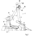
- the measuring device 1 essentially comprises a measuring arm 2 with two articulated arms 3, 4 and a measuring probe 5.
- the articulated arms 3, 4 are connected to one another via bearings, such that axes of rotation II, IV and swivel axes I, III for the measuring device 1 surrender.
- the measuring arm 2 of the device 1 has for the fixed positioning of the individual Working positions of the two articulated arms 3, 4 braking devices K1, K2 and S1 and B2 on. These braking devices are preferably actuated pneumatically.
- a Disc brake device S1 is between a stand 10 and a first one Articulated arm 3 is arranged and consists of a disc element 30 which over opposite sections 30a, 30b is fixed on the articulated arm 3.
- the brake device S1 serves brake pistons 34, 35 which in one brake disk 30 encompassing brake caliper 31 are arranged. With this braking device S1 a Movement about the pivot axis I can be released or blocked.
- first clamping brake device between the stand 10 and the articulated arm 3 K1 arranged.
- This comprises an opposing ring flange 46, 47 of the stand 10 and the first articulated arm 3 overlapping sleeve element 45.
- the adjusting rings 49, 50 spread apart and become over the sleeve element 45 the ring flanges 46, 47 are drawn together by means of a sleeve flange 51.
- the other braking devices K2 and B2 are between the articulated arms 3 and 4 are provided.
- the second clamping brake device K2 essentially comprises one inner sleeve member 36, the foot side with a shoulder part 4 a of the articulated arm 4 connected is.
- An outer sleeve 37 surrounding the sleeve element 36 is only with the Articulated arm 3 connected and includes an annular space 38 for actuators 40, 41, the act against wedge elements 50 with inclined surfaces 39, which correspond to Sloping surfaces 39 of the annulus act.
- the shoe brake device B2 is between the sleeve member 36 and one an approach 36a of the sleeve member 36 attached sleeve part 43 is provided is firmly connected to the articulated arm 4.
- this sleeve part 43 are brake shoes 44a arranged and guided in an annular groove 44.
- the brake shoes 44a are can be pressurized against brake surfaces 44b on sleeve element 36.
Landscapes
- Physics & Mathematics (AREA)
- General Physics & Mathematics (AREA)
- Braking Arrangements (AREA)
Abstract
Description
Es zeigen
- Fig. 1
- eine Seitenansicht auf einen Meßarm mit zwei Gelenkarmen und einem Ständer mit Fußplatte,
- Fig. 2
- eine schaubildliche Darstellung auf eine Scheiben-Bremseinrichtung zwischen Ständer und erstem Gelenkarm,
- Fig. 3
- einen Schnitt durch eine erste Klemm-Bremseinrichtung zwischen Ständer und erstem Gelenkarm,
- Fig. 4
- einen Schnitt durch eine Backen-Bremseinrichtung zwischen erstem und zweitem Gelenkarm, und
- Fig. 5
- einen Schnitt durch eine zweite Klemm-Bremseinrichtung und eine Backen-Bremseinrichtung zwischen erstem und zweitem Gelenkarm.
Claims (8)
- Meßeinrichtung für Baugruppen, insbesondere Karosseriebaugruppen, die einen mehrteiligen Meßarm mit einem Meßtaster aufweist und mit einer Drei-D-Koordinaten speichernden Auswerteeinheit zusammenarbeitet, wobei die Meßeinrichtung aus einem unabhängig von einer stationären Meßplatte verwendbaren Baueinheit mit dem Meßarm besteht, dessen einzelne Gelenkarme verstellbar in Schwenk- und Drehlagen gehalten und über ansteuerbare Einrichtungen in eingestellten Positionen festsetzbar sind, dadurch gekennzeichnet, daß zwischen einem Ständer (10) und einem ersten Gelenkarm (3) eine mit diesem fest verbundene Scheiben-Bremseinrichtung (S1) für eine Schwenkachse (I) und eine erste Klemm-Bremseinrichtung (K1) für eine Drehachse (II) und daß eine Backen-Bremseinrichtung (B2) für eine Schwenkachse (III) sowie eine zweite Klemm-Bremseinrichtung (K2) für eine Drehachse (IV) zwischen dem ersten Gelenkarm (3) und dem zweiten Gelenkarm (4) vorgesehen ist.
- Meßeinrichtung nach Anspruch 1, dadurch gekennzeichnet, daß zwischen dem Ständer (10) und dem ersten Gelenkarm (3) die erste Klemm-Bremseinrichtung (K1) angeordnet ist, welche eine die Flansche (46, 47) des Ständers (10) und des ersten Gelenkarmes (3) übergreifende Hülse (45) aufweist, und zwischen dem Stirnflansch (47) und einem Stützring (48) pneumatisch betätigbare Stellringe (49, 50) vorgeseher sind.
- Meßeinrichtung nach Anspruch 1, dadurch gekennzeichnet, daß die Scheiben-Bremseinrichtung (S1) aus einem mit dem ersten Gelenkarm (3) verbundenen Scheibenelement besteht, das ein die Schwenkachse (I) umgebendes Scheibensegment (30) aufweist und mit am Gelenkarm (3) hochgezogenen und mit diesen fest verbundenen gegenüberstehenden Abschnitten versehen ist.
- Meßeinrichtung nach den Ansprüchen 1 und 3, dadurch gekennzeichnet, daß mit dem Ständer (10) ein Bremssattel (31) für Bremsbacken (32, 33) vorgesehen ist und in denen Bremskolben (34, 35) angeordnet sind, die pneumatisch angesteuert werden.
- Meßeinrichtung nach den Ansprüchen 1, 2, 3 oder 4, dadurch gekennzeichnet, d'ß zwischen dem ersten Gelenkarm (3) und dem zweiten Gelenkarm (4) die zweite Klemm-Bremseinrichtung (K1) und die Backen-Bremseinrichtung (B2) vorgesehen sind, wobei die Klemm-Bremseinrichtung (K2) eine Bewegung um die Drehachse (IV) und die Backen-Bremeinrichtung (B2) eine Bewegung um die Schwenkachse (III) begrenzt bzw. freigibt.
- Meßeinrichtung nach den Ansprüchen 1 oder 5, dadurch gekennzeichnet, daß die Klemm-Bremseinrichtung (K2) zwischen einem den Gelenkarm (3) umgebenden inneren Hülsenelement (36) und einer koaxial hierzu angeordneten äusseren Hülse (37) in einem Ringraum (38) angeordnet ist, der begrenzende, stirnseitige Schrägflächen (39) aufweist, gegen die Stellsegmente (50) mit korrespondierenden Schrägflächen über Stellringe (40, 41) pneumatisch preßbar sind.
- Meßeinrichtung nach den Ansprüchen 1 oder 6, dadurch gekennzeichnet, daß das Hülsenelement (36) mit einem oberen Endbereich (36a) mit einem Ansatzteil (4a) des zweiten Gelenkarmes (4) und die Hülse (37) mit einem unteren Endbereich (42) am Gelenkarm (3) fest verbunden ist und zwischen dem Hülsenelement (36) und der Hülse (37) über die Stellsegmente (40, 41) eine Arretierungs- bzw. Freigabemöglichkeit besteht.
- Meßeinrichtung nach den Ansprüchen 1, 6 oder 7, dadurch gekennzeichnet, daß mit einem Ende des Hülsenelements (36) ein den Gelenkarm (4) umgebendes Hülsenteil (43) verbunden ist, das in einer Ringnut (44) die Backen-Bremseinrichtung (B2) aufnimmt, welche pneumatisch betätigbar ist und aus Bremsbelägen (44a) besteht, die gegen Bremsflächen (44b) des Hülsenelements (36) verstellbar sind.
Applications Claiming Priority (2)
| Application Number | Priority Date | Filing Date | Title |
|---|---|---|---|
| DE19961326 | 1999-12-18 | ||
| DE1999161326 DE19961326C2 (de) | 1998-09-19 | 1999-12-18 | Meßeinrichtung für Baugruppen, insbesondere Karosseriebaugruppen |
Publications (2)
| Publication Number | Publication Date |
|---|---|
| EP1108975A1 true EP1108975A1 (de) | 2001-06-20 |
| EP1108975B1 EP1108975B1 (de) | 2003-09-24 |
Family
ID=7933332
Family Applications (1)
| Application Number | Title | Priority Date | Filing Date |
|---|---|---|---|
| EP00101317A Expired - Lifetime EP1108975B1 (de) | 1999-12-18 | 2000-01-22 | Messeinrichtung für Baugruppen, insbesondere Karosseriebaugruppen |
Country Status (3)
| Country | Link |
|---|---|
| EP (1) | EP1108975B1 (de) |
| DE (1) | DE50003820D1 (de) |
| ES (1) | ES2201957T3 (de) |
Cited By (1)
| Publication number | Priority date | Publication date | Assignee | Title |
|---|---|---|---|---|
| CN105258591A (zh) * | 2015-10-27 | 2016-01-20 | 周凯 | 一种风力发电机多功能调试尺 |
Citations (6)
| Publication number | Priority date | Publication date | Assignee | Title |
|---|---|---|---|---|
| EP0176204A1 (de) * | 1984-09-15 | 1986-04-02 | Lamb-Sceptre Design Centre Limited | Roboterarmgelenk |
| US4664232A (en) * | 1984-04-25 | 1987-05-12 | Bridgestone Corporation | Brake device for robot arm |
| EP0522610A1 (de) * | 1991-06-26 | 1993-01-13 | Sulzer - Escher Wyss AG | Verfahren zur Bestimmung der Flächenkontur von Laufradschaufeln hydraulischer Maschinen, sowie Vorrichtung zur Ausführung des Verfahrens |
| US5293107A (en) * | 1993-02-24 | 1994-03-08 | Fanuc Robotics North America, Inc. | Motorized rotary joint and method of constructing a modular robot utilizing same |
| US5724264A (en) * | 1993-07-16 | 1998-03-03 | Immersion Human Interface Corp. | Method and apparatus for tracking the position and orientation of a stylus and for digitizing a 3-D object |
| DE19648848A1 (de) * | 1996-11-26 | 1998-05-28 | Zett Mess Technik Gmbh | Höhenmeß- und Anreißgerät |
Family Cites Families (1)
| Publication number | Priority date | Publication date | Assignee | Title |
|---|---|---|---|---|
| DE19843052C2 (de) * | 1998-09-19 | 2001-08-16 | Porsche Ag | Meßeinrichtung für Baugruppen, insbesondere Karosseriebaugruppen |
-
2000
- 2000-01-22 ES ES00101317T patent/ES2201957T3/es not_active Expired - Lifetime
- 2000-01-22 EP EP00101317A patent/EP1108975B1/de not_active Expired - Lifetime
- 2000-01-22 DE DE50003820T patent/DE50003820D1/de not_active Expired - Lifetime
Patent Citations (6)
| Publication number | Priority date | Publication date | Assignee | Title |
|---|---|---|---|---|
| US4664232A (en) * | 1984-04-25 | 1987-05-12 | Bridgestone Corporation | Brake device for robot arm |
| EP0176204A1 (de) * | 1984-09-15 | 1986-04-02 | Lamb-Sceptre Design Centre Limited | Roboterarmgelenk |
| EP0522610A1 (de) * | 1991-06-26 | 1993-01-13 | Sulzer - Escher Wyss AG | Verfahren zur Bestimmung der Flächenkontur von Laufradschaufeln hydraulischer Maschinen, sowie Vorrichtung zur Ausführung des Verfahrens |
| US5293107A (en) * | 1993-02-24 | 1994-03-08 | Fanuc Robotics North America, Inc. | Motorized rotary joint and method of constructing a modular robot utilizing same |
| US5724264A (en) * | 1993-07-16 | 1998-03-03 | Immersion Human Interface Corp. | Method and apparatus for tracking the position and orientation of a stylus and for digitizing a 3-D object |
| DE19648848A1 (de) * | 1996-11-26 | 1998-05-28 | Zett Mess Technik Gmbh | Höhenmeß- und Anreißgerät |
Cited By (2)
| Publication number | Priority date | Publication date | Assignee | Title |
|---|---|---|---|---|
| CN105258591A (zh) * | 2015-10-27 | 2016-01-20 | 周凯 | 一种风力发电机多功能调试尺 |
| CN105258591B (zh) * | 2015-10-27 | 2018-06-22 | 周凯 | 一种风力发电机多功能调试尺 |
Also Published As
| Publication number | Publication date |
|---|---|
| DE50003820D1 (de) | 2003-10-30 |
| ES2201957T3 (es) | 2004-04-01 |
| EP1108975B1 (de) | 2003-09-24 |
Similar Documents
| Publication | Publication Date | Title |
|---|---|---|
| DE10112977C1 (de) | Höhenmess- und Anreißgerät | |
| EP0739672B1 (de) | Spannvorrichtung zum umfangsseitigen Spannen von Werkstücken mit beliebiger Umfangskontur | |
| CH708458A2 (de) | Spanneinrichtung. | |
| DE2307537A1 (de) | Bremse mit einem reifenartigen abzubremsenden organ, insbesondere fuer kraftfahrzeuge | |
| DE102011082501A1 (de) | Werkstück-Positioniereinrichtung für eine Werkzeugmaschine und Werkzeugmaschine mit einer derartigen Werkstück-Positioniereinrichtung | |
| EP0127812A1 (de) | Einrichtung zum Befestigen eines Schleifblattes an einem drehbaren Schleifteller eines Schleifgeräts | |
| DE2656210C3 (de) | Bohrstranghalter für Gesteinsbohrgeräte | |
| DE102009007330A1 (de) | Fahrzeugscheibenbremse | |
| DE3346467A1 (de) | Werkzeugmaschine mit werkzeugwechselvorrichtung | |
| EP1108975B1 (de) | Messeinrichtung für Baugruppen, insbesondere Karosseriebaugruppen | |
| EP0987514B1 (de) | Messeinrichtung für Baugruppen, insbesondere Karosseriebaugruppen | |
| EP1142542B1 (de) | Gelenkfräsarm für ein zahntechnisches Fräsgerät | |
| DE19961326C2 (de) | Meßeinrichtung für Baugruppen, insbesondere Karosseriebaugruppen | |
| DE2829152C2 (de) | Verfahren zum radialen Einspannen von Werkstücken mit kegeligen Innenflächen mittels Kraftspannfutter und Kraftspannfutter hierzu | |
| DE69807127T2 (de) | Schleifband Vorrichtung zum Bearbeiten einer cylindrischen Lageroberfläche eines Werkstückes | |
| DE69003943T2 (de) | Verfahren und vorrichtung zur verriegelung von drehkörpern. | |
| DE29816854U1 (de) | Meßeinrichtung für Baugruppen, insbesondere Karosseriebaugruppen | |
| EP0752354A1 (de) | Bremsbetätigungseinrichtung für ein Flurförderfahrzeug | |
| DE1750453B2 (de) | Scheibenbremse, insbesondere für Kraftfahrzeuge | |
| DE102007031336A1 (de) | Feststellbremse für einen Anhänger, sowie Verfahren zum Betrieb einer solchen Feststellbremse | |
| DE2502090C2 (de) | Hydraulische Ringbetätigung für Vollbelagscheibenbremsen, insbesondere für Kraftfahrzeuge | |
| EP1285720B1 (de) | Radialbohrmaschine | |
| DE2424305C3 (de) | Drehmaschine zur Bearbeitung eines Radsatzes von Schienenfahrzeugen | |
| DE1575947C (de) | Scheibenbremse, insbesondere fur Kraftfahrzeuge | |
| DE3924335A1 (de) | Verstelleinrichtung |
Legal Events
| Date | Code | Title | Description |
|---|---|---|---|
| PUAI | Public reference made under article 153(3) epc to a published international application that has entered the european phase |
Free format text: ORIGINAL CODE: 0009012 |
|
| AK | Designated contracting states |
Kind code of ref document: A1 Designated state(s): DE ES FR GB IT SE |
|
| AX | Request for extension of the european patent |
Free format text: AL;LT;LV;MK;RO;SI |
|
| 17P | Request for examination filed |
Effective date: 20011220 |
|
| AKX | Designation fees paid |
Free format text: DE ES FR GB IT SE |
|
| GRAH | Despatch of communication of intention to grant a patent |
Free format text: ORIGINAL CODE: EPIDOS IGRA |
|
| GRAS | Grant fee paid |
Free format text: ORIGINAL CODE: EPIDOSNIGR3 |
|
| GRAA | (expected) grant |
Free format text: ORIGINAL CODE: 0009210 |
|
| AK | Designated contracting states |
Kind code of ref document: B1 Designated state(s): DE ES FR GB IT SE |
|
| REG | Reference to a national code |
Ref country code: GB Ref legal event code: FG4D Free format text: NOT ENGLISH |
|
| REF | Corresponds to: |
Ref document number: 50003820 Country of ref document: DE Date of ref document: 20031030 Kind code of ref document: P |
|
| GBT | Gb: translation of ep patent filed (gb section 77(6)(a)/1977) |
Effective date: 20031009 |
|
| REG | Reference to a national code |
Ref country code: SE Ref legal event code: TRGR |
|
| REG | Reference to a national code |
Ref country code: ES Ref legal event code: FG2A Ref document number: 2201957 Country of ref document: ES Kind code of ref document: T3 |
|
| ET | Fr: translation filed | ||
| PLBE | No opposition filed within time limit |
Free format text: ORIGINAL CODE: 0009261 |
|
| STAA | Information on the status of an ep patent application or granted ep patent |
Free format text: STATUS: NO OPPOSITION FILED WITHIN TIME LIMIT |
|
| 26N | No opposition filed |
Effective date: 20040625 |
|
| REG | Reference to a national code |
Ref country code: FR Ref legal event code: TP |
|
| REG | Reference to a national code |
Ref country code: FR Ref legal event code: CD |
|
| REG | Reference to a national code |
Ref country code: GB Ref legal event code: 732E Free format text: REGISTERED BETWEEN 20100218 AND 20100224 |
|
| REG | Reference to a national code |
Ref country code: FR Ref legal event code: TP |
|
| PGRI | Patent reinstated in contracting state [announced from national office to epo] |
Ref country code: IT Effective date: 20110501 |
|
| REG | Reference to a national code |
Ref country code: DE Ref legal event code: R081 Ref document number: 50003820 Country of ref document: DE Owner name: ZETT MESS TECHNIK GMBH, MESSMASCHINEN, DE Free format text: FORMER OWNER: DR. ING. H.C. F. PORSCHE AKTIENGESELLSCHAFT, 70435 STUTTGART, DE Effective date: 20120702 |
|
| PGFP | Annual fee paid to national office [announced via postgrant information from national office to epo] |
Ref country code: GB Payment date: 20120731 Year of fee payment: 13 Ref country code: SE Payment date: 20120731 Year of fee payment: 13 |
|
| PGFP | Annual fee paid to national office [announced via postgrant information from national office to epo] |
Ref country code: ES Payment date: 20120801 Year of fee payment: 13 Ref country code: FR Payment date: 20120823 Year of fee payment: 13 Ref country code: IT Payment date: 20120731 Year of fee payment: 13 |
|
| PGFP | Annual fee paid to national office [announced via postgrant information from national office to epo] |
Ref country code: DE Payment date: 20130131 Year of fee payment: 14 |
|
| REG | Reference to a national code |
Ref country code: SE Ref legal event code: EUG |
|
| GBPC | Gb: european patent ceased through non-payment of renewal fee |
Effective date: 20130122 |
|
| REG | Reference to a national code |
Ref country code: FR Ref legal event code: ST Effective date: 20130930 |
|
| PG25 | Lapsed in a contracting state [announced via postgrant information from national office to epo] |
Ref country code: SE Free format text: LAPSE BECAUSE OF NON-PAYMENT OF DUE FEES Effective date: 20130123 |
|
| PG25 | Lapsed in a contracting state [announced via postgrant information from national office to epo] |
Ref country code: GB Free format text: LAPSE BECAUSE OF NON-PAYMENT OF DUE FEES Effective date: 20130122 Ref country code: FR Free format text: LAPSE BECAUSE OF NON-PAYMENT OF DUE FEES Effective date: 20130131 |
|
| PG25 | Lapsed in a contracting state [announced via postgrant information from national office to epo] |
Ref country code: IT Free format text: LAPSE BECAUSE OF NON-PAYMENT OF DUE FEES Effective date: 20130122 |
|
| REG | Reference to a national code |
Ref country code: ES Ref legal event code: FD2A Effective date: 20140324 |
|
| PG25 | Lapsed in a contracting state [announced via postgrant information from national office to epo] |
Ref country code: ES Free format text: LAPSE BECAUSE OF NON-PAYMENT OF DUE FEES Effective date: 20130123 |
|
| REG | Reference to a national code |
Ref country code: DE Ref legal event code: R119 Ref document number: 50003820 Country of ref document: DE |
|
| REG | Reference to a national code |
Ref country code: FR Ref legal event code: IC Effective date: 20150311 |
|
| REG | Reference to a national code |
Ref country code: DE Ref legal event code: R119 Ref document number: 50003820 Country of ref document: DE Effective date: 20140801 |
|
| PG25 | Lapsed in a contracting state [announced via postgrant information from national office to epo] |
Ref country code: DE Free format text: LAPSE BECAUSE OF NON-PAYMENT OF DUE FEES Effective date: 20140801 |