EP1108204B1 - Unwuchtmessvorrichtungen mit mindestens einer virtuellen lagerstelle - Google Patents
Unwuchtmessvorrichtungen mit mindestens einer virtuellen lagerstelle Download PDFInfo
- Publication number
- EP1108204B1 EP1108204B1 EP99946065A EP99946065A EP1108204B1 EP 1108204 B1 EP1108204 B1 EP 1108204B1 EP 99946065 A EP99946065 A EP 99946065A EP 99946065 A EP99946065 A EP 99946065A EP 1108204 B1 EP1108204 B1 EP 1108204B1
- Authority
- EP
- European Patent Office
- Prior art keywords
- measuring shaft
- intermediate frame
- measuring
- virtual
- support levers
- Prior art date
- Legal status (The legal status is an assumption and is not a legal conclusion. Google has not performed a legal analysis and makes no representation as to the accuracy of the status listed.)
- Expired - Lifetime
Links
- 238000005259 measurement Methods 0.000 claims description 13
- 238000006073 displacement reaction Methods 0.000 abstract 2
- 238000006243 chemical reaction Methods 0.000 description 5
- 238000003466 welding Methods 0.000 description 4
- 230000035945 sensitivity Effects 0.000 description 3
- 230000032683 aging Effects 0.000 description 2
- 230000005540 biological transmission Effects 0.000 description 2
- 230000000694 effects Effects 0.000 description 2
- 230000035939 shock Effects 0.000 description 2
- 230000003068 static effect Effects 0.000 description 2
- 241000638935 Senecio crassissimus Species 0.000 description 1
- 230000001154 acute effect Effects 0.000 description 1
- 238000005266 casting Methods 0.000 description 1
- 150000001875 compounds Chemical class 0.000 description 1
- 238000010276 construction Methods 0.000 description 1
- 230000003247 decreasing effect Effects 0.000 description 1
- 230000001419 dependent effect Effects 0.000 description 1
- 238000001514 detection method Methods 0.000 description 1
- 238000009434 installation Methods 0.000 description 1
- 239000002184 metal Substances 0.000 description 1
Images


Classifications
-
- G—PHYSICS
- G01—MEASURING; TESTING
- G01M—TESTING STATIC OR DYNAMIC BALANCE OF MACHINES OR STRUCTURES; TESTING OF STRUCTURES OR APPARATUS, NOT OTHERWISE PROVIDED FOR
- G01M1/00—Testing static or dynamic balance of machines or structures
- G01M1/14—Determining imbalance
- G01M1/16—Determining imbalance by oscillating or rotating the body to be tested
- G01M1/28—Determining imbalance by oscillating or rotating the body to be tested with special adaptations for determining imbalance of the body in situ, e.g. of vehicle wheels
Definitions
- the invention relates to devices according to the preamble of claim 1, as known from DE 33 32 978 A1.
- the The measuring shaft is used for balancing motor vehicle wheels in a force transducer bearing on one fixed frame supported.
- To achieve a dynamic Imbalance compensation are two bearing levels, in which also the Force transducers are arranged for the storage of the measuring shaft intended.
- a balancing machine for rotating bodies is known from EP 0 058 860 B1, in which the measuring shaft is rotatably mounted on an elastically flexible flat part arranged vertically on the machine bed.
- the rotary bearing of the measuring shaft is provided on the upper edge of the flat part.
- Position deflections of the flat part are detected by an arm running at a right angle to the flat part by sensors, the force application directions of which are perpendicular to one another.
- One sensor records the static component, while the other sensor detects the forces resulting from the dynamic unbalance, which cause the vertical, resilient flat part to be rotated by approximately a center line.
- DE-AS 16 98 164 is a vibration measuring (Supercritical) measuring system known with a bearing for the Rotor on diagonally placed leaf springs, their Extensions a virtual intersection in one of the Form compensation planes for the rotor to be balanced.
- the two diagonally placed leaf springs are over an intermediate plate arranged parallel to each other vertical leaf springs supported against a base plate. Using vibration transducers, they become one Rotor imbalance resulting vibrations of the leaf springs detected and converted into corresponding measurement signals.
- the in the known devices in the storage levels to the Force transducers provided at the measuring locations provide transducer signals, which are proportional to the centrifugal forces resulting from the rotor unbalance result and in the storage levels or at the measuring locations cause the reaction forces measured by the sensors.
- the conventional standard measuring systems for wheel balancing machines is for the measuring shaft and the one spanned on it Rotor a flying storage usual. Conversion to two compensation levels on the rotor for dynamic unbalance compensation is based on the force-lever laws of statics. The force transducers in the two storage levels measured forces are therefore dependent on the respective distance, which the rotor has to the two force transducers.
- This one Distances are of different sizes, results in the Change the sensitivity of one of the two transducers due to different influences, e.g. by temperature, Aging, shock, overload, transporter vibration, Influence of moisture and the like, a disproportionate Errors in those calculated for the respective compensation levels Leveling compounds.
- the object of the invention is devices of the beginning to create the type mentioned, in which a change in sensitivity a transducer because of the above Force dynamics only marginally on the leveling levels mass balance to be carried out, for example by counterweights to be attached.
- the rigid intermediate frame on which the measuring shaft in a bearing plane having a force transducer is supported on the fixed frame over a supported another force transducer.
- the two force sensors are therefore in two storage systems for a force-measuring Unbalance detection, each force transducer one of the is assigned to both storage systems.
- the two storage systems are between the measuring shaft and the rigid frame, for example the balancing machine on which the unbalance measurement and the unbalance compensation on a motor vehicle wheel is made.
- the force transducers can be however, lie in the area of the rigid intermediate frame Storage levels or in a common storage level.
- At least one further support of the measuring shaft is provided, which is the property of a virtual depository in another storage level.
- There can also be two of these Storage levels with such virtual storage locations are provided his.
- the virtual storage locations can go to both Sides of the rotor to be measured.
- it is also possible, only one that has a virtual storage location provide additional storage level, which is preferred between the two compensation planes of the rotor or also between the plane in which the force transducers are located and the Rotor is located.
- the two force transducers are preferably in one common bearing plane, which is perpendicular to the axis of the measuring shaft runs, arranged.
- the in the force transducers as Reactive forces are parallel, in particular coaxial, aligned and located in the common storage level.
- the force transducers can in the area of the axial extension of the intermediate frame in different storage levels.
- a preferred embodiment is that the measuring shaft in a first bearing level having the force transducer and in a second the virtual base bearing level is supported on the intermediate frame and that the intermediate frame in one storage level over the second force transducer is supported on the fixed frame and also by means of a parallel guide on the stationary frame is articulated.
- the one that has the virtual base Bearing level can be between the rotor, in particular motor vehicle wheel, and the bearing level, which the two force transducers has, or preferably between the two compensation levels of the rotor, in particular motor vehicle wheel.
- the intermediate frame can have a pair of support levers and joints at the respective ends of the support levers on the stationary frame be supported.
- the measuring shaft can also have a pair of support levers and joints are supported on the lever ends on the intermediate frame his.
- the axes of the respective joints run perpendicular to the plane in which the force transducers introduced forces and the axis of the measuring shaft.
- the Support lever pair which the intermediate frame at the fixed Supporting the frame, the parallel guidance of the Effect intermediate frame on the stationary frame. To do this the support levers parallel to each other.
- the Joints of the support levers are then in the corners of a trapezoid the layout of the support levers.
- This arrangement becomes the virtual one located on the outer side of the rotor Camp created.
- the inside of the rotor, in particular virtual lying between the compensation levels Bearing of the measuring shaft on the intermediate frame can also by support levers arranged at an angle to one another Joints in the corners of a trapezoid floor plan of the support lever arrangement lie, be formed.
- the support levers as rigid flat parts, e.g. Sheet metal parts, Castings, rolled flat parts and the like are formed, which together with the joints ensure that in the Measuring sensor the desired one, for example essentially linear and coaxial force transmission.
- the Support lever arrangement which is formed from the flat parts, can be made in one piece, the flat parts are rigid and only the intermediate, essentially linearly flexible joints are.
- the joints can be affected by weak points, for example Constrictions between the individual rigid Flat parts be formed. This makes them flexible Joint axes between the rigid flat parts educated.
- parallel or in Angles then, as explained above, the desired ones virtual storage locations in the respective storage levels form linear bearing axles.
- the virtual storage locations are also those in the frame computer the balancing machine took into account measuring locations, which virtual Represent measurement locations.
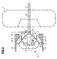
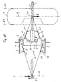
- a schematic representation of a rotor 1 is shown, which is attached to a measuring shaft 2 for measuring unbalance in a known manner by clamping means, not shown.
- the measuring shaft 2 is rotatably mounted on a stationary frame 6. This can be the machine frame of a wheel balancing machine.
- the storage takes place with the help of a storage 3 to be described in detail, which also has force sensors 4, 5.
- the bearing 3 can have a tubular rotary bearing 26 in which the measuring shaft 2 is rotatably mounted.
- the rotary bearing 26, which receives the measuring shaft 2 is rigidly mounted in a first bearing plane 8 on an intermediate frame 7 via the force transducer 4.
- a virtual support point 24 is created in a further bearing plane 9 by support levers 13, 14, which form a pair of support levers and extend at an angle to one another.
- the support point 24 acts like a pivot axis which runs perpendicular to the axis 23 of the measuring shaft 2 and perpendicular to the direction of force introduction of the reaction forces resulting from the unbalance measurement into the force transducer 4.
- the support levers 13 and 14 are articulated (articulations 19 and 22) to the intermediate frame 7 and articulated (articulations 20, 21) to the rotary bearing 26 for the measuring shaft 2.
- the joint axes of the joints 19 to 22 run parallel to the pivot axis, which is formed in the virtual bearing point 24.
- the virtual bearing point 24 can be located between the rotor 1 and the bearing plane 8, in which the force sensors 4 and 5 are located (FIGS. 1 and 2).
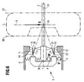
- the virtual bearing point 24 can, however, also be located in the area of the rotor, in particular between balancing planes 27 and 28, in which the unbalance compensation is carried out, for example by applying balancing weights (FIGS. 5 and 6).
- the intermediate frame 7 is fixed on the force transducer 5 Frame 6 supported.
- the force transducer 5 can in the Bearing plane 8 lying perpendicular to the measuring shaft 2 his.
- the intermediate frame 7 is over a pair of support levers (support levers 11 and 12) on the stationary Frame 6 supported. At the ends are the support levers 11, 12 with the fixed frame 6 articulated (joints 15, 16) and articulated (articulations 17, 18 in FIGS. 1, 3, 5, 10 and 7 to 9 and joints 19, 22 in FIGS. 2, 4 and 6) connected to the intermediate frame 7.
- the intermediate frame 7 is as a rigid bearing block or rigid and rigid bearing frame educated.
- the support levers 11 and 12 run essentially parallel to each other and parallel to the axis 23 of the measuring shaft 2. Die Support levers 11 and 12 thus form a parallel link guide to essentially perpendicular to the axis 23 of the measuring shaft 2 directed force transmission during the unbalance measurement run resulting reaction forces in the force transducer 5.
- 4 and 10 are the two support levers 11 and 12 at an acute angle to each other arranged, the apex in the axis 23 of the measuring shaft 2 or in the vicinity of the axis 23.
- This apex forms another virtual bearing 25 in a perpendicular to Measuring shaft 2 extending bearing level 10, which on the Outside of the rotor 1 is.
- FIG. 10 is the virtual Bearing 25 and the storage level 10 in a dash-dotted line drawn extension of the measuring shaft 2, which with respect the bearing 3 of the measuring shaft 2 opposes the longitudinal expansion the measuring shaft 2 runs.
- the bearing 25 and the associated storage level 10 are located with respect to storage 3 on the side opposite to the rotor.
- the virtual depository 25 also has the property of a Swivel axis perpendicular to the axis 23 of the measuring shaft 2 and perpendicular to the direction of the application of force lies in the force transducers 4 and 5. In the illustrated In exemplary embodiments, this force is introduced in the Bearing level 8.
- the hinge axes the joints 15 to 22 parallel to each other and perpendicular to the axis 23 of the measuring shaft 2 and to the direction of force application of the reaction forces in the force transducers 4 and 5 in storage level 8.
- both sides of the rotor 2 namely on the inside and the Outside of the rotor storage levels 9 and 10 with the virtual Bearings 24 and 25 created.
- the virtual storage locations 24 and 25 have the properties of virtual measuring locations.
- the inner bearing 24 associated forces L are from the force transducer 5 and the bearing 25 associated forces R. initiated in the force transducer 4. Generate the force transducers corresponding encoder signals L 'and R'.
- the one virtual bearing point 24, at which a centrifugal force L resulting from the rotor balance can act is located in the bearing plane 9 between the two compensation planes 27, 28, preferably approximately in the middle between the two compensation planes 27, 28.
- the other virtual bearing point 25 is located with respect to the bearing 3 of the measuring shaft 2 on the other side in the extension of the measuring shaft.
- a centrifugal force R resulting from the rotor imbalance acts here.
- the measuring sensors 4 and 5 deliver measuring signals R 'and L' proportional to the centrifugal forces R and L.
- the outer virtual bearing is at infinity or at a relatively large distance of a few meters, for example between about 3 to 20 m and more, because the support levers 11 and 12 essentially one Parallelization of the intermediate frame 7 is effected.
- a centrifugal force resulting from the rotor imbalance (L in FIGS. 1 and 2 and S in FIGS. 5 and 6) is introduced in the bearing level 9 (virtual measuring level) at the virtual bearing point (virtual measuring location), this force becomes only detected by the force transducer 5 and emitted a proportional signal L 'or S'.
- the force transducer 4 emits no signal.
- the force transducer 5 will emit a signal which is only proportional to the centrifugal force magnitude due to the parallel guidance of the intermediate frame 7.
- the force transducer 4 will emit a measurement signal M ', which is not only proportional to the centrifugal force magnitude and thus the unbalance magnitude, but also to the distance of the force introduction point from the bearing level 9 or the virtual bearing point 24.
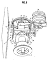
- the intermediate frame 7 is supported on the stationary frame 6 with the aid of the support levers 11 and 12 formed pair of support levers and the support of the tubular rotary bearing 26 of the measuring shaft 2 with the help of the support levers 13 and 14 formed support lever pair in axial direction of the measuring shaft 2 seen one behind the other.
- the Support lever pairs of the embodiments of FIGS. 3 and 4 have the same direction of inclination.
- 12 is the direction of inclination opposite to that Direction of inclination of the pair of support levers 13, 14.
- the support levers 11 to 14 can be formed from flat parts which are rigid and rigid.
- the flat parts can be formed from one piece, the joints being formed by line-shaped weak points, for example in the form of constrictions.
- a holding plate 33 which is part of the holding device 29, can also be formed from the piece which forms the flat parts for the support levers 11 to 14.
- the holding plate 33 is fixedly connected to the tubular rotary bearing 26, for example by welding.
- a support bracket 34 can also be provided as part of the holding device 29, which is also firmly connected to the holding plate 3 and the rotary bearing 26, for example by welding.
- the upper support bracket 34 is shown in the figures. A lower support angle can also be provided.
- the upper and lower support brackets can also consist of an angle piece, in which the rotary bearing 26 is guided through an opening in the angle piece and is firmly connected to the angle piece, for example by welding. This creates a rigid and rigid connection between the holding device 29 and the pivot bearing 26 between the two joints 20 and 21.
- the joints 20 and 21 are located between the two support levers 13 and 14 and the holding plate 33.
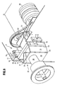
- mounting plates 37, 38 and 40, 41 may be formed from one piece, from which the flat parts for the support levers 11 to 14 are formed.
- the mounting plates 37, 38 are fixed, for example by screw connections or otherwise connected to the fixed frame 6.
- the Fastening plates 37 and 38 form the fastening points for the support lever arm formed from the support levers 11 and 12, with which the intermediate frame 7 on the stationary frame 6 is supported.
- the Vulnerabilities have a concave, especially semicircular Cross-section.
- the two mounting plates are from one piece 40 and 41 formed, which are fixed, for example by Screw connections, welding or the like, with side surfaces of the intermediate frame 7 are connected. Between two mounting plates 40 and 41 and the support levers 11 and 12 are due to the weak points or constrictions Joints 17 and 18 formed. Between the flat parts, which the support levers 13 and 14 are due to weak points or constrictions formed the joints 19 and 22.
- the parallel guidance of the intermediate frame 7 on the stationary Frame results essentially from the fact that the baselines the concave constrictions 15, 17 and 16, 18 to both Sides of the support levers 11 and 12 approximately in parallel planes 35 and 36, in which the leadership function of the two Support lever 11 and 12 is reached.
- the respective constrictions 15, 17 and 16, 18 are on opposite Areas of the support levers 11 and 11 forming the flat parts 12.
- the support levers 11 and 12 are extremely pointed Angle inclined to each other, however, as already explained the parallel steering through leadership function in the parallel planes 35 and 36 is achieved. This can 1 and 5 corresponding measuring arrangements achieved become. To a measuring arrangement corresponding to FIG reach, the support levers 11 and 12 in a corresponding larger angles are inclined to each other.
- FIG 10 Realize the support levers 11, 12 in Figures 7 to 9 towards each other at their rear ends.
- the rear constrictions or joints 15, 16 are closer to Axis of the measuring shaft 2 as the front constrictions or Joints 17, 18.
- the two are Force generator 4, 5 arranged in a line of action, the Force transducer 4 between the pivot bearing 6 and the inside of the intermediate frame 7 and the force transducer 5 between the Outside of the intermediate frame 7 or the mounting plate 41 (Fig. 9) and the fixed frame 6 are arranged.
- An electric motor 30 is provided for driving the measuring shaft 2, which drives the measuring shaft via a belt drive 31.
- the motor 30 is on the pivot bearing 26 via a cantilever arm 32 stored. Through this storage, the measurement result not affected by faults resulting from the motor drive.
Landscapes
- Physics & Mathematics (AREA)
- General Physics & Mathematics (AREA)
- Testing Of Balance (AREA)
- Force Measurement Appropriate To Specific Purposes (AREA)
Applications Claiming Priority (5)
| Application Number | Priority Date | Filing Date | Title |
|---|---|---|---|
| DE19839976 | 1998-09-02 | ||
| DE19839976 | 1998-09-02 | ||
| DE19844975A DE19844975C2 (de) | 1998-09-02 | 1998-09-30 | Vorrichtung zur Messung von Kräften, welche durch eine Unwucht eines Rotors erzeugt werden |
| DE19844975 | 1998-09-30 | ||
| PCT/EP1999/006372 WO2000014503A1 (de) | 1998-09-02 | 1999-08-30 | Vorrichtung zur messung von kräften, welche durch eine unwucht eines rotors erzeugt werden |
Publications (2)
| Publication Number | Publication Date |
|---|---|
| EP1108204A1 EP1108204A1 (de) | 2001-06-20 |
| EP1108204B1 true EP1108204B1 (de) | 2002-03-13 |
Family
ID=26048558
Family Applications (1)
| Application Number | Title | Priority Date | Filing Date |
|---|---|---|---|
| EP99946065A Expired - Lifetime EP1108204B1 (de) | 1998-09-02 | 1999-08-30 | Unwuchtmessvorrichtungen mit mindestens einer virtuellen lagerstelle |
Country Status (17)
| Country | Link |
|---|---|
| US (1) | US6430992B1 (enExample) |
| EP (1) | EP1108204B1 (enExample) |
| JP (1) | JP4344096B2 (enExample) |
| CN (1) | CN1170130C (enExample) |
| AT (1) | ATE214477T1 (enExample) |
| AU (1) | AU751140B2 (enExample) |
| BR (1) | BR9908457B1 (enExample) |
| CA (1) | CA2324315C (enExample) |
| DK (1) | DK1108204T3 (enExample) |
| ES (1) | ES2173000T3 (enExample) |
| HU (1) | HU222970B1 (enExample) |
| NZ (1) | NZ506942A (enExample) |
| PL (1) | PL191114B1 (enExample) |
| RU (1) | RU2245528C2 (enExample) |
| TR (1) | TR200002561T2 (enExample) |
| TW (1) | TW418319B (enExample) |
| WO (1) | WO2000014503A1 (enExample) |
Cited By (3)
| Publication number | Priority date | Publication date | Assignee | Title |
|---|---|---|---|---|
| EP2141474A1 (en) | 2008-07-03 | 2010-01-06 | Snap-on Equipment Srl a unico socio. | Apparatus for measuring forces which are produced by an unbalance of a rotary member |
| EP2196789A1 (en) | 2008-12-10 | 2010-06-16 | Snap-on Equipment Srl a unico socio. | Apparatus for measuring unbalance forces |
| CN101576426B (zh) * | 2008-05-07 | 2012-03-28 | 施耐宝仪器股份有限公司 | 用于测量由车轮的不平衡产生的力的装置 |
Families Citing this family (18)
| Publication number | Priority date | Publication date | Assignee | Title |
|---|---|---|---|---|
| DE10202897B4 (de) * | 2002-01-25 | 2013-04-04 | Snap-On Equipment Gmbh | Vorrichtung und Verfahren zum Messen einer Unwucht eines Motorrad-Rades |
| DE10233917A1 (de) * | 2002-07-25 | 2004-02-12 | Franz Haimer Maschinenbau Kg | Unwucht-Messvorrichtung |
| EP1398610B1 (en) | 2002-09-13 | 2005-05-25 | Snap-on Equipment Srl a unico socio. | Method and apparatus for determining geometrical data of a motor vehicle wheel mounted rotatably about an axis of rotation |
| RU2270985C1 (ru) * | 2004-10-06 | 2006-02-27 | Александр Николаевич Николаев | Способ и устройство для балансировки ротора |
| EP1904975A4 (en) * | 2005-07-12 | 2014-05-14 | Technion Res & Dev Foundation | SYSTEM AND METHOD FOR THE ACTIVE DETECTION OF ASYMMETRY IN ROTATING STRUCTURES |
| FR2909763B1 (fr) * | 2006-12-07 | 2009-01-23 | Renault Sas | Systeme et procede de detection d'un balourd de roue de vehicule automobile |
| RU2426976C2 (ru) * | 2008-05-27 | 2011-08-20 | Александр Николаевич Николаев | Способ и устройство для автоматической балансировки ротора |
| DE102008062255A1 (de) * | 2008-12-15 | 2010-06-17 | Franz Haimer Maschinenbau Kg | Wuchtvorrichtung mit Zusatzlager |
| US8899111B2 (en) * | 2011-03-25 | 2014-12-02 | Snap-On Equipment Srl A Unico Socio | Device for measuring forces generated by an unbalance |
| ES2561221T3 (es) * | 2011-03-25 | 2016-02-25 | Snap-On Equipment Srl A Unico Socio | Dispositivo para medir las fuerzas generadas por un desequilibrio |
| CN103134629B (zh) * | 2011-11-23 | 2015-10-07 | 深圳市福义乐磁性材料有限公司 | 一种测试磁力传动器转子耦合不平衡力的装置及方法 |
| JP5758348B2 (ja) | 2012-06-15 | 2015-08-05 | 住友建機株式会社 | 建設機械の油圧回路 |
| EP2741066B1 (en) | 2012-12-06 | 2019-04-17 | Snap-on Equipment Srl a unico socio | Method of determining rotary angle related data of a vehicle wheel |
| ITMO20120324A1 (it) | 2012-12-21 | 2014-06-22 | Sicam Srl | Macchina equilibratrice per l'equilibratura di ruote di veicoli |
| DE102015224638A1 (de) * | 2015-12-08 | 2017-06-08 | Zf Friedrichshafen Ag | Radkraftdynamometer zur Messung von Reifenkräften |
| CN114646377B (zh) * | 2020-12-21 | 2025-03-04 | 财团法人金属工业研究发展中心 | 振动力量测量装置 |
| IT202100018716A1 (it) | 2021-07-16 | 2023-01-16 | Snap On Equip Srl Unico Socio | Metodo e apparato per determinare le dimensioni geometriche di una ruota di veicoli montata in modo da poter ruotare attorno ad un asse di rotazione |
| CN113790847B (zh) * | 2021-11-16 | 2022-03-11 | 菏泽双龙冶金机械有限公司 | 一种矿山机械零件动平衡检测仪器 |
Family Cites Families (11)
| Publication number | Priority date | Publication date | Assignee | Title |
|---|---|---|---|---|
| AU534527B2 (en) | 1978-05-19 | 1984-02-02 | Sun Electric Corporation | Wheel balancing machine/o/ |
| US4499768A (en) * | 1982-09-08 | 1985-02-19 | Coats Wheel Balancer Corp. | Cantilever support for an apparatus to determine the imbalance in a rotating object |
| US4449407A (en) * | 1982-09-14 | 1984-05-22 | Curchod Donald B | Drive shaft mounting assembly for dynamic wheel balancing machine |
| US4494400A (en) * | 1983-07-28 | 1985-01-22 | Fmc Corporation | Wheel balancer two plane calibration apparatus and method |
| ES2030105T3 (es) * | 1988-05-24 | 1992-10-16 | Schenck-Auto-Service-Gerate Gmbh | Procedimiento para fabricar un apoyo para una maquina equilibradora. |
| US5189912A (en) | 1988-09-07 | 1993-03-02 | Interbalco Ag | Ultrasonic wheel measuring apparatus and wheel balancer incorporating same |
| RU2001380C1 (ru) * | 1991-06-27 | 1993-10-15 | Владимир Тарасович Шведов | Устройство дл измерени дисбаланса тел вращени |
| DE4329831C2 (de) * | 1993-09-03 | 1998-07-23 | Hofmann Werkstatt Technik | Vorrichtung zum Antrieb einer Meßspindel einer Auswuchtmaschine |
| DE4342667C2 (de) * | 1993-12-14 | 1996-04-11 | Hofmann Maschinenbau Gmbh | Vorrichtung zur schwingungsfähigen Abstützung einer Rotorlagerung für einen auszuwuchtenden Rotor in einer Auswuchtmaschine |
| US5847480A (en) * | 1995-11-03 | 1998-12-08 | The Regents Of The University Of California | Passive magnetic bearing element with minimal power losses |
| WO1998010261A1 (en) * | 1996-09-06 | 1998-03-12 | Snap-On Equipment Europe Limited | A wheel balancer |
-
1999
- 1999-08-30 HU HU0101095A patent/HU222970B1/hu not_active IP Right Cessation
- 1999-08-30 PL PL342762A patent/PL191114B1/pl unknown
- 1999-08-30 CA CA002324315A patent/CA2324315C/en not_active Expired - Fee Related
- 1999-08-30 US US09/646,157 patent/US6430992B1/en not_active Expired - Lifetime
- 1999-08-30 AT AT99946065T patent/ATE214477T1/de not_active IP Right Cessation
- 1999-08-30 CN CNB998055867A patent/CN1170130C/zh not_active Expired - Fee Related
- 1999-08-30 AU AU58567/99A patent/AU751140B2/en not_active Ceased
- 1999-08-30 EP EP99946065A patent/EP1108204B1/de not_active Expired - Lifetime
- 1999-08-30 ES ES99946065T patent/ES2173000T3/es not_active Expired - Lifetime
- 1999-08-30 RU RU2000124867/28A patent/RU2245528C2/ru not_active IP Right Cessation
- 1999-08-30 BR BRPI9908457-0A patent/BR9908457B1/pt not_active IP Right Cessation
- 1999-08-30 WO PCT/EP1999/006372 patent/WO2000014503A1/de not_active Ceased
- 1999-08-30 JP JP2000569202A patent/JP4344096B2/ja not_active Expired - Fee Related
- 1999-08-30 DK DK99946065T patent/DK1108204T3/da active
- 1999-08-30 TR TR2000/02561T patent/TR200002561T2/xx unknown
- 1999-08-30 NZ NZ506942A patent/NZ506942A/xx unknown
- 1999-09-01 TW TW088115023A patent/TW418319B/zh not_active IP Right Cessation
Cited By (6)
| Publication number | Priority date | Publication date | Assignee | Title |
|---|---|---|---|---|
| CN101576426B (zh) * | 2008-05-07 | 2012-03-28 | 施耐宝仪器股份有限公司 | 用于测量由车轮的不平衡产生的力的装置 |
| EP2141474A1 (en) | 2008-07-03 | 2010-01-06 | Snap-on Equipment Srl a unico socio. | Apparatus for measuring forces which are produced by an unbalance of a rotary member |
| US8082787B2 (en) | 2008-07-03 | 2011-12-27 | Snap-On Equipment Srl A Unico Socio | Apparatus for measuring forces which are produced by an unbalance of a rotary member |
| CN101620017B (zh) * | 2008-07-03 | 2013-07-24 | 施耐宝仪器股份有限公司 | 用于测量由旋转构件失衡产生的力的设备 |
| EP2196789A1 (en) | 2008-12-10 | 2010-06-16 | Snap-on Equipment Srl a unico socio. | Apparatus for measuring unbalance forces |
| US8671734B2 (en) | 2008-12-10 | 2014-03-18 | Snap-On Equipment Srl A Unico Socio | Apparatus for measuring unbalance forces |
Also Published As
| Publication number | Publication date |
|---|---|
| CN1298484A (zh) | 2001-06-06 |
| PL342762A1 (en) | 2001-07-02 |
| HUP0101095A2 (hu) | 2001-08-28 |
| BR9908457B1 (pt) | 2010-11-30 |
| ES2173000T3 (es) | 2002-10-01 |
| CA2324315C (en) | 2008-11-04 |
| AU751140B2 (en) | 2002-08-08 |
| JP2002524730A (ja) | 2002-08-06 |
| NZ506942A (en) | 2003-04-29 |
| ATE214477T1 (de) | 2002-03-15 |
| EP1108204A1 (de) | 2001-06-20 |
| HUP0101095A3 (en) | 2002-02-28 |
| WO2000014503A1 (de) | 2000-03-16 |
| TW418319B (en) | 2001-01-11 |
| US6430992B1 (en) | 2002-08-13 |
| TR200002561T2 (tr) | 2001-01-22 |
| HU222970B1 (hu) | 2004-01-28 |
| PL191114B1 (pl) | 2006-03-31 |
| BR9908457A (pt) | 2000-11-14 |
| CN1170130C (zh) | 2004-10-06 |
| JP4344096B2 (ja) | 2009-10-14 |
| RU2245528C2 (ru) | 2005-01-27 |
| AU5856799A (en) | 2000-03-27 |
| CA2324315A1 (en) | 2000-03-16 |
| DK1108204T3 (da) | 2002-07-01 |
Similar Documents
| Publication | Publication Date | Title |
|---|---|---|
| EP1108204B1 (de) | Unwuchtmessvorrichtungen mit mindestens einer virtuellen lagerstelle | |
| DE69423341T2 (de) | Reifentestsystem mit konvergierenden lagerungen | |
| DE102013101375B4 (de) | Gelenkwellen-Auswuchtmaschine und Auswuchtverfahren | |
| EP2428788B1 (de) | Vorrichtung zur Drehlagerung eines auszuwuchtenden Rotors | |
| DE69611344T2 (de) | Prüfvorrichtung für ein Rad mit Felge und Reifen mittels Führung des Rades über ein Hindernis | |
| DE2453292C2 (de) | Unterkritisch abgestimmte Auswuchtmaschine | |
| DE19844975C2 (de) | Vorrichtung zur Messung von Kräften, welche durch eine Unwucht eines Rotors erzeugt werden | |
| DE102021123875A1 (de) | Anordnung für einen Lenkgetriebeprüfstand und Lenkgetriebeprüfstand | |
| EP1076231A2 (de) | Einrichtung und Verfahren zur Ermittlung der Unwucht | |
| DD281655A5 (de) | Verfahren und einrichtung zum feststellen und einstellen der lage von laufwerken | |
| DE3716210C2 (enExample) | ||
| EP0010785B1 (de) | Verfahren und Vorrichtung zur Bestimmung der Unwucht eines Rotationskörpers | |
| DE2743393A1 (de) | Auswuchtmaschine | |
| DE2701876C3 (de) | Vorrichtung zum Messen der Unwuchten von Rotoren, insbesondere von Fahrzeugrädern | |
| DE102022207743A1 (de) | Unwuchtmesseinrichtung, Bearbeitungseinrichtung, sowie Verfahren zur Bearbeitung eines Werkstücks | |
| EP4279892A1 (de) | Messvorrichtung zur vermessung von reifen hinsichtlich unwucht und gleichförmigkeit | |
| EP0352788A2 (de) | Messrad | |
| DE10001356A1 (de) | Vorrichtung zur Messung von Kräften, welche durch eine Unwucht eines Rotors erzeugt werden | |
| DE4428758C1 (de) | Vorrichtung zur Ermittlung des Übertragungsverhaltens eines elastischen Lagers | |
| DE102004056367B4 (de) | Lagervorrichtung für eine Vorrichtung zur Ermittlung der Unwucht und der Ungleichförmigkeit eines Rotationskörpers | |
| WO2019219342A1 (de) | Radaufhängung für ein kraftfahrzeug | |
| EP1066426A1 (de) | Bodenverdichtungsmaschine mit mindestens einer walzeneinheit | |
| EP3851355B1 (de) | Portalachse für ein drehgestell eines schienenfahrzeugs | |
| DE2221648C2 (de) | Auswuchtmaschinenlagerung | |
| DE3011110A1 (de) | Stuetzsystem fuer kraftmessende auswuchtmaschinen |
Legal Events
| Date | Code | Title | Description |
|---|---|---|---|
| PUAI | Public reference made under article 153(3) epc to a published international application that has entered the european phase |
Free format text: ORIGINAL CODE: 0009012 |
|
| 17P | Request for examination filed |
Effective date: 20000803 |
|
| AK | Designated contracting states |
Kind code of ref document: A1 Designated state(s): AT BE CH CY DE DK ES FI FR GB GR IE IT LI LU MC NL PT SE |
|
| GRAG | Despatch of communication of intention to grant |
Free format text: ORIGINAL CODE: EPIDOS AGRA |
|
| GRAG | Despatch of communication of intention to grant |
Free format text: ORIGINAL CODE: EPIDOS AGRA |
|
| GRAH | Despatch of communication of intention to grant a patent |
Free format text: ORIGINAL CODE: EPIDOS IGRA |
|
| RTI1 | Title (correction) |
Free format text: ROTOR IMBALANCE MEASURING DEVICES WITH AT LEAST ONE VIRTUAL BEARING POINT |
|
| 17Q | First examination report despatched |
Effective date: 20010809 |
|
| GRAH | Despatch of communication of intention to grant a patent |
Free format text: ORIGINAL CODE: EPIDOS IGRA |
|
| REG | Reference to a national code |
Ref country code: GB Ref legal event code: IF02 |
|
| GRAA | (expected) grant |
Free format text: ORIGINAL CODE: 0009210 |
|
| AK | Designated contracting states |
Kind code of ref document: B1 Designated state(s): AT BE CH CY DE DK ES FI FR GB GR IE IT LI LU MC NL PT SE |
|
| PG25 | Lapsed in a contracting state [announced via postgrant information from national office to epo] |
Ref country code: NL Free format text: LAPSE BECAUSE OF FAILURE TO SUBMIT A TRANSLATION OF THE DESCRIPTION OR TO PAY THE FEE WITHIN THE PRESCRIBED TIME-LIMIT Effective date: 20020313 Ref country code: IE Free format text: LAPSE BECAUSE OF FAILURE TO SUBMIT A TRANSLATION OF THE DESCRIPTION OR TO PAY THE FEE WITHIN THE PRESCRIBED TIME-LIMIT Effective date: 20020313 Ref country code: GR Free format text: LAPSE BECAUSE OF FAILURE TO SUBMIT A TRANSLATION OF THE DESCRIPTION OR TO PAY THE FEE WITHIN THE PRESCRIBED TIME-LIMIT Effective date: 20020313 Ref country code: FI Free format text: LAPSE BECAUSE OF FAILURE TO SUBMIT A TRANSLATION OF THE DESCRIPTION OR TO PAY THE FEE WITHIN THE PRESCRIBED TIME-LIMIT Effective date: 20020313 |
|
| REF | Corresponds to: |
Ref document number: 214477 Country of ref document: AT Date of ref document: 20020315 Kind code of ref document: T |
|
| REG | Reference to a national code |
Ref country code: CH Ref legal event code: EP |
|
| REF | Corresponds to: |
Ref document number: 59900997 Country of ref document: DE Date of ref document: 20020418 |
|
| PG25 | Lapsed in a contracting state [announced via postgrant information from national office to epo] |
Ref country code: PT Free format text: LAPSE BECAUSE OF FAILURE TO SUBMIT A TRANSLATION OF THE DESCRIPTION OR TO PAY THE FEE WITHIN THE PRESCRIBED TIME-LIMIT Effective date: 20020614 |
|
| GBT | Gb: translation of ep patent filed (gb section 77(6)(a)/1977) |
Effective date: 20020523 |
|
| REG | Reference to a national code |
Ref country code: DK Ref legal event code: T3 |
|
| NLV1 | Nl: lapsed or annulled due to failure to fulfill the requirements of art. 29p and 29m of the patents act | ||
| PGFP | Annual fee paid to national office [announced via postgrant information from national office to epo] |
Ref country code: AT Payment date: 20020801 Year of fee payment: 4 |
|
| PGFP | Annual fee paid to national office [announced via postgrant information from national office to epo] |
Ref country code: DK Payment date: 20020805 Year of fee payment: 4 |
|
| PGFP | Annual fee paid to national office [announced via postgrant information from national office to epo] |
Ref country code: MC Payment date: 20020812 Year of fee payment: 4 |
|
| ET | Fr: translation filed | ||
| PGFP | Annual fee paid to national office [announced via postgrant information from national office to epo] |
Ref country code: LU Payment date: 20020826 Year of fee payment: 4 |
|
| PGFP | Annual fee paid to national office [announced via postgrant information from national office to epo] |
Ref country code: IE Payment date: 20020828 Year of fee payment: 4 |
|
| PG25 | Lapsed in a contracting state [announced via postgrant information from national office to epo] |
Ref country code: CY Free format text: LAPSE BECAUSE OF FAILURE TO SUBMIT A TRANSLATION OF THE DESCRIPTION OR TO PAY THE FEE WITHIN THE PRESCRIBED TIME-LIMIT Effective date: 20020831 |
|
| PGFP | Annual fee paid to national office [announced via postgrant information from national office to epo] |
Ref country code: BE Payment date: 20020904 Year of fee payment: 4 |
|
| REG | Reference to a national code |
Ref country code: ES Ref legal event code: FG2A Ref document number: 2173000 Country of ref document: ES Kind code of ref document: T3 |
|
| REG | Reference to a national code |
Ref country code: IE Ref legal event code: FD4D Ref document number: 1108204E Country of ref document: IE |
|
| PLBE | No opposition filed within time limit |
Free format text: ORIGINAL CODE: 0009261 |
|
| STAA | Information on the status of an ep patent application or granted ep patent |
Free format text: STATUS: NO OPPOSITION FILED WITHIN TIME LIMIT |
|
| 26N | No opposition filed |
Effective date: 20021216 |
|
| PG25 | Lapsed in a contracting state [announced via postgrant information from national office to epo] |
Ref country code: LU Free format text: LAPSE BECAUSE OF NON-PAYMENT OF DUE FEES Effective date: 20030830 Ref country code: AT Free format text: LAPSE BECAUSE OF NON-PAYMENT OF DUE FEES Effective date: 20030830 |
|
| PG25 | Lapsed in a contracting state [announced via postgrant information from national office to epo] |
Ref country code: MC Free format text: LAPSE BECAUSE OF NON-PAYMENT OF DUE FEES Effective date: 20030831 Ref country code: LI Free format text: LAPSE BECAUSE OF NON-PAYMENT OF DUE FEES Effective date: 20030831 Ref country code: CH Free format text: LAPSE BECAUSE OF NON-PAYMENT OF DUE FEES Effective date: 20030831 Ref country code: BE Free format text: LAPSE BECAUSE OF NON-PAYMENT OF DUE FEES Effective date: 20030831 |
|
| PG25 | Lapsed in a contracting state [announced via postgrant information from national office to epo] |
Ref country code: DK Free format text: LAPSE BECAUSE OF NON-PAYMENT OF DUE FEES Effective date: 20030901 |
|
| REG | Reference to a national code |
Ref country code: GB Ref legal event code: 732E |
|
| BERE | Be: lapsed |
Owner name: *SNAP-ON TECHNOLOGIES INC. Effective date: 20030831 |
|
| REG | Reference to a national code |
Ref country code: FR Ref legal event code: TP |
|
| REG | Reference to a national code |
Ref country code: DK Ref legal event code: EBP |
|
| REG | Reference to a national code |
Ref country code: CH Ref legal event code: PL |
|
| REG | Reference to a national code |
Ref country code: ES Ref legal event code: PC2A |
|
| PGFP | Annual fee paid to national office [announced via postgrant information from national office to epo] |
Ref country code: SE Payment date: 20040825 Year of fee payment: 6 |
|
| PG25 | Lapsed in a contracting state [announced via postgrant information from national office to epo] |
Ref country code: SE Free format text: LAPSE BECAUSE OF NON-PAYMENT OF DUE FEES Effective date: 20050831 |
|
| EUG | Se: european patent has lapsed | ||
| REG | Reference to a national code |
Ref country code: FR Ref legal event code: PLFP Year of fee payment: 18 |
|
| REG | Reference to a national code |
Ref country code: FR Ref legal event code: PLFP Year of fee payment: 19 |
|
| PGFP | Annual fee paid to national office [announced via postgrant information from national office to epo] |
Ref country code: DE Payment date: 20170904 Year of fee payment: 19 Ref country code: ES Payment date: 20170901 Year of fee payment: 19 Ref country code: IT Payment date: 20170824 Year of fee payment: 19 Ref country code: FR Payment date: 20170823 Year of fee payment: 19 Ref country code: GB Payment date: 20170824 Year of fee payment: 19 |
|
| REG | Reference to a national code |
Ref country code: DE Ref legal event code: R119 Ref document number: 59900997 Country of ref document: DE |
|
| GBPC | Gb: european patent ceased through non-payment of renewal fee |
Effective date: 20180830 |
|
| PG25 | Lapsed in a contracting state [announced via postgrant information from national office to epo] |
Ref country code: IT Free format text: LAPSE BECAUSE OF NON-PAYMENT OF DUE FEES Effective date: 20180830 Ref country code: DE Free format text: LAPSE BECAUSE OF NON-PAYMENT OF DUE FEES Effective date: 20190301 |
|
| PG25 | Lapsed in a contracting state [announced via postgrant information from national office to epo] |
Ref country code: FR Free format text: LAPSE BECAUSE OF NON-PAYMENT OF DUE FEES Effective date: 20180831 |
|
| REG | Reference to a national code |
Ref country code: ES Ref legal event code: FD2A Effective date: 20190918 |
|
| PG25 | Lapsed in a contracting state [announced via postgrant information from national office to epo] |
Ref country code: ES Free format text: LAPSE BECAUSE OF NON-PAYMENT OF DUE FEES Effective date: 20180831 Ref country code: GB Free format text: LAPSE BECAUSE OF NON-PAYMENT OF DUE FEES Effective date: 20180830 |