EP1107447B1 - Elektonisch kommutierter Gleichstrommotor - Google Patents
Elektonisch kommutierter Gleichstrommotor Download PDFInfo
- Publication number
- EP1107447B1 EP1107447B1 EP00123899A EP00123899A EP1107447B1 EP 1107447 B1 EP1107447 B1 EP 1107447B1 EP 00123899 A EP00123899 A EP 00123899A EP 00123899 A EP00123899 A EP 00123899A EP 1107447 B1 EP1107447 B1 EP 1107447B1
- Authority
- EP
- European Patent Office
- Prior art keywords
- motor
- current
- motor according
- winding phase
- rotor
- Prior art date
- Legal status (The legal status is an assumption and is not a legal conclusion. Google has not performed a legal analysis and makes no representation as to the accuracy of the status listed.)
- Expired - Lifetime
Links
- 238000004804 winding Methods 0.000 claims abstract description 52
- 239000004065 semiconductor Substances 0.000 claims abstract description 18
- 238000000034 method Methods 0.000 claims description 3
- 238000007493 shaping process Methods 0.000 claims description 2
- 239000003990 capacitor Substances 0.000 description 19
- 238000011161 development Methods 0.000 description 3
- 230000018109 developmental process Effects 0.000 description 3
- 210000000078 claw Anatomy 0.000 description 2
- 230000001276 controlling effect Effects 0.000 description 2
- 230000008878 coupling Effects 0.000 description 2
- 238000010168 coupling process Methods 0.000 description 2
- 238000005859 coupling reaction Methods 0.000 description 2
- 238000010586 diagram Methods 0.000 description 2
- 238000004519 manufacturing process Methods 0.000 description 2
- 230000003068 static effect Effects 0.000 description 2
- 230000001960 triggered effect Effects 0.000 description 2
- WNEODWDFDXWOLU-QHCPKHFHSA-N 3-[3-(hydroxymethyl)-4-[1-methyl-5-[[5-[(2s)-2-methyl-4-(oxetan-3-yl)piperazin-1-yl]pyridin-2-yl]amino]-6-oxopyridin-3-yl]pyridin-2-yl]-7,7-dimethyl-1,2,6,8-tetrahydrocyclopenta[3,4]pyrrolo[3,5-b]pyrazin-4-one Chemical compound C([C@@H](N(CC1)C=2C=NC(NC=3C(N(C)C=C(C=3)C=3C(=C(N4C(C5=CC=6CC(C)(C)CC=6N5CC4)=O)N=CC=3)CO)=O)=CC=2)C)N1C1COC1 WNEODWDFDXWOLU-QHCPKHFHSA-N 0.000 description 1
- 229910001047 Hard ferrite Inorganic materials 0.000 description 1
- 230000000903 blocking effect Effects 0.000 description 1
- 230000006378 damage Effects 0.000 description 1
- 230000003247 decreasing effect Effects 0.000 description 1
- 230000001419 dependent effect Effects 0.000 description 1
- 230000001939 inductive effect Effects 0.000 description 1
- 239000000203 mixture Substances 0.000 description 1
- 230000001105 regulatory effect Effects 0.000 description 1
- 230000002441 reversible effect Effects 0.000 description 1
- 230000000630 rising effect Effects 0.000 description 1
- 230000002123 temporal effect Effects 0.000 description 1
Images


Classifications
-
- H—ELECTRICITY
- H02—GENERATION; CONVERSION OR DISTRIBUTION OF ELECTRIC POWER
- H02P—CONTROL OR REGULATION OF ELECTRIC MOTORS, ELECTRIC GENERATORS OR DYNAMO-ELECTRIC CONVERTERS; CONTROLLING TRANSFORMERS, REACTORS OR CHOKE COILS
- H02P6/00—Arrangements for controlling synchronous motors or other dynamo-electric motors using electronic commutation dependent on the rotor position; Electronic commutators therefor
- H02P6/20—Arrangements for starting
- H02P6/22—Arrangements for starting in a selected direction of rotation
-
- H—ELECTRICITY
- H02—GENERATION; CONVERSION OR DISTRIBUTION OF ELECTRIC POWER
- H02P—CONTROL OR REGULATION OF ELECTRIC MOTORS, ELECTRIC GENERATORS OR DYNAMO-ELECTRIC CONVERTERS; CONTROLLING TRANSFORMERS, REACTORS OR CHOKE COILS
- H02P6/00—Arrangements for controlling synchronous motors or other dynamo-electric motors using electronic commutation dependent on the rotor position; Electronic commutators therefor
- H02P6/08—Arrangements for controlling the speed or torque of a single motor
Definitions
- the invention relates to an electronically commutated DC motor.
- Such motors are used, inter alia, to drive small fans, cf. the EP-A1-0 908 630 ,
- the document EP-A- 0957570 discloses an electronically commutated motor, with a permanent magnetic rotor and with a stator, which stator has two winding phases, wherein the current is supplied to one winding strand via an associated first semiconductor switch, current is supplied to the other winding strand via an associated second semiconductor switch, and with a commutation device for switching on the first semiconductor switch and the second semiconductor switch.
- this object is achieved by a motor according to claim 1.
- a bistable multivibrator whose switching state is controlled by at least one comparator.
- the comparator is in turn controlled by the voltage induced by the permanent magnet rotor in a currentless current leg.
- a particularly advantageous development of the invention is the subject of claim 23.
- a current limiter which is constantly active to supply the motor with a constant current, surprisingly results in a very advantageous combination, because such a radial fan has a very steep curve so that he can build very high pressures. This represents a valuable security feature, e.g. when a filter in the circuit of the fan is partially blocked.
- the Fig. 1 and 2 show by way of example a radial fan 1, as he from the EP 0 908 630 A1 ( EP-7008 ) is known.
- This has a fan 2 and an electronically commutated external rotor Klauenpolmotor 4, which drives the fan 2 directly.
- the motor 4 has a permanent magnetic outer rotor 6 Fig. 2 two diametrically opposed positioning magnets 8 are provided, which at a standstill of the motor 4, the rotor 6 in a preferred position, also called starting position, turn, from which he can start easily.
- the magnets 8 are arranged in pockets 12 of the fan housing 10.
- the motor 4 has a stator 14 with two opposite Klauenpolblechen 18, 19, between which, as shown, on a bobbin 15, an annular winding 16 is located.
- This is bifilar wound and has two winding strands 25 and 26 with - preferably - same number of turns. These strands are also in Fig. 3 shown. They are inductively coupled by the structure of the motor.
- the strand 25 has two terminals 3A and 3B, which in the Fig. 2 and 3 and strand 26 has two ports 3C and 3D.
- the strand 26 is preferably wound with a thicker wire than the strand 25, which is why the strand 26 has a resistance which is at least 10% lower than the resistance of the strand 25, so that through the strand 26, a higher starting current is possible the strand 25, as in the FIGS. 5 and 6 at 200 is shown.
- the strand 26 has about half the resistance of the strand 25, for example 130 or 260 ⁇ .
- the Klauenpolbleche 18, 19 have claw poles 20 which extend in the axial direction, see. Fig.1 ,
- the rotor magnet is designated 28 and may be a so-called rubber magnet, that is a mixture of rubber and hard ferrite. It is located in a support member 29 which is integrally formed with the fan 2 and in which a shaft 30 is fixed. The latter runs in a radial sliding bearing 32, and its free end is axially supported on a thrust bearing 34.
- the rotor 6 is axially offset from the stator 14 to generate a force F towards the bearing 34.
- the fan 2 has radially extending fan blades 36.
- An axial air intake opening is designated 38.
- an NTC resistor 40 which serves as a temperature sensor and to two terminals K1 and K6 ( Fig. 2 ) connected.
- terminals K1, K6 and 3A to 3D extend in the axial direction down in the form of elongated pins 44, the lower ends 46 can be soldered to a dot-dash line printed circuit board 47, as shown at 49. Further, brackets 48 are provided for mounting the fan 1. With these brackets, the fan may e.g. be attached to the circuit board 47.
- Fans of this type are particularly well suited for use as a so-called printed circuit board fan, ie for direct placement on a circuit board to cool components located there.
- printed circuit board fan ie for direct placement on a circuit board to cool components located there.
- the electronic components E for the operation of such a fan are mounted by the customer on its own circuit board 47, as in Fig. 1 symbolically indicated, and the customer buys only a "naked" fan 1 and mounted this on his circuit board, so that only by this assembly is an operable engine.
- This type of "engine manufacturing” generally prohibits the use of rotor position sensors, such as a Hall generator, as commonly used in electronically commutated motors, to commutate to control.
- the circuit is used in accordance with Fig. 3 , By this starting current, the rotor magnet 28 is rotated in the desired direction in rotation and thereby induces voltages in the two winding strands 25 and 26, and these voltages cause, after a suitable pulse shaping, the commutation of the current through the two winding strands 25 and 26. Man referred that as well as commutation with the induced voltage.
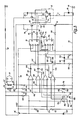
- Fig. 3 shows a circuit diagram according to a preferred embodiment of the invention, which for the electronic commutation of the motor after the Fig. 1 and 2 serves.
- the winding string 25 is connected with its terminal 3A to a positive line 60, which is usually supplied by the (not shown) battery of a vehicle with a voltage between 8 and 16V.
- a negative line 62 is connected via a diode 64 to a negative terminal 66.
- the diode 64 prevents destruction of the fan 1 in case of reverse polarity.
- the terminal 3B of the winding string 25 is connected to the collector of an npn transistor 68.
- the winding string 26 with its terminal 3C to the positive line 60 and with its connection 3D with the collector of an npn transistor 70 connected.
- the emitters of the transistors 68 and 70 are connected to a node 72, and this is connected to the negative line 62 via a common emitter resistor 74.
- an npn transistor 76 Connected in parallel with the resistor 74 is an npn transistor 76, which at start-up switches the resistor 74 for a short time t1 to t2 (FIG. FIGS. 5 and 6 ) bridged, for example, during 0.4 s in order to obtain a high starting current 200 and thereby safe starting of the motor 4. This will be included below FIGS. 5 and 6 described.
- Transistors 68, 70 are associated with a current limiter 78 which limits the current in resistor 74 to a certain value, e.g. to 15 mA.
- the current limiter 78 has two npn transistors 80, 82 whose emitters are connected to the minus line 62 and whose bases are connected to the node 72.
- the collector of the transistor 80 is connected to the base of the transistor 68, the collector of the transistor 82 to the base of the transistor 70.
- a capacitor 84 is connected between the collector and base, the transistor 70, a capacitor 86.
- Transistors 80, 82 are controlled by the voltage drop across emitter resistor 74. As motor current I increases, this voltage drop increases, and thereby transistors 80 and 82 become more conductive, thereby reducing the base current of currently conducting transistor 68 or 70, thereby reducing the current Current l is limited to a desired value corresponding to a desired speed of the fan 1. This stream is e.g. adjustable by changing the resistance 74. By the current limiter 78 is also avoided that flow due to the different resistances of the strands 25, 26 different strand currents, which could cause a turbulent engine running.
- the base of the transistor 68 is connected through a resistor 88 to the output Q of a first, bistable flip-flop 90 whose output Q / is connected via a resistor 92 to the base of the transistor 70.
- a resistor 88 to the output Q of a first, bistable flip-flop 90 whose output Q / is connected via a resistor 92 to the base of the transistor 70.
- the electronic components of the motor 4 are powered by a line 96 with a regulated voltage Vcc of e.g. Supplied 7.5V.
- a control transistor 98 whose base is connected via a Zener diode 100 to the negative line 62, whose collector is connected to the positive line 60, and whose emitter is connected to the line 96.
- the operating voltage on the positive line 60 is transposed by a voltage divider 102, 104 with a terminal 106 in the lower voltage range.
- the voltage at terminal 3B is transposed by a voltage divider 108, 110 with a terminal 112 in the lower voltage range.
- the voltage at terminal 3D is transposed by a voltage divider 114, 116 with a terminal 118 in this lower range.
- Vcc on line 96 is also transposed by a voltage divider 120, 122 with a terminal 124 in this lower range.
- the motor 4 has four comparators 126, 128, 130, 132 connected to the voltage Vcc, which is shown only for the comparator 132.
- first flip-flop 90 and a second flip-flop 134 are connected to the voltage Vcc, which is not shown for reasons of clarity.
- the comparator 126 is connected with its plus input to the node 106 and with its minus input to the node 112. Its output 127 is connected via a capacitor 136 to a node 137 connected directly to the input C of the FF 90, via a resistor 138 to the negative lead 62, and directly to the cathode of a diode 140 whose anode is connected to the negative lead 62.
- the diode 140 becomes conductive when a negative signal occurs at node 137.
- the comparator 128 is also connected with its positive input to the node 106, and with its negative input to the node 118. Its output 142 is connected via a capacitor 144 to the dominant reset input R of the FF 90, further connected via a resistor 146 with a Junction 148, which is connected via a capacitor 150 to the negative line 62 and directly to the negative input of the comparator 130, whose plus input is connected to the node 124. The node 148 is connected to the negative input of the comparator 130, whose positive input is connected to the node 124.
- the output of the comparator 130 is designated 131.
- the reset input R of the FF 90 is connected directly to the cathode of a diode 152, and via a resistor 154 to the negative line 62.
- the anode of the diode 152 is connected to the negative line 62.
- the reset input R of the FF 90 is connected through a resistor 156 to the anode of a diode 158, whose cathode is connected to the output 133 of the comparator 132, the reset input R of the FF 134 and - via a resistor 160 - to the base of the transistor 76 is connected.
- the output 133 is immediately after turning on the motor 4 for a short time at a high potential and blocks the diode 158 during this time.
- the positive input of the comparator 132 is connected to the line 96 (voltage Vcc), the negative input to a node 162 which is connected via a capacitor 164 to the negative line 62 and a resistor 166 to the base of the transistor 98, which in turn via a Resistor 168 is connected to the positive line 60.
- the terminal D of the FF 90 is connected to the line 96, the terminal S of both flip-flops 90, 134 to the negative line 62.
- the terminal C of the FF 134th is connected to the output Q / of the FF 90.
- the output 131 of the comparator 130 is connected to the input D of the FF 134.
- the input R of the FF 134 is connected to the output 133 of the comparator 132.
- the input D of the FF 134 is connected via a switch 172 to a node 174, which is connected via a switch 176 to the output Q of the FF 134 and via a resistor 178 to a terminal 180, where to receive a diagnostic signal in operation, indicating whether the rotor 28 is rotating or stationary. This will be explained below with reference to FIGS. 7 and 8 explained.
- the switches 172, 176 are coupled together as shown, ie either the switch 172 is closed and the switch 176 is open, or vice versa.
- Both strands have the same number of turns and are magnetically coupled.
- the values refer to an engine of the type of claw pole motor shown.
- the voltages on the positive line 60 and on the winding strands 25, 26 are uniformly divided down to values below the voltage Vcc, e.g. in the range 0 ... 7.5 V.
- Vcc voltage below the voltage
- images of the winding voltages and the operating voltage are produced, which images are in the working range of the comparators 126, 128, 130, 132.
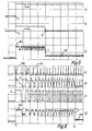
- Fig. 4a with p106 is the potential at point 106 ( Fig. 3 ), with p112 the potential at point 112, which is an image of the voltage on winding line 25, and with p118 the potential at point 118, which is an image of the voltage on winding line 26.
- the comparator 126 With the comparator 126, the zero crossings of the potential p112 are determined, and with the comparator 128, the zero crossings of the potential p118.
- the switching on of one strand also affects the voltage on the other strand, which leads to voltage peaks 190 on the rising positive edge. These parts are therefore unsuitable for controlling the commutation. Rather, the falling edge 192 is measured, and therefore the zero crossing for the control of the commutation at these falling edges 192 is determined.
- Fig. 4b shows the output signal p127 at the output 127 of the comparator 126.
- Fig. 4c shows the output signal p142 at the output 142 of the comparator 128.
- Rectangular signals are obtained there whose phase position runs inversely to the measured potential.
- p127 is inverse to potential p112
- p142 is inverse to potential p118.
- the signal p127 is differentiated, whereby the negative peaks are suppressed by the diode 140. So you get the signals in Fig. 4d ).
- the signal p142 is differentiated, whereby the negative peaks are suppressed by the diode 152. So you get the signals according to Fig. 4e ).
- Fig. 4d the needle pulses according to Fig. 4d) and Fig. 4e ) are converted by the FF 90 into square signals, which in Fig. 4f) and Fig. 4g ) are shown.
- Fig. 4f shows the signal at the output Q of FF 90, and Fig. 4g
- the signal Q controls the transistor 68, the signal Q / the transistor 70.
- the current limiter 78 By the current limiter 78, the current I is limited by the motor during operation, so after the startup phase, to a predetermined value, for example 15 mA.
- a predetermined value for example 15 mA.
- the potential curve p3B is obtained Fig. 4h ), and at point 3D you get the potential curve p3D according to Fig. 4h ).
- the potential on line 60 is shown for comparison, which may be + 16V, for example, when the vehicle battery is fully charged.
- the tension on the strands 25, 26 thus alternates around an average, which in Fig. 4h eg + 16V.
- Fig. 5a shows how the motor 4 is turned on at the time t1, whereby the potential P60 of the positive line 60 jumps from 0 V to 16 V, for example.
- zener diode 100 ( Fig. 3 ) a voltage of, for example, 7.5 V, and through this is charged via the resistor 166 - - previously discharged capacitor 164. This charging lasts approximately 400 ms, namely from t1 to t2, during which time the transistor 76 is held conducting by the output signal of the comparator 132.
- Fig. 5b shows the potential p133 at the output 133 of the comparator 132, which is high between the times t1 and t2 and keeps the transistor 76 conductive.
- Fig. 5c shows the starting motor current I, which has an increased value during this time.
- the ripple of the current I during the no-current-limiting period is a consequence of the winding strands 25 and 26 preferably having different resistances in this motor, and without current limiting, the motor current I is essentially determined by the resistances of the strands 25, 26.
- the motor 28 When switching on the strand 26 must be obtained as a first stream, since then the motor 28 starts from its starting position in the right direction and you get a very high starting current, so a particularly safe start.
- the starting position is generated by the permanent magnets 8, which in Fig. 2 are shown).
- the strand 26 has a resistance of 130 ohms
- the strand 25 has a resistance of 260 ohms, so that a start with the strand 26 results in a higher starting current, which in Fig. 5c ) is clearly visible at 200 from the oscillogram.
- the current limit to 15 mA after time t2 is also clearly visible at 202.
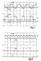
- Fig. 6d shows this current course also, but with greater temporal resolution. There, the same reference numerals are used.
- the flow of the starting current through the string 26 means that the transistor 70 is made conductive by an output signal at the output Q / of the FF 90.
- flip-flops 90 and 134 are used for flip-flops in which one of the inputs is dominant, ie as long as there is a signal at this dominant input R, signals at another input have no influence.
- This dominant input R of the strand 26 is controlled, which must be turned on at the start as the first.
- the other leg 25 is controlled by an input C which is edge-triggered is.
- the signal at the dominant input R is "widened” during startup, so that the dominant state not only acts during the switching process itself, but also somewhat later.
- the output 133 of the comparator 132 goes to a lower potential because the capacitor 164 is now charged, and the diode 158 becomes conductive, switching the resistor 156 in parallel with the resistor 154, thereby correspondingly decreasing the time constant just discussed.
- Fig. 6b shows the pulses at the reset input R of the FF 90, which at start static dominant signal Q / ( Fig. 6c ) at the output Q / of the FF 90 are set high if they have a high value. It can be seen that as a result of the described increased time constant during startup, the signals R (FIG. Fig. 6b ) have a different form between the times t1 and t2 than after the time t2, that is, because of the described change in the time constant after the time t2, these pulses more in the form of needle pulses.
- a fan automatically give a warning when its rotor can not rotate, for example because a mouse has crawled into and blocked the fan.
- the capacitor 150 is provided, which is charged and discharged via the resistor 146 when the motor 4 is running, since then the potential p142 (FIG. Fig. 4c ) at node 142 constantly changes between high and low, so that at node 148 a sawtooth voltage p148 arises, which is alternately larger and smaller than the potential p124 at node 124, which is for example a third of Vcc.
- This results in the output 131 of the comparator 130 is a rectangular signal p131, the in Fig. 7b ) is shown.
- This is supplied to the FF 134, which is connected as a D flip-flop, and there converted into a static high signal, which is available there at the output Q and in Fig. 7c ) is shown.
- This high signal Q is measurable at terminal 180 and indicates that the fan 1 is rotating.
- the circuit acts as an oscillator due to the close inductive coupling of the two strings 25, 26, ie these two strings are now alternately turned off and on at a relatively high frequency. (This frequency is about 2.5 times higher than the frequency reached at operating speed.)
- This condition shows Fig. 8 .
- the potential p148 here also has the form of a sawtooth voltage, but with a higher frequency, and therefore the potential p148 is constantly oscillating by a high value, which is higher than the potential p124, so that with blocked motor no square pulses p131 ( Fig. 7b ) and thus the potential p131 remains low.
- the output Q of the D flip-flop 134 remains low, cf. Fig. 8c ,
- the customer can select how he wants to be informed about the operating state of the engine 4.
- the switches 172, 176 one may provide a fixed connection for the type of display that the customer wishes to have during manufacture. If a microcontroller is used, the type of display may also be programmed.
Landscapes
- Engineering & Computer Science (AREA)
- Power Engineering (AREA)
- Control Of Motors That Do Not Use Commutators (AREA)
- Vending Machines For Individual Products (AREA)
- Dc Machiner (AREA)
Description
- Die Erfindung betrifft einen elektronisch kommutierten Gleichstrommotor. Derartige Motoren werden u.a. zum Antrieb kleiner Lüfter verwendet, vgl. die
EP-A1-0 908 630 . Aus verschiedenen Gründen kann es wünschenswert sein, einen solchen Motor ohne Hallgenerator zu betreiben, also ihn mit der Spannung zu kommutieren, die im Betrieb vom Rotor in der Statorwicklung induziert wird. - Das Dokument
EP-A-0957570 offenbart einen elektronisch kommutierter Motor,
mit einem permanentmagnetischen Rotor und
mit einem Stator, welcher Stator zwei Wicklungsstränge aufweist, wobei dem einen Wicklungsstrang über einen zugeordneten ersten Halbleiterschalter Strom zugeführt wird, dem anderen Wicklungsstrang über einen zugeordneten zweiten Halbleiterschalter Strom zugeführt wird, und
mit einer Kommutierungsvorrichtung zum Einschalten des ersten Halbleiterschalters und des zweiten Halbleiterschalters. - Es ist deshalb eine Aufgabe der Erfindung, einen neuen elektronisch kommutierten Motor bereitzustellen.
- Nach der Erfindung wird diese Aufgabe gelöst durch einen Motor gemäß Patentanspruch 1. Bei der Erfindung verwendet man also zum Steuern des Stromes im Motor einen bistabilen Multivibrator, dessen Schaltzustand über mindestens einen Komparator gesteuert wird. Der Komparator wird seinerseits durch die Spannung gesteuert, die vom permanentmagnetischen Rotor in einem im Augenblick stromlosen Wicklungsstrang induziert wird. Durch den Wegfall eines separaten Rotorstellungssensors hat ein solcher Motor einen einfachen Aufbau bei gutem Wirkungsgrad, da der Stromverbrauch für einen Rotorstellungssensor entfällt. Die Erfindung ist deshalb besonders vorteilhaft für Klein- und Kleinstmotoren, bei denen der Stromverbrauch eines Rotorstellungssensors, z.B. eines Hall-lC, den elektrischen Wirkungsgrad stark reduzieren würde, und sie eignet sich z.B. sehr gut für Motoren, bei denen die elektronischen Komponenten vom eigentlichen Motor (Stator mit Statorwicklung, und Rotor) getrennt angeordnet sind.
- Eine andere Lösung der gestellten Aufgabe, welche einen besonders sicheren Anlauf ergibt, ist Gegenstand des Anspruchs 14. Dabei ergibt sich eine sehr vorteilhafte Weiterbildung durch den Gegenstand des Anspruchs 15, da dann trotz der unterschiedlichen Widerstände der Wicklungsstränge im Betrieb in beiden Wicklungssträngen derselbe Strom fließt, so dass der Motor nicht "hinkt". (Ohne diese Maßnahme würden in den beiden Wicklungssträngen im Betrieb unterschiedlich große Ströme fließen.) Um den Anlauf optimal zu gestalten, wird in bevorzugter Weise diese Strombegrenzung nach dem Einschalten des Motors kurzzeitig deaktiviert, so dass dann der maximale Anlaufstrom durch den niederohmigen Wicklungsstrang bestimmt wird.
- Eine besonders vorteilhafte Weiterbildung der Erfindung ist Gegenstand des Patentanspruchs 23. Besonders in Verbindung mit einem Strombegrenzer, der ständig aktiv ist, um dem Motor einen Konstantstrom zuzuführen, ergibt sich in überraschender Weise eine sehr vorteilhafte Kombination, weil ein solcher Radiallüfter eine sehr steile Kennlinie hat, so dass er besonders hohe Drücke aufbauen kann. Dies stellt ein wertvolles Sicherheitsmerkmal dar, z.B. dann, wenn ein Filter im Kreislauf des Lüfters partiell verstopft ist.
- Weitere Einzelheiten und vorteilhafte Weiterbildungen der Erfindung ergeben sich aus dem im folgenden beschriebenen und in der Zeichnung dargestellten, in keiner Weise als Einschränkung der Erfindung zu verstehenden Ausführungsbeispiel, sowie aus den Unteransprüchen. Es zeigt:
- Fig. 1
- einen Längsschnitt durch einen Lüfter 1, der von einem elektronisch kommutierten Motor 4 angetrieben wird, in stark vergrößerter Darstellung,
- Fig. 2
- eine Draufsicht auf den Lüfter der
Fig. 1 , gesehen in Richtung des Pfeiles II derFig. 1 , - Fig. 3
- ein bevorzugtes Ausführungsbeispiel einer Schaltung zum Betrieb des Motors nach den
Fig. 1 und 2 , - Fig. 4
- eine Darstellung verschiedener Signale, welche in der Schaltung der
Fig. 3 im Betrieb auftreten, - Fig. 5
- eine Darstellung von Signalen, welche beim Start eines Motors nach den
Fig. 1 bis 3 auftreten, - Fig. 6
- eine Darstellung zur Erläuterung der Startkommutierung und der dabei auftretenden Signale,
- Fig. 7
- eine Darstellung welche zeigt, wie bei der Drehung des Motors 4 an einem Signalausgang 180 ein Signal erzeugt wird, welches die Drehung des Motors anzeigt, und
- Fig. 8
- eine Darstellung, welche zeigt, wie bei der Blockierung des Motors 4 am Signalausgang 180 ein Signal erzeugt wird, welches anzeigt, dass sich der Motor nicht dreht.
- Die
Fig. 1 und 2 zeigen beispielhaft einen Radiallüfter 1, wie er aus derEP 0 908 630 A1 (EP-7008 Fig. 2 sind zwei diametral gegenüberliegende Positioniermagnete 8 vorgesehen, welche im Stillstand des Motors 4 den Rotor 6 in eine Vorzugsstellung, auch Startstellung genannt, drehen, aus der er leicht anlaufen kann. Die Magnete 8 sind in Taschen 12 des Lüftergehäuses 10 angeordnet. - Der Motor 4 hat einen Stator 14 mit zwei gegenüberliegenden Klauenpolblechen 18, 19, zwischen welchen sich, wie dargestellt, auf einem Wickelkörper 15 eine ringförmige Wicklung 16 befindet. Diese ist bifilar gewickelt und hat zwei Wicklungsstränge 25 und 26 mit - bevorzugt - gleichen Windungszahlen. Diese Stränge sind auch in
Fig. 3 dargestellt. Sie sind durch den Aufbau des Motors induktiv gekoppelt. - Der Strang 25 hat zwei Anschlüsse 3A und 3B, die in den
Fig. 2 und3 dargestellt sind, und der Strang 26 hat zwei Anschlüsse 3C und 3D. Der Strang 26 ist bevorzugt mit einem dickeren Draht gewickelt als der Strang 25, weshalb der Strang 26 einen Widerstand hat, der um mindestens 10 % niedriger ist als der Widerstand des Stranges 25, so dass durch den Strang 26 ein höherer Anlaufstrom möglich ist als durch den Strang 25, wie das in denFig. 5 und 6 bei 200 dargestellt ist. Bevorzugt hat der Strang 26 etwa die Hälfte des Widerstands des Strangs 25, z.B.130 bzw. 260 Ω. - Die Klauenpolbleche 18, 19 haben Klauenpole 20, die sich in axialer Richtung erstrecken, vgl.
Fig.1 . Der Rotormagnet ist mit 28 bezeichnet und kann ein sogenannter Gummimagnet sein, also eine Mischung aus Gummi und Hartferriten. Er befindet sich in einem Trägerteil 29, das einstückig mit dem Lüfterrad 2 ausgebildet ist und in dem auch eine Welle 30 befestigt ist. Letztere läuft in einem Radial-Gleitlager 32, und ihr freies Ende ist an einem Axiallager 34 axial abgestützt. Der Rotor 6 ist gegenüber dem Stator 14 axial versetzt, um eine Kraft F in Richtung auf das Lager 34 zu erzeugen. - Das Lüfterrad 2 hat radial verlaufende Lüfterflügel 36. Eine axiale Luft-Ansaugöffnung ist mit 38 bezeichnet. In ihr befindet sich ein NTC-Widerstand 40, der als Temperatursensor dient und an zwei Anschlüsse K1 und K6 (
Fig. 2 ) angeschlossen ist. - Die Anschlüsse K1, K6 und 3A bis 3D erstrecken sich in axialer Richtung nach unten in Form von länglichen Stiften 44, deren untere Enden 46 an einer strichpunktiert angedeuteten Leiterplatte 47 festgelötet werden können, wie das bei 49 dargestellt ist. Ferner sind Halterungen 48 für die Befestigung des Lüfters 1 vorgesehen. Mit diesen Halterungen kann der Lüfter z.B. an der Leiterplatte 47 befestigt werden.
- Lüfter dieser Art eignen sich besonders gut zur Verwendung als sogenannte Leiterplattenlüfter, d.h. zur direkten Anordnung auf einer Leiterplatte, um dort befindliche Bauteile zu kühlen. Hinsichtlich weiterer Einzelheiten wird verwiesen auf die
EP 0 908 630 A1 . - Häufig werden die elektronischen Bauelemente E für den Betrieb eines solchen Lüfters vom Kunden auf seiner eigenen Leiterplatte 47 montiert, wie das in
Fig. 1 symbolisch angedeutet ist, und der Kunde kauft sich nur einen "nackten" Lüfter 1 und montiert diesen auf seiner Leiterplatte, so dass erst durch diese Montage ein lauffähiger Motor entsteht. Diese Art der "Motorherstellung" verbietet im allgemeinen die Verwendung von Rotorstellungssensoren, z.B. eines Hallgenerators, wie sie sonst häufig bei elektronisch kommutierten Motoren verwendet werden, um die Kommutierung zu steuern. - Da sich der Rotormagnet 28 beim Start des Motors 4 durch die Wirkung der stationären Magnete 8 in einer vorgegebenen Startstellung, oder in einer aus einer Mehrzahl vorgegebener Startstellungen, befindet, muss beim Einschalten ein vorgegebener Wicklungsstrang der Statorwicklung 16 einen Startstrom in einer vorgegebenen Richtung erhalten. Zum Einschalten dieses Startstroms dient die Schaltung gemäß
Fig. 3 . Durch diesen Startstrom wird der Rotormagnet 28 in der gewünschten Richtung in Umdrehung versetzt und induziert dadurch Spannungen in den beiden Wicklungssträngen 25 und 26, und diese Spannungen bewirken, nach einer geeigneten Impulsformung, die Kommutierung des Stroms durch die beiden Wicklungsstränge 25 und 26. Man bezeichnet das auch als Kommutierung mit der induzierten Spannung. - Selbstverständlich kann statt des Motors nach dem
EP-A1-0 908 630 z.B. ein Motor nach demDE-U1-295 01 695.7 oder demDE-U1-8 702 271.0 verwendet werden. Es handelt sich also bei denFig. 1 und 2 nur um ein bevorzugtes Ausführungsbeispiel, dessen Zweck es ist, ein besseres Verständnis der Erfindung zu ermöglichen, denn ohne ein solches Beispiel wäre die Erfindung möglicherweise schwer verständlich. -
Fig. 3 zeigt ein Schaltbild gemäß einer bevorzugten Ausführungsform der Erfindung, welche zur elektronischen Kommutierung des Motors nach denFig. 1 und 2 dient. - Der Wicklungsstrang 25 ist mit seinem Anschluss 3A an eine Plusleitung 60 angeschlossen, die gewöhnlich von der (nicht dargestellten) Batterie eines Fahrzeugs mit einer Spannung zwischen 8 und 16 V versorgt wird. Eine Minusleitung 62 ist über eine Diode 64 mit einem Minusanschluss 66 verbunden. Die Diode 64 verhindert eine Zerstörung des Lüfters 1 bei Falschpolung. Der Anschluss 3B des Wicklungsstrangs 25 ist mit dem Kollektor eines npn-Transistors 68 verbunden.
- In gleicher Weise ist der Wicklungsstrang 26 mit seinem Anschluss 3C mit der Plusleitung 60 und mit seinem Anschluss 3D mit dem Kollektor eines npn-Transistors 70 verbunden. Die Emitter der Transistoren 68 und 70 sind mit einem Knotenpunkt 72 verbunden, und dieser ist über einen gemeinsamen Emitterwiderstand 74 an die Minusleitung 62 angeschlossen. Parallel zum Widerstand 74 ist ein npn-Transistor 76 geschaltet, der beim Start den Widerstand 74 während einer kurzen Zeit t1 bis t2 (
Fig. 5 und 6 ) überbrückt, z.B. während 0,4 s, um einen hohen Startstrom 200 und dadurch einen sicheren Anlauf des Motors 4 zu erhalten. Dies wird nachfolgend beiFig. 5 und 6 beschrieben. - Den Transistoren 68, 70 ist ein Strombegrenzer 78 zugeordnet, welcher den Strom im Widerstand 74 auf einen bestimmten Wert begrenzt, z.B. auf 15 mA. Der Strombegrenzer 78 hat zwei npn-Transistoren 80, 82, deren Emitter mit der Minusleitung 62 und deren Basen mit dem Knotenpunkt 72 verbunden sind. Der Kollektor des Transistors 80 ist mit der Basis des Transistors 68 verbunden, der Kollektor des Transistors 82 mit der Basis des Transistors 70. Beim Transistor 68 ist ein Kondensator 84 zwischen Kollektor und Basis geschaltet, beim Transistor 70 ein Kondensator 86. Diese sogenannten Millerkondensatoren dienen dazu, die Umschaltvorgänge zu verlangsamen.
- Die Transistoren 80, 82 werden gesteuert vom Spannungsabfall am Emitterwiderstand 74. Wenn der Motorstrom l zunimmt, wird dieser Spannungsabfall größer, und dadurch werden die Transistoren 80 und 82 stärker leitend und reduzieren dadurch den Basisstrom des im Augenblick leitenden Transistors 68 oder 70, wodurch der Strom l auf einen gewünschten Wert begrenzt wird, der einer gewünschten Drehzahl des Lüfters 1 entspricht. Dieser Strom list z.B. einstellbar durch Verändern des Widerstands 74. Durch den Strombegrenzer 78 wird auch vermieden, dass infolge der unterschiedlichen Widerstände der Stränge 25, 26 unterschiedliche Strangströme fließen, was einen unruhigen Motorlauf bewirken könnte.
- Die Basis des Transistors 68 ist über einen Widerstand 88 mit dem Ausgang Q eines ersten, bistabilen Flipflops 90 verbunden, dessen Ausgang Q/ über einen Widerstand 92 mit der Basis des Transistors 70 verbunden ist. Je nach Schaltstellung des Flipflops 90 ist also entweder der Transistor 68 oder der Transistor 70 eingeschaltet, vgl. nachfolgend
Fig. 4f und 4g . - Die elektronischen Bauteile des Motors 4 werden von einer Leitung 96 mit einer geregelten Spannung Vcc von z.B. 7,5 V versorgt. Hierfür dient ein Regeltransistor 98, dessen Basis über eine Zenerdiode 100 mit der Minusleitung 62, dessen Kollektor mit der Plusleitung 60, und dessen Emitter mit der Leitung 96 verbunden ist.
- Damit die verschiedenen Spannungen des Motors im Bereich 0 ... 7,5 V liegen, werden sie durch Spannungsteiler in diesen niedrigeren Spannungsbereich transponiert.
- Die Betriebsspannung an der Plusleitung 60 wird durch einen Spannungsteiler 102, 104 mit einem Anschluss 106 in den niedrigeren Spannungsbereich transponiert.
- Die Spannung am Anschluss 3B wird durch einen Spannungsteiler 108, 110 mit einem Anschluss 112 in den niedrigeren Spannungsbereich transponiert.
- Die Spannung am Anschluss 3D wird durch einen Spannungsteiler 114, 116 mit einem Anschluss 118 in diesen niedrigeren Bereich transponiert.
- Ferner wird auch die Spannung Vcc an der Leitung 96 durch einen Spannungsteiler 120, 122 mit einem Anschluss 124 in diesen niedrigeren Bereich transponiert.
- Der Motor 4 hat vier Komparatoren 126, 128, 130, 132, die an die Spannung Vcc angeschlossen sind, was nur für den Komparator 132 dargestellt ist.
- Auch der erste Flipflop 90 und ein zweiter Flipflop 134 sind an die Spannung Vcc angeschlossen, was aus Gründen der Übersichtlichkeit nicht dargestellt ist.
- Der Komparator 126 ist mit seinem Pluseingang an den Knotenpunkt 106 und mit seinem Minuseingang an den Knotenpunkt 112 angeschlossen. Sein Ausgang 127 ist über einen Kondensator 136 mit einem Knotenpunkt 137 verbunden, der direkt mit dem Eingang C des FF 90, über einen Widerstand 138 mit der Minusleitung 62, und direkt mit der Katode einer Diode 140 verbunden ist, deren Anode an die Minusleitung 62 angeschlossen ist. Die Diode 140 wird leitend, wenn am Knotenpunkt 137 ein negatives Signal auftritt.
- Der Komparator 128 ist mit seinem Pluseingang ebenfalls an den Knotenpunkt 106 angeschlossen, und mit seinem Minuseingang an den Knotenpunkt 118. Sein Ausgang 142 ist über einen Kondensator 144 mit dem dominanten Reset-Eingang R des FF 90 verbunden, ferner über einen Widerstand 146 mit einem Knotenpunkt 148, der über einen Kondensator 150 mit der Minusleitung 62 und direkt mit dem Minuseingang des Komparators 130 verbunden ist, dessen Pluseingang an den Knotenpunkt 124 angeschlossen ist. Der Knotenpunkt 148 ist mit dem Minuseingang des Komparators 130 verbunden, dessen Pluseingang an den Knotenpunkt 124 angeschlossen ist. Der Ausgang des Komparators 130 ist mit 131 bezeichnet.
- Der Reset-Eingang R des FF 90 ist direkt mit der Katode einer Diode 152 verbunden, und über einen Widerstand 154 mit der Minusleitung 62. Die Anode der Diode 152 ist an die Minusleitung 62 angeschlossen. Ferner ist der Reset-Eingang R des FF 90 über einen Widerstand 156 mit der Anode einer Diode 158 verbunden, deren Katode mit dem Ausgang 133 des Komparators 132, dem Reset-Eingang R des FF 134 und - über einen Widerstand 160 - mit der Basis des Transistors 76 verbunden ist. Der Ausgang 133 liegt direkt nach dem Einschalten des Motors 4 kurzzeitig auf einem hohen Potenzial und sperrt während dieser Zeit die Diode 158.
- Der Pluseingang des Komparators 132 ist mit der Leitung 96 (Spannung Vcc) verbunden, der Minuseingang mit einem Knotenpunkt 162, der über einen Kondensator 164 mit der Minusleitung 62 und über einen Widerstand 166 mit der Basis des Transistors 98 verbunden ist, die ihrerseits über einen Widerstand 168 mit der Plusleitung 60 verbunden ist.
- Der Anschluss D des FF 90 ist mit der Leitung 96 verbunden, der Anschluss S beider Flipflops 90, 134 mit der Minusleitung 62. Der Anschluss C des FF 134 ist mit dem Ausgang Q/ des FF 90 verbunden. Der Ausgang 131 des Komparators 130 ist mit dem Eingang D des FF 134 verbunden. Der Eingang R des FF 134 ist mit dem Ausgang 133 des Komparators 132 verbunden. Der Eingang D des FF 134 ist über einen Schalter 172 mit einem Knotenpunkt 174 verbunden, der über einen Schalter 176 mit dem Ausgang Q des FF 134 und über einen Widerstand 178 mit einem Anschluss 180 verbunden ist, an dem man im Betrieb ein Diagnosesignal erhält, das anzeigt, ob der Rotor 28 rotiert oder stillsteht. Dies wird nachfolgend anhand der
Fig. 7 und 8 erläutert. Die Schalter 172, 176 sind in der dargestellten Weise miteinander gekoppelt, d.h. entweder ist der Schalter 172 geschlossen und der Schalter 176 geöffnet, oder umgekehrt. - Motorstrom l im Dauerbetrieb: 15 mA
Strang 25 260 Ω Strang 26 130 Ω - Beide Stränge haben die gleiche Windungszahl und sind magnetisch gekoppelt. Die Werte beziehen sich auf einen Motor vom Typ des dargestellten Klauenpolmotors.
Transistoren 76, 80, 82, 98 BC847BS Transistoren 68, 70 BC817-40 Flipflops 90, 134 MC14013BD Komparatoren 126, 128, 130, 132 LM2902D Zenerdiode 100 BZX284C8V2 Diode 64 BAS216 Dioden140, 152, 158 BAW56S Widerstand 120 68 kΩ Widerstand 122 33 kΩ Widerstände102, 108, 114, 168 47 kΩ Widerstände138, 146, 154, 166 lMΩ Widerstände104, 110, 116, 156 20 kΩ Widerstand 74 39 Ω Widerstände 88, 92,160,178 10 kΩ Kondensator 136 1nF Kondensator 144 22 nF Kondensatoren 84, 86 100 nF Kondensator 164 220 nF Kondensator 150 4,7 nF - Diese Werte sind naturgemäß nur beispielhaft zu verstehen.
- Durch die Spannungsteiler102, 104 bzw. 108, 110 bzw. 114, 116 werden die Spannungen an der Plusleitung 60 und an den Wicklungssträngen 25, 26 gleichmäßig auf Werte herunterdividiert, die unterhalb der Spannung Vcc liegen, also z.B. im Bereich 0 ... 7,5 V. So entstehen Abbildungen der Wicklungsspannungen und der Betriebsspannung, welche Abbildungen sich im Arbeitsbereich der Komparatoren 126, 128, 130, 132 befinden.
- In
Fig. 4a ist mit p106 das Potenzial am Punkt 106 (Fig. 3 ) bezeichnet, mit p112 das Potenzial am Punkt 112, das ein Abbild der Spannung am Wicklungsstrang 25 ist, und mit p118 das Potenzial am Punkt 118, das eine Abbildung der Spannung am Wicklungsstrang 26 ist. - Mit dem Komparator 126 werden die Nulldurchgänge des Potenzials p112 ermittelt, und mit dem Komparator 128 die Nulldurchgänge des Potenzials p118.
- Dabei wird der Umstand ausgenutzt, dass jeweils die positiven Halbwellen der Potenziale p112 und p118 dem stromlosen Zustand des betreffenden Wicklungsstranges 25 bzw. 26 entsprechen, während die negativen Halbwellen entstehen, wenn Strom durch den betreffenden Strang fließt.
- Wegen der engen transformatorischen Kopplung der Stränge 25, 26 wirkt sich das Einschalten eines Stranges auch auf die Spannung am anderen Strang aus, was bei der ansteigenden positiven Flanke zu Spannungsspitzen 190 führt. Diese Teile sind deshalb zur Steuerung der Kommutierung ungeeignet. Gemessen wird vielmehr an der abfallenden Flanke 192, und deshalb wird der Nulldurchgang für die Steuerung der Kommutierung an diesen abfallenden Flanken 192 ermittelt.
-
Fig. 4b ) zeigt das Ausgangssignal p127 am Ausgang 127 des Komparators 126.Fig. 4c zeigt das Ausgangssignal p142 am Ausgang 142 des Komparators 128. - Man erhält dort Rechtecksignale, deren Phasenlage invers zum gemessenen Potenzial verläuft. Z.B. verläuft p127 invers zum Potenzial p112, und p142 verläuft invers zum Potenzial p118.
- Durch den Kondensator 136 und den Widerstand 138 wird das Signal p127 differenziert, wobei durch die Diode 140 die negativen Spitzen unterdrückt werden. Man erhält so die Signale in
Fig. 4d ). Durch den Kondensator 144 und den Widerstand 154 wird das Signal p142 differenziert, wobei durch die Diode 152 die negativen Spitzen unterdrückt werden. So erhält man die Signale gemäßFig. 4e ). - Anschließend werden die Nadelimpulse gemäß
Fig. 4d) und Fig. 4e ) durch den FF 90 in Rechtecksignale umgewandelt, welche inFig. 4f) und Fig. 4g ) dargestellt sind.Fig. 4f ) zeigt das Signal am Ausgang Q des FF 90, undFig. 4g ) zeigt das Signal am Ausgang Q/ des FF 90. Das Signal Q steuert den Transistor 68, das Signal Q/ den Transistor 70. - Durch den Strombegrenzer 78 wird der Strom l durch den Motor im Betrieb, also nach der Startphase, auf einen vorgegebenen Wert begrenzt, z.B. auf 15 mA. Dadurch erhält man am Punkt 3B den Potenzialverlauf p3B gemäß
Fig. 4h ), und am Punkt 3D erhält man den Potenzialverlauf p3D gemäßFig. 4h ). Mit p60 ist das Potenzial an der Leitung 60 zum Vergleich dargestellt, das z.B. + 16 V betragen kann, wenn die Fahrzeugbatterie voll geladen ist. Die Spannung an den Strängen 25, 26 alterniert also um einen Mittelwert, der inFig. 4h z.B. + 16 V beträgt. -
Fig. 5a ) zeigt, wie zum Zeitpunkt t1 der Motor 4 eingeschaltet wird, wodurch das Potenzial p60 der Plusleitung 60 von 0 V auf z.B. 16 V springt. - Hierdurch entsteht an der Zenerdiode 100 (
Fig. 3 ) eine Spannung von z.B. 7,5 V, und durch diese wird über den Widerstand 166 der - zuvor entladene-Kondensator 164 aufgeladen. Diese Aufladung dauert ca. 400 ms, nämlich von t1 bis t2, und während dieser Zeit wird der Transistor 76 durch das Ausgangssignal des Komparators 132 leitend gehalten.Fig. 5b zeigt hierzu das Potenzial p133 am Ausgang 133 des Komparators 132, das zwischen den Zeitpunkten t1 und t2 hoch ist und den Transistor 76 leitend hält.Fig. 5c ) zeigt den Anlauf-Motorstrom l, der während dieser Zeit einen erhöhten Wert hat. (Die Welligkeit des Stromes l während des Zeitraums ohne Strombegrenzung ist eine Folge davon, dass die Wicklungsstränge 25 und 26 bei diesem Motor bevorzugt unterschiedliche Widerstände haben, und ohne Strombegrenzung wird der Motorstrom l im wesentlichen durch die Widerstände der Stränge 25, 26 bestimmt.) - Beim Einschalten muss der Strang 26 als erster Strom erhalten, da dann der Motor 28 aus seiner Startstellung in der richtigen Richtung anläuft und man einen besonders hohen Startstrom, also einen besonders sicheren Start, erhält. (Die Startstellung wird durch die Dauermagnete 8 erzeugt, die in
Fig. 2 dargestellt sind). Beim Ausführungsbeispiel hat der Strang 26 einen Widerstand von 130 Ohm, der Strang 25 einen Widerstand von 260 Ohm, so dass ein Start mit dem Strang 26 einen höheren Startstrom ergibt, was inFig. 5c ) bei 200 aus dem Oszillogramm klar ersichtlich ist. InFig. 5c ) ist bei 202 die Strombegrenzung auf 15 mA nach dem Zeitpunkt t2 ebenfalls klar ersichtlich.Fig. 6d ) zeigt diesen Stromverlauf ebenfalls, aber mit größerer zeitlicher Auflösung. Dort werden dieselben Bezugszeichen verwendet. - Das Fließen des Startstroms durch den Strang 26 bedeutet, dass der Transistor 70 durch ein Ausgangssignal am Ausgang Q/ des FF 90 leitend gesteuert wird. Um dies sicherzustellen, werden für die Flipflops 90 und 134 Flipflops verwendet, bei denen einer der Eingänge dominant ist, d.h. solange an diesem dominanten Eingang R ein Signal liegt, haben Signale an einem anderen Eingang keinen Einfluss. Mit diesem dominanten Eingang R wird der Strang 26 gesteuert, der beim Start als erster eingeschaltet werden muss. Der andere Strang 25 wird von einem Eingang C gesteuert, der flankengetriggert ist.
- Wenn der dominante Eingang R den Strang 26 eingeschaltet hat, könnten Störimpulse am anderen Eingang C eine zu frühe Kommutierung auf den Strang 25 bewirken und dadurch den Anlauf behindern.
- Um das zu verhindern, wird das Signal am dominanten Eingang R während des Anlaufs "verbreitert", so dass der dominante Zustand nicht nur während des Schaltvorgangs selbst wirkt, sondern auch noch etwas danach.
- Nach dem Start wird diese "Impulsverbreiterung" automatisch abgeschaltet.
- Man geht also zur Sicherstellung des Startvorgangs wie folgt vor:
- a) Über den Reset-Eingang R des FF 90 wird der Ausgang Q/ des FF 90 statisch dominant auf einen hohen Wert gesetzt.
- b) Das Rücksetzen des Ausgangs Q/, also das Setzen des Ausgangs Q, erfolgt mittels des Clock-Eingangs C des FF 90, also flankengetriggert.
- c) Der Kondensator 144 (z.B. 22 nF) ist größer als der Kondensator 136 (z.B. 1 nF).
- Zusätzlich wird beim Start durch den positiven Ausgang 133 des Komparators 132 eine andere Zeitkonstante am Reset-Eingang R des FF 90 wirksam, da dann die Diode 158 sperrt, wie bereits erläutert. Beim Start ist deshalb am Reset-Eingang R die Zeitkonstante C144 * R154 wirksam. Diese ist relativ groß und verhindert, dass die in
Fig. 6a ) bei 206 dargestellten Störimpulse des Potenzials p137 am Knotenpunkt 137 den Motor 4 zum Schwingen anregen. - Nach Ablauf der Startphase geht der Ausgang 133 des Komparators 132 auf ein niedrigeres Potenzial, da der Kondensator 164 jetzt geladen ist, und die Diode 158 wird leitend und schaltet den Widerstand 156 parallel zum Widerstand 154, wodurch die eben erläuterte Zeitkonstante entsprechend kleiner wird.
-
Fig. 6b ) zeigt die Impulse am Reset-Eingang R des FF 90, welche beim Start statisch dominant das Signal Q/ (Fig. 6c ) am Ausgang Q/ des FF 90 auf hoch setzen, wenn sie einen hohen Wert haben. Man erkennt, dass durch die beschriebene erhöhte Zeitkonstante beim Anlauf die Signale R (Fig. 6b ) zwischen den Zeitpunkten t1 und t2 eine andere Form haben als nach dem Zeitpunkt t2, d.h. wegen der beschriebenen Änderung der Zeitkonstanten haben nach dem Zeitpunkt t2 diese Impulse mehr die Form von Nadelimpulsen. - Vielfach wird verlangt, dass ein Lüfter automatisch ein Warnsignal abgibt, wenn sich sein Rotor nicht drehen kann, z.B., weil eine Maus in den Lüfter gekrochen ist und diesen blockiert.
- Hierfür ist der Kondensator 150 vorgesehen, welcher über den Widerstand 146 geladen und entladen wird, wenn der Motor 4 läuft, da sich dann das Potenzial p142 (
Fig. 4c ) am Knotenpunkt 142 ständig zwischen hoch und niedrig ändert, so dass am Knotenpunkt 148 eine Sägezahnspannung p148 entsteht, die abwechselnd größer und kleiner ist als das Potenzial p124 am Knotenpunkt 124, das z.B. ein Drittel von Vcc beträgt. Dadurch entsteht am Ausgang 131 des Komparators 130 ein Rechtecksignal p131, das inFig. 7b ) dargestellt ist. Dieses wird dem FF 134 zugeführt, der als D-Flipflop geschaltet ist, und dort in ein statisches High-Signal umgewandelt, das dort am Ausgang Q verfügbar ist und inFig. 7c ) dargestellt ist. Diese hohe Signal Q ist am Anschluss 180 messbar und zeigt an, dass der Lüfter 1 rotiert. - Wenn der Motor 4 blockiert ist, wirkt die Schaltung infolge der engen induktiven Kopplung der beiden Stränge 25, 26 wie ein Oszillator, d.h. diese beiden Stränge werden jetzt abwechselnd mit einer relativ hohen Frequenz aus- und eingeschaltet. (Diese Frequenz ist ca. 2,5 mal höher als die Frequenz, die bei Betriebsdrehzahl erreicht wird.) Diesen Zustand zeigt
Fig. 8 . Das Potenzial p148 hat hier ebenfalls die Form einer Sägezahnspannung, aber mit einer höheren Frequenz, und deshalb oszilliert das Potenzial p148 ständig um einen hohen Wert, der höher ist als das Potenzial p124, so dass bei blockiertem Motor keine Rechteckimpulse p131 (Fig. 7b ) erzeugt werden und folglich das Potenzial p131 niedrig bleibt. Ebenso bleibt der Ausgang Q des D-Flipflops 134 niedrig, vgl.Fig. 8c . - Je nach Stellung der Schalter 172, 176 erhält man also folgende Möglichkeiten:
- a) Bei geschlossenem Schalter 172 erhält man am Ausgang 180 ein Signal entsprechend dem Potenzial p131, also Impulse, wenn der Motor 4 läuft, und keine Impulse, wenn er steht.
- b) Bei geschlossenem Schalter 176 erhält man am Ausgang 180 das Signal Q, das hoch ist, wenn der Motor läuft, und niedrig, wenn der Motor blockiert ist.
- Mittels der Schalter 172, 176 kann der Kunde auswählen, auf welche Weise er über den Betriebszustand des Motors 4 informiert werden möchte. Alternativ kann man statt der Schalter 172, 176 bei der Herstellung eine feste Verbindung für die Art der Anzeige vorsehen, die der Kunde haben möchte. Bei Verwendung eines Mikrocontrollers kann die Art der Anzeige ggf. auch programmiert werden.
Claims (23)
- Elektronisch kommutierter Motor (4),
mit einem permanentmagnetischen Rotor (28) und mit einem Stator (14), welcher Stator zwei Wicklungsstränge (25, 26) aufweist, von denen - während einer Rotordrehung von 360° el. -
zunächst dem einen Wicklungsstrang (25) innerhalb eines ersten Drehwinkelbereichs über einen zugeordneten ersten Halbleiterschalter (68) Strom zugeführt wird und innerhalb eines anschließenden zweiten Drehwinkelbereichs dem anderen Wicklungsstrang (26) über einen zugeordneten zweiten Halbleiterschalter (70) Strom zugeführt wird,
mit einer Kommutierungsvorrichtung zum alternierenden Einschalten des ersten Halbleiterschalters (68) und des zweiten Halbleiterschalters (70), welche einen bistabilen Multivibrator (FF90) aufweist, dessen Schaltzustand über mindestens einen Komparator (126, 128) durch die Spannung gesteuert wird, die vom permanentmagnetischen Rotor (28) in demjenigen im Augenblick stromlosen Wicklungsstrang (25 bzw. 26) induziert wird, der im augenblicklichen Drehwinkelbereich des Rotors (28) nicht über seinen zugeordneten Halbleiterschalter (68 bzw. 70) mit Strom versorgt wird. - Motor nach Anspruch 1, bei welchem der bistabile Multivibrator (FF90) eine elektrische Vorzugsstellung aufweist, die er beim Einschalten einnimmt, um beim Einschaltvorgang die Stromversorgung eines vorgegebenen Wicklungsstranges (26) zu bewirken.
- Motor nach Anspruch 2, bei welchem der Rotor (28) im stromlosen Zustand des Motors (4) eine vorgegebene Stellung einnimmt, aus der er bei Erregung des vorgegebenen Wicklungsstranges (26) in der gewünschten Drehrichtung startet.
- Motor nach einem der Ansprüche 1 bis 3, bei welchem eine in einem stromlosen Wicklungsstrang induzierte Spannung über eine Impulsformerstufe in einen Schaltimpuls (Fig. 4d, 4e) zum Umschalten des bistabilen Multivibrators (FF90) umgeformt wird.
- Motor nach einem oder mehreren der vorhergehenden Ansprüche, bei welchem ein Strombegrenzer (78) vorgesehen ist, welcher den Strom (I) durch die Wicklungsstränge (25, 26) auf einen vorgegebenen Wert begrenzt.
- Motor nach Anspruch 5, bei welchem der Strombegrenzer (78) während einer vorgegebenen Zeitspanne nach dem Einschalten des Motors (4) deaktiviert ist, um einen erhöhten Anlaufstrom (200) zu ermöglichen.
- Motor nach Anspruch 5 oder 6, bei welchem ein Schaltglied (76) vorgesehen ist, welches während einer vorgegebenen Zeitspanne nach dem Einschalten des Motors (4) eingeschaltet wird und dabei den Strombegrenzer (78) überbrückt, um einen hohen Anlaufstrom zu ermöglichen.
- Motor nach einem der Ansprüche 5 bis 7, bei welchem die Halbleiterschalter als Leistungstransistoren (68, 70) ausgebildet sind, und jedem Leistungstransistor ein Transistor (80, 82) zugeordnet ist, welcher bei zunehmendem Motorstrom (I) stärker leitend wird, dabei den Basisstrom des ihm zugeordneten Leistungstransistors (68, 70) reduziert, und so den Motorstrom (I) im wesentlichen konstant hält.
- Motor nach einem oder mehreren der vorhergehenden Ansprüche, bei welchem ein Wicklungsstrang (26) einen um mindestens 10 % niedrigeren ohmschen Widerstand hat als der andere Wicklungsstrang (25).
- Motor nach Anspruch 9, bei welchem die im Betrieb an einem Wicklungsstrang (25, 26) auftretende Spannung (Fig. 4h) in ein im wesentlichen rechteckförmiges Signal (Fig. 4b, 4c) umgeformt wird, und die Umschaltung des bistabilen Multivibrators (FF90) durch eine Flanke dieses Signals gesteuert wird.
- Motor nach einem oder mehreren der vorhergehenden Ansprüche, bei welchem ein Anschluss (180) vorgesehen ist, an welchem bei eingeschaltetem Motor ein Signal abnehmbar ist, dessen Wert davon abhängt, ob sich der Motor dreht oder nicht.
- Motor nach einem oder mehreren der vorhergehenden Ansprüche, bei welchem der Multivibrator (FF90) einen dominanten Eingang (R) aufweist, an welchen beim Einschalten des Motors ein Einschaltsignal gelegt wird, welches das Einschalten eines vorgegebenen Wicklungsstrangs (26) bewirkt.
- Motor nach Anspruch 12, bei welchem der vorgegebene Wicklungsstrang (26), welcher beim Einschalten des Motors bestromt wird, mindestens einer vorgegebenen Drehstellung des Rotors (28) zugeordnet ist, welche dieser im stromlosen Zustand des Motors (4) einnimmt,
um einen Start des Rotors (28) in einer gewünschten Drehrichtung zu bewirken. - Elektronisch kommutierter Motor (4),
mit einem permanentmagnetischen Rotor (26) und mit einem Stator (14), welcher Stator zwei Wicklungsstränge (25,26) aufweist, von denen im Betrieb
- während einer Rotordrehung von 360° el. -
zunächst dem einen Wicklungsstrang (25) innerhalb eines ersten Drehwinkelbereichs über einen zugeordneten ersten Halbleiterschalter (68) Strom zugeführt wird und innerhalb eines anschließenden zweiten Drehwinkelbereichs dem anderen Wicklungsstrang (26) über einen zugeordneten zweiten Halbleiterschalter (70) Strom zugeführt wird,
mit einer Kommutierungsvorrichtung (90) zum alternierenden Einschalten des ersten Halbleiterschalters (68) und des zweiten Halbleiterschalters (70),
wobei sich die ohmschen Widerstände der beiden Wicklungsstränge (25, 26) um mindestens 10 % unterscheiden, so dass ein Wicklungsstrang (25) hochohmig und ein Wicklungsstrang (26) niederohmig ist,
und die Kommutierungsvorrichtung (90) so ausgebildet ist, dass sie beim Einschalten des Motors (4) zuerst den Halbleiterschalter (70) einschaltet, der dem niederohmigen Wicklungsstrang (26) zugeordnet ist. - Motor nach Anspruch 14, bei welchem eine Strombegrenzung (78) vorgesehen ist, welche im Betrieb des Motors (4) den Strom (I) durch die Wicklungsstränge (25, 26) auf einen im wesentlichen identischen Wert begrenzt, der einer gewünschten Drehzahl des Motors zugeordnet ist.
- Motor nach Anspruch 15, bei welchem die Strombegrenzung nach dem Einschalten des Motors kurzzeitig deaktiviert wird, um einen erhöhten Anlaufstrom zu erhalten.
- Motor nach Anspruch 16, bei welchem ein Zeitglied (132, 164, 166) vorgesehen ist, welches durch das Einschalten des Motors aktivierbar ist und während einer vorgegebenen Zeitspanne (Fig. 5: t1 bis t2) die Strombegrenzung (78) deaktiviert.
- Motor nach Anspruch 17, bei welchem das Zeitglied (132, 164, 166) im aktivierten Zustand die Zeitkonstante eines der Kommutierungsvorrichtung (90) zugeordnetem RC-Glieds (144, 154, 156) verändert, um beim Einschalten des Motors (4) als erstes einen Strom durch den niederohmigen Wicklungsstrang (26) zu bewirken, welcher Strom bei deaktivierter Strombegrenzung nicht durch die Strombegrenzung (78) begrenzt ist.
- Motor nach einem der Ansprüche 14 bis 18, welcher einen bistabilen Multivibrator (FF90) aufweist, dessen Schaltzustand durch die Spannung gesteuert wird, die vom permanentmagnetischen Rotor (28) in demjenigen im Augenblick stromlosen Wicklungsstrang (25 bzw. 26) induziert wird, der im augenblicklichen Drehwinkelbereich des Rotors (28) nicht über seinen zugeordneten Halbleiterschalter (68 bzw. 70) mit Strom versorgt wird.
- Motor nach Anspruch 19, bei welchem der Multivibrator (FF90) einen dominanten Eingang (R) aufweist, an welchen beim Einschalten des Motors ein Einschaltsignal gelegt wird, welches das Einschalten des niederohmigen Wicklungsstrangs (26) bewirkt.
- Motor nach einem der Ansprüche 14 bis 20, bei welchem der niederohmige Wicklungsstrang (26), welcher beim Einschalten des Motors bestromt wird, mindestens einer vorgegebenen Drehstellung des Rotors (28) zugeordnet ist, welche dieser im stromlosen Zustand des Motors (4) einnimmt,
um durch Bestromen dieses niederohmigen Wicklungsstranges (26) einen Start des Rotors (28) in einer gewünschten Drehrichtung zu bewirken. - Motor nach einem oder mehreren der vorhergehenden Ansprüche, bei welchem am Stator mindestens ein Dauermagnet (8) vorgesehen ist, um im stromlosen Zustand des Motors den Rotor (14) in eine vorgegebene Drehstellung, oder in eine aus einer Mehrzahl vorgegebener Drehstellungen, zu drehen.
- Motor nach einem oder mehreren der vorhergehenden Ansprüche, welcher mit einem Radiallüfterrad gekoppelt ist.
Applications Claiming Priority (2)
| Application Number | Priority Date | Filing Date | Title |
|---|---|---|---|
| DE29921580U | 1999-12-08 | ||
| DE29921580 | 1999-12-08 |
Publications (3)
| Publication Number | Publication Date |
|---|---|
| EP1107447A2 EP1107447A2 (de) | 2001-06-13 |
| EP1107447A3 EP1107447A3 (de) | 2003-01-22 |
| EP1107447B1 true EP1107447B1 (de) | 2009-12-23 |
Family
ID=8082678
Family Applications (1)
| Application Number | Title | Priority Date | Filing Date |
|---|---|---|---|
| EP00123899A Expired - Lifetime EP1107447B1 (de) | 1999-12-08 | 2000-11-03 | Elektonisch kommutierter Gleichstrommotor |
Country Status (4)
| Country | Link |
|---|---|
| US (1) | US6429615B2 (de) |
| EP (1) | EP1107447B1 (de) |
| AT (1) | ATE453241T1 (de) |
| DE (2) | DE50015828D1 (de) |
Families Citing this family (18)
| Publication number | Priority date | Publication date | Assignee | Title |
|---|---|---|---|---|
| DE59914585D1 (de) * | 1998-12-08 | 2008-01-31 | Ebm Papst St Georgen Gmbh & Co | Elektronisch kommutierter motor |
| JP3928555B2 (ja) * | 2000-10-27 | 2007-06-13 | 三菱電機株式会社 | サーボ制御システム |
| EP1267479A1 (de) * | 2001-06-15 | 2002-12-18 | Saia-Burgess Murten AG | Bürstenloser Gleichstrommotor, Verfahren zum Anlaufen desselben und Verwendung desselben |
| ATE291790T1 (de) * | 2001-08-10 | 2005-04-15 | Ebm Papst St Georgen Gmbh & Co | Verfahren zur steuerung der kommutierung bei einem elektronisch kommutierten motor, und elektronisch kommutierter motor zur durchführung eines solchen verfahrens |
| US7119467B2 (en) * | 2003-03-21 | 2006-10-10 | Pratt & Whitney Canada Corp. | Current limiting means for a generator |
| US6920023B2 (en) * | 2003-03-21 | 2005-07-19 | Pratt & Whitney Canada Corp. | Current limiting means for a generator |
| US7545056B2 (en) * | 2003-05-27 | 2009-06-09 | Pratt & Whitney Canada Corp. | Saturation control of electric machine |
| US7583063B2 (en) | 2003-05-27 | 2009-09-01 | Pratt & Whitney Canada Corp. | Architecture for electric machine |
| US7262539B2 (en) * | 2004-11-26 | 2007-08-28 | Pratt & Whitney Canada Corp. | Saturation control of electric machine |
| US6965183B2 (en) * | 2003-05-27 | 2005-11-15 | Pratt & Whitney Canada Corp. | Architecture for electric machine |
| US7253548B2 (en) | 2003-06-16 | 2007-08-07 | Pratt & Whitney Canada Corp. | Method and apparatus for controlling an electric machine |
| US7573217B2 (en) | 2005-05-31 | 2009-08-11 | Regal-Beloit Corporation | Methods and systems for automatic rotation direction determination of electronically commutated motor |
| US7288923B1 (en) | 2006-04-21 | 2007-10-30 | Pratt & Whitney Canada Corp. | Voltage-limited electric machine |
| US7439713B2 (en) * | 2006-09-20 | 2008-10-21 | Pratt & Whitney Canada Corp. | Modulation control of power generation system |
| US8076882B2 (en) * | 2007-12-26 | 2011-12-13 | Pratt & Whitney Canada Corp. | Motor drive architecture with active snubber |
| USD703301S1 (en) | 2011-08-08 | 2014-04-22 | Ebm-Papst St. Georgen Gmbh & Co. Kg | Axial fan |
| TWI686540B (zh) * | 2019-02-01 | 2020-03-01 | 建準電機工業股份有限公司 | 具連接座之風扇 |
| DE102021110687A1 (de) * | 2021-04-27 | 2022-10-27 | Bühler Motor GmbH | Verfahren zum Anlaufen eines Rotors eines Klauenpolmotors |
Family Cites Families (22)
| Publication number | Priority date | Publication date | Assignee | Title |
|---|---|---|---|---|
| DE2311398A1 (de) * | 1973-03-08 | 1974-09-12 | Kienzle Apparate Gmbh | Schaltungsanordnung fuer den betrieb eines wenigstens zwei statorspulen aufweisenden synchronmotors |
| US3801887A (en) * | 1973-04-10 | 1974-04-02 | Amf Inc | Brushless variable speed drive for a. c. synchronous motor |
| DE2339077A1 (de) | 1973-08-02 | 1975-02-13 | Helmut Dr Ing Moczala | Gleichstromkleinstmotor mit dauermagnetlaeufer |
| US4459519A (en) * | 1974-06-24 | 1984-07-10 | General Electric Company | Electronically commutated motor systems and control therefor |
| US4162435A (en) * | 1976-10-05 | 1979-07-24 | General Electric Company | Method and apparatus for electronically commutating a direct current motor without position sensors |
| US4156168A (en) | 1976-11-03 | 1979-05-22 | Tokheim Corporation | Electric motor |
| IT1093284B (it) * | 1977-02-11 | 1985-07-19 | Cableform Ltd | Perfezionamenti relativi ai controlli d'impulso |
| US4275343A (en) * | 1978-12-28 | 1981-06-23 | The Charles Stark Draper Laboratory, Inc. | Back EMF controlled permanent magnet motor |
| US4459532A (en) * | 1982-07-29 | 1984-07-10 | Eaton Corporation | H-Switch start-up control for AC motor |
| GB8304714D0 (en) * | 1983-02-21 | 1983-03-23 | Ass Elect Ind | Induction motors |
| US4868479A (en) * | 1985-10-15 | 1989-09-19 | The Charles Stark Draper Laboratory, Inc. | Low loss permanent magnet motor |
| DE8702271U1 (de) | 1987-02-14 | 1987-06-04 | Papst-Motoren GmbH & Co KG, 7742 St Georgen | Kollektorloser Gleichstrommotor mit permanentmagnetischem Rotor |
| JP2875529B2 (ja) | 1987-10-31 | 1999-03-31 | ソニー株式会社 | センサレスブラシレスモータの駆動装置 |
| DE9416084U1 (de) * | 1993-10-25 | 1995-02-23 | Papst-Motoren GmbH & Co. KG, 78112 St Georgen | Netzgerät |
| EP0666424B1 (de) | 1994-02-05 | 1997-10-15 | PAPST-MOTOREN GmbH & Co. KG | Lüfter mit einem Lüfterrad |
| JPH08512453A (ja) | 1994-02-09 | 1996-12-24 | フィリップス エレクトロニクス ネムローゼ フェンノートシャップ | ブラシレス直流モータ |
| DE4438569C2 (de) | 1994-10-28 | 1998-09-24 | Bosch Gmbh Robert | Verfahren und Schaltungsanordnung zum Anfahren eines elektronisch kommutierten Gleichstrommotors |
| DE19518991A1 (de) * | 1994-11-21 | 1997-01-23 | Papst Motoren Gmbh & Co Kg | Verfahren zum Betrieb eines elektronisch kommutierten Motors, und Motor zur Durchführung eines solchen Verfahrens |
| ATE190775T1 (de) | 1995-09-29 | 2000-04-15 | Papst Motoren Gmbh & Co Kg | Elektronisch kommutierter aussenläufermotor |
| DE29718082U1 (de) | 1997-10-11 | 1999-02-11 | Papst Motoren Gmbh & Co Kg | Kleinlüftereinheit, insbesondere zur Verwendung als Leiterplattenlüfter |
| DE19820929A1 (de) * | 1998-05-09 | 1999-11-11 | Ako Werke Gmbh & Co | Vorrichtung zum Steuern eines Einphasen-Synchronmotors |
| DE19826458A1 (de) | 1998-06-13 | 1999-12-16 | Papst Motoren Gmbh & Co Kg | Anordnung mit einem Elektromotor |
-
2000
- 2000-11-03 AT AT00123899T patent/ATE453241T1/de not_active IP Right Cessation
- 2000-11-03 EP EP00123899A patent/EP1107447B1/de not_active Expired - Lifetime
- 2000-11-03 DE DE50015828T patent/DE50015828D1/de not_active Expired - Lifetime
- 2000-11-16 DE DE20019449U patent/DE20019449U1/de not_active Expired - Lifetime
- 2000-12-04 US US09/729,377 patent/US6429615B2/en not_active Expired - Fee Related
Also Published As
| Publication number | Publication date |
|---|---|
| EP1107447A3 (de) | 2003-01-22 |
| US6429615B2 (en) | 2002-08-06 |
| EP1107447A2 (de) | 2001-06-13 |
| ATE453241T1 (de) | 2010-01-15 |
| US20010004194A1 (en) | 2001-06-21 |
| DE20019449U1 (de) | 2001-01-11 |
| DE50015828D1 (de) | 2010-02-04 |
Similar Documents
| Publication | Publication Date | Title |
|---|---|---|
| EP1107447B1 (de) | Elektonisch kommutierter Gleichstrommotor | |
| EP0150324B1 (de) | Kollektorloser Gleichstrommotor | |
| EP1314894B1 (de) | Lüfter | |
| EP1104950B1 (de) | Elektronisch kommutierter Gleichstrommotor | |
| DE3044056C2 (de) | Zweipulsiger kollektorloser Gleichstrommotor | |
| EP1839388B1 (de) | Steuerschatung für einen elektronisch kommutierten motor | |
| EP0084156B1 (de) | Kollektorloser Gleichstrommotor | |
| DE68914841T2 (de) | Elektrischer motor. | |
| EP0766370B1 (de) | Elektronisch kommutierter Aussenläufermotor | |
| DE3526007C2 (de) | Schaltungsanordnung zum Ansteuern eines kollektorlosen, an ein Gleichstromnetz angeschlossenen Gleichsstrommotors | |
| EP1107441A2 (de) | Elektronisch kommunierter Gleichstrommotor | |
| DE2618293C2 (de) | ||
| DE2031141A1 (de) | Kommutator-Motor mit einem Dauermagnetläufer | |
| DE2461391C3 (de) | Drehzahlregelschaltung für einen kollektorlosen Gleichstrommotor | |
| DE8702271U1 (de) | Kollektorloser Gleichstrommotor mit permanentmagnetischem Rotor | |
| DE2321022C2 (de) | Kollektorloser Gleichstrommotor mit einem axialen Luftspalt | |
| DE4323504B4 (de) | Schaltung zur Bestromung eines bürstenlosen Gleichstrommotors | |
| DE2314259A1 (de) | Kollektorloser gleichstrommotor | |
| DE3804549C2 (de) | Kleingebläse mit einem Ventilatorlaufrad | |
| EP1142100B1 (de) | Elektronisch kommutierter motor | |
| DE2463006C2 (de) | Zweipulsiger kollektorloser Gleichstrommotor | |
| DE2012571C3 (de) | Kollektorloser Gleichstrommotor | |
| DE2616044A1 (de) | Kollektorloser gleichstrommotor | |
| DE2625596C2 (de) | ||
| DE3628306A1 (de) | Schaltungsanordnung zur ansteuerung eines kollektorlosen gleichstrommotors |
Legal Events
| Date | Code | Title | Description |
|---|---|---|---|
| PUAI | Public reference made under article 153(3) epc to a published international application that has entered the european phase |
Free format text: ORIGINAL CODE: 0009012 |
|
| AK | Designated contracting states |
Kind code of ref document: A2 Designated state(s): AT BE CH CY DE DK ES FI FR GB GR IE IT LI LU MC NL PT SE TR |
|
| AX | Request for extension of the european patent |
Free format text: AL;LT;LV;MK;RO;SI |
|
| PUAL | Search report despatched |
Free format text: ORIGINAL CODE: 0009013 |
|
| AK | Designated contracting states |
Kind code of ref document: A3 Designated state(s): AT BE CH CY DE DK ES FI FR GB GR IE IT LI LU MC NL PT SE TR |
|
| AX | Request for extension of the european patent |
Free format text: AL;LT;LV;MK;RO;SI |
|
| RIC1 | Information provided on ipc code assigned before grant |
Free format text: 7H 02P 6/18 A, 7H 02P 6/22 B |
|
| 17P | Request for examination filed |
Effective date: 20030110 |
|
| AKX | Designation fees paid |
Designated state(s): AT BE CH CY DE DK ES FI FR GB GR IE IT LI LU MC NL PT SE TR |
|
| GRAP | Despatch of communication of intention to grant a patent |
Free format text: ORIGINAL CODE: EPIDOSNIGR1 |
|
| GRAS | Grant fee paid |
Free format text: ORIGINAL CODE: EPIDOSNIGR3 |
|
| RAP1 | Party data changed (applicant data changed or rights of an application transferred) |
Owner name: EBM-PAPST ST. GEORGEN GMBH & CO. KG |
|
| GRAA | (expected) grant |
Free format text: ORIGINAL CODE: 0009210 |
|
| AK | Designated contracting states |
Kind code of ref document: B1 Designated state(s): AT BE CH CY DE DK ES FI FR GB GR IE IT LI LU MC NL PT SE TR |
|
| REG | Reference to a national code |
Ref country code: GB Ref legal event code: FG4D Free format text: NOT ENGLISH |
|
| REG | Reference to a national code |
Ref country code: CH Ref legal event code: EP |
|
| REG | Reference to a national code |
Ref country code: IE Ref legal event code: FG4D |
|
| REF | Corresponds to: |
Ref document number: 50015828 Country of ref document: DE Date of ref document: 20100204 Kind code of ref document: P |
|
| REG | Reference to a national code |
Ref country code: NL Ref legal event code: VDEP Effective date: 20091223 |
|
| PG25 | Lapsed in a contracting state [announced via postgrant information from national office to epo] |
Ref country code: SE Free format text: LAPSE BECAUSE OF FAILURE TO SUBMIT A TRANSLATION OF THE DESCRIPTION OR TO PAY THE FEE WITHIN THE PRESCRIBED TIME-LIMIT Effective date: 20091223 Ref country code: FI Free format text: LAPSE BECAUSE OF FAILURE TO SUBMIT A TRANSLATION OF THE DESCRIPTION OR TO PAY THE FEE WITHIN THE PRESCRIBED TIME-LIMIT Effective date: 20091223 |
|
| REG | Reference to a national code |
Ref country code: IE Ref legal event code: FD4D |
|
| PG25 | Lapsed in a contracting state [announced via postgrant information from national office to epo] |
Ref country code: ES Free format text: LAPSE BECAUSE OF FAILURE TO SUBMIT A TRANSLATION OF THE DESCRIPTION OR TO PAY THE FEE WITHIN THE PRESCRIBED TIME-LIMIT Effective date: 20100403 Ref country code: NL Free format text: LAPSE BECAUSE OF FAILURE TO SUBMIT A TRANSLATION OF THE DESCRIPTION OR TO PAY THE FEE WITHIN THE PRESCRIBED TIME-LIMIT Effective date: 20091223 Ref country code: PT Free format text: LAPSE BECAUSE OF FAILURE TO SUBMIT A TRANSLATION OF THE DESCRIPTION OR TO PAY THE FEE WITHIN THE PRESCRIBED TIME-LIMIT Effective date: 20100423 |
|
| PG25 | Lapsed in a contracting state [announced via postgrant information from national office to epo] |
Ref country code: CY Free format text: LAPSE BECAUSE OF FAILURE TO SUBMIT A TRANSLATION OF THE DESCRIPTION OR TO PAY THE FEE WITHIN THE PRESCRIBED TIME-LIMIT Effective date: 20091223 Ref country code: GR Free format text: LAPSE BECAUSE OF FAILURE TO SUBMIT A TRANSLATION OF THE DESCRIPTION OR TO PAY THE FEE WITHIN THE PRESCRIBED TIME-LIMIT Effective date: 20100324 Ref country code: IE Free format text: LAPSE BECAUSE OF FAILURE TO SUBMIT A TRANSLATION OF THE DESCRIPTION OR TO PAY THE FEE WITHIN THE PRESCRIBED TIME-LIMIT Effective date: 20091223 |
|
| PLBE | No opposition filed within time limit |
Free format text: ORIGINAL CODE: 0009261 |
|
| STAA | Information on the status of an ep patent application or granted ep patent |
Free format text: STATUS: NO OPPOSITION FILED WITHIN TIME LIMIT |
|
| PGFP | Annual fee paid to national office [announced via postgrant information from national office to epo] |
Ref country code: IT Payment date: 20100728 Year of fee payment: 11 |
|
| 26N | No opposition filed |
Effective date: 20100924 |
|
| PG25 | Lapsed in a contracting state [announced via postgrant information from national office to epo] |
Ref country code: DK Free format text: LAPSE BECAUSE OF FAILURE TO SUBMIT A TRANSLATION OF THE DESCRIPTION OR TO PAY THE FEE WITHIN THE PRESCRIBED TIME-LIMIT Effective date: 20091223 |
|
| BERE | Be: lapsed |
Owner name: EBM-PAPST ST. GEORGEN G.M.B.H. & CO. KG Effective date: 20101130 |
|
| PG25 | Lapsed in a contracting state [announced via postgrant information from national office to epo] |
Ref country code: MC Free format text: LAPSE BECAUSE OF NON-PAYMENT OF DUE FEES Effective date: 20101130 |
|
| REG | Reference to a national code |
Ref country code: CH Ref legal event code: PL |
|
| GBPC | Gb: european patent ceased through non-payment of renewal fee |
Effective date: 20101103 |
|
| PG25 | Lapsed in a contracting state [announced via postgrant information from national office to epo] |
Ref country code: LI Free format text: LAPSE BECAUSE OF NON-PAYMENT OF DUE FEES Effective date: 20101130 Ref country code: CH Free format text: LAPSE BECAUSE OF NON-PAYMENT OF DUE FEES Effective date: 20101130 |
|
| PG25 | Lapsed in a contracting state [announced via postgrant information from national office to epo] |
Ref country code: BE Free format text: LAPSE BECAUSE OF NON-PAYMENT OF DUE FEES Effective date: 20101130 |
|
| REG | Reference to a national code |
Ref country code: DE Ref legal event code: R119 Ref document number: 50015828 Country of ref document: DE Effective date: 20110601 Ref country code: DE Ref legal event code: R119 Ref document number: 50015828 Country of ref document: DE Effective date: 20110531 |
|
| PG25 | Lapsed in a contracting state [announced via postgrant information from national office to epo] |
Ref country code: DE Free format text: LAPSE BECAUSE OF NON-PAYMENT OF DUE FEES Effective date: 20110531 |
|
| PG25 | Lapsed in a contracting state [announced via postgrant information from national office to epo] |
Ref country code: GB Free format text: LAPSE BECAUSE OF NON-PAYMENT OF DUE FEES Effective date: 20101103 |
|
| PGFP | Annual fee paid to national office [announced via postgrant information from national office to epo] |
Ref country code: FR Payment date: 20111003 Year of fee payment: 12 |
|
| REG | Reference to a national code |
Ref country code: AT Ref legal event code: MM01 Ref document number: 453241 Country of ref document: AT Kind code of ref document: T Effective date: 20101103 |
|
| PG25 | Lapsed in a contracting state [announced via postgrant information from national office to epo] |
Ref country code: AT Free format text: LAPSE BECAUSE OF NON-PAYMENT OF DUE FEES Effective date: 20101103 |
|
| PG25 | Lapsed in a contracting state [announced via postgrant information from national office to epo] |
Ref country code: IT Free format text: LAPSE BECAUSE OF NON-PAYMENT OF DUE FEES Effective date: 20111103 |
|
| PG25 | Lapsed in a contracting state [announced via postgrant information from national office to epo] |
Ref country code: LU Free format text: LAPSE BECAUSE OF NON-PAYMENT OF DUE FEES Effective date: 20101103 |
|
| PG25 | Lapsed in a contracting state [announced via postgrant information from national office to epo] |
Ref country code: TR Free format text: LAPSE BECAUSE OF FAILURE TO SUBMIT A TRANSLATION OF THE DESCRIPTION OR TO PAY THE FEE WITHIN THE PRESCRIBED TIME-LIMIT Effective date: 20091223 |
|
| REG | Reference to a national code |
Ref country code: FR Ref legal event code: ST Effective date: 20130731 |
|
| PG25 | Lapsed in a contracting state [announced via postgrant information from national office to epo] |
Ref country code: FR Free format text: LAPSE BECAUSE OF NON-PAYMENT OF DUE FEES Effective date: 20121130 |