EP0908630A1 - Kleinlüftereinheit, insbesondere zur Verwendung als Leiterplattenlüfter - Google Patents
Kleinlüftereinheit, insbesondere zur Verwendung als Leiterplattenlüfter Download PDFInfo
- Publication number
- EP0908630A1 EP0908630A1 EP98114778A EP98114778A EP0908630A1 EP 0908630 A1 EP0908630 A1 EP 0908630A1 EP 98114778 A EP98114778 A EP 98114778A EP 98114778 A EP98114778 A EP 98114778A EP 0908630 A1 EP0908630 A1 EP 0908630A1
- Authority
- EP
- European Patent Office
- Prior art keywords
- fan unit
- rotor
- unit according
- small fan
- stator
- Prior art date
- Legal status (The legal status is an assumption and is not a legal conclusion. Google has not performed a legal analysis and makes no representation as to the accuracy of the status listed.)
- Granted
Links
Images


Classifications
-
- H—ELECTRICITY
- H02—GENERATION; CONVERSION OR DISTRIBUTION OF ELECTRIC POWER
- H02K—DYNAMO-ELECTRIC MACHINES
- H02K5/00—Casings; Enclosures; Supports
- H02K5/04—Casings or enclosures characterised by the shape, form or construction thereof
- H02K5/22—Auxiliary parts of casings not covered by groups H02K5/06-H02K5/20, e.g. shaped to form connection boxes or terminal boxes
- H02K5/225—Terminal boxes or connection arrangements
-
- F—MECHANICAL ENGINEERING; LIGHTING; HEATING; WEAPONS; BLASTING
- F04—POSITIVE - DISPLACEMENT MACHINES FOR LIQUIDS; PUMPS FOR LIQUIDS OR ELASTIC FLUIDS
- F04D—NON-POSITIVE-DISPLACEMENT PUMPS
- F04D25/00—Pumping installations or systems
- F04D25/02—Units comprising pumps and their driving means
- F04D25/06—Units comprising pumps and their driving means the pump being electrically driven
- F04D25/0606—Units comprising pumps and their driving means the pump being electrically driven the electric motor being specially adapted for integration in the pump
- F04D25/0613—Units comprising pumps and their driving means the pump being electrically driven the electric motor being specially adapted for integration in the pump the electric motor being of the inside-out type, i.e. the rotor is arranged radially outside a central stator
- F04D25/064—Details of the rotor
-
- F—MECHANICAL ENGINEERING; LIGHTING; HEATING; WEAPONS; BLASTING
- F04—POSITIVE - DISPLACEMENT MACHINES FOR LIQUIDS; PUMPS FOR LIQUIDS OR ELASTIC FLUIDS
- F04D—NON-POSITIVE-DISPLACEMENT PUMPS
- F04D25/00—Pumping installations or systems
- F04D25/02—Units comprising pumps and their driving means
- F04D25/06—Units comprising pumps and their driving means the pump being electrically driven
- F04D25/0606—Units comprising pumps and their driving means the pump being electrically driven the electric motor being specially adapted for integration in the pump
- F04D25/0613—Units comprising pumps and their driving means the pump being electrically driven the electric motor being specially adapted for integration in the pump the electric motor being of the inside-out type, i.e. the rotor is arranged radially outside a central stator
- F04D25/0646—Details of the stator
-
- F—MECHANICAL ENGINEERING; LIGHTING; HEATING; WEAPONS; BLASTING
- F04—POSITIVE - DISPLACEMENT MACHINES FOR LIQUIDS; PUMPS FOR LIQUIDS OR ELASTIC FLUIDS
- F04D—NON-POSITIVE-DISPLACEMENT PUMPS
- F04D25/00—Pumping installations or systems
- F04D25/02—Units comprising pumps and their driving means
- F04D25/06—Units comprising pumps and their driving means the pump being electrically driven
- F04D25/0606—Units comprising pumps and their driving means the pump being electrically driven the electric motor being specially adapted for integration in the pump
- F04D25/0666—Units comprising pumps and their driving means the pump being electrically driven the electric motor being specially adapted for integration in the pump a sensor is integrated into the pump/motor design
-
- H—ELECTRICITY
- H02—GENERATION; CONVERSION OR DISTRIBUTION OF ELECTRIC POWER
- H02K—DYNAMO-ELECTRIC MACHINES
- H02K29/00—Motors or generators having non-mechanical commutating devices, e.g. discharge tubes or semiconductor devices
- H02K29/03—Motors or generators having non-mechanical commutating devices, e.g. discharge tubes or semiconductor devices with a magnetic circuit specially adapted for avoiding torque ripples or self-starting problems
-
- H—ELECTRICITY
- H02—GENERATION; CONVERSION OR DISTRIBUTION OF ELECTRIC POWER
- H02K—DYNAMO-ELECTRIC MACHINES
- H02K29/00—Motors or generators having non-mechanical commutating devices, e.g. discharge tubes or semiconductor devices
- H02K29/06—Motors or generators having non-mechanical commutating devices, e.g. discharge tubes or semiconductor devices with position sensing devices
- H02K29/12—Motors or generators having non-mechanical commutating devices, e.g. discharge tubes or semiconductor devices with position sensing devices using detecting coils using the machine windings as detecting coil
-
- H—ELECTRICITY
- H02—GENERATION; CONVERSION OR DISTRIBUTION OF ELECTRIC POWER
- H02K—DYNAMO-ELECTRIC MACHINES
- H02K3/00—Details of windings
- H02K3/46—Fastening of windings on the stator or rotor structure
- H02K3/52—Fastening salient pole windings or connections thereto
- H02K3/521—Fastening salient pole windings or connections thereto applicable to stators only
- H02K3/525—Annular coils, e.g. for cores of the claw-pole type
-
- H—ELECTRICITY
- H02—GENERATION; CONVERSION OR DISTRIBUTION OF ELECTRIC POWER
- H02K—DYNAMO-ELECTRIC MACHINES
- H02K5/00—Casings; Enclosures; Supports
- H02K5/04—Casings or enclosures characterised by the shape, form or construction thereof
- H02K5/16—Means for supporting bearings, e.g. insulating supports or means for fitting bearings in the bearing-shields
- H02K5/167—Means for supporting bearings, e.g. insulating supports or means for fitting bearings in the bearing-shields using sliding-contact or spherical cap bearings
- H02K5/1675—Means for supporting bearings, e.g. insulating supports or means for fitting bearings in the bearing-shields using sliding-contact or spherical cap bearings radially supporting the rotary shaft at only one end of the rotor
-
- H—ELECTRICITY
- H02—GENERATION; CONVERSION OR DISTRIBUTION OF ELECTRIC POWER
- H02K—DYNAMO-ELECTRIC MACHINES
- H02K2211/00—Specific aspects not provided for in the other groups of this subclass relating to measuring or protective devices or electric components
- H02K2211/03—Machines characterised by circuit boards, e.g. pcb
-
- H—ELECTRICITY
- H02—GENERATION; CONVERSION OR DISTRIBUTION OF ELECTRIC POWER
- H02K—DYNAMO-ELECTRIC MACHINES
- H02K5/00—Casings; Enclosures; Supports
Definitions
- the present invention relates to a small fan unit with a fan wheel and a collectorless one that drives it DC motor, especially for direct placement on a circuit board.
- Such a fan unit is for example from the German utility model 295 01 695.7 known. It is the drive motor as a disc motor with an annular disc Permanent magnet rotor formed. Of the Rotor is axially offset from and parallel to the stator arranged so that between the permanent magnet rotor and a coaxial stator toroid has a flat air gap is formed.
- the stator has an annular, ferromagnetic Sheet metal disc as a magnetic yoke element for the rotor magnet.
- Another ferromagnetic Yoke disk can be attached in the rotor itself.
- the present invention is based on the object to create a small fan of the generic type, the is particularly simple, compact and inexpensive.
- the DC motor as a single-phase, single-stranded claw-pole motor formed with a permanent magnet rotor without inference is, wherein at least one is a start position of the Positioning magnet effecting the rotor is provided.
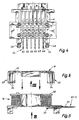
- the stator has one toroidal coaxial with the axis of rotation and two axially opposite Claw pole plates, each with two in particular Claw poles on.
- the claw poles each extend starting from the associated claw pole plate in axial Direction so that they lie radially next to the ring coil.
- the Claw pole plates are mutually such in the circumferential direction offset that the claw poles of the two sheets in Alternate circumferential direction. This will form the Claw poles in the circumferential direction of neighboring north and south poles.
- the ring coil is bifilar wound and has one Working winding and a sensor winding (speedometer winding) on.
- the rotor magnet in the sensor winding induced rotor position dependent signals.
- the working circuit signals through the control circuit controlled with one pulse, i.e. alternately switched on and off. There is therefore deliberately no alternating magnetic field generated, for which a full-bridge control is required would.
- the control circuit is thereby extraordinary inexpensive; at most it costs as much as a Hall IC.
- the claw pole motor according to the invention can be compared to a disc rotor of the same performance more compact, in particular with a smaller outside diameter.
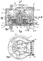
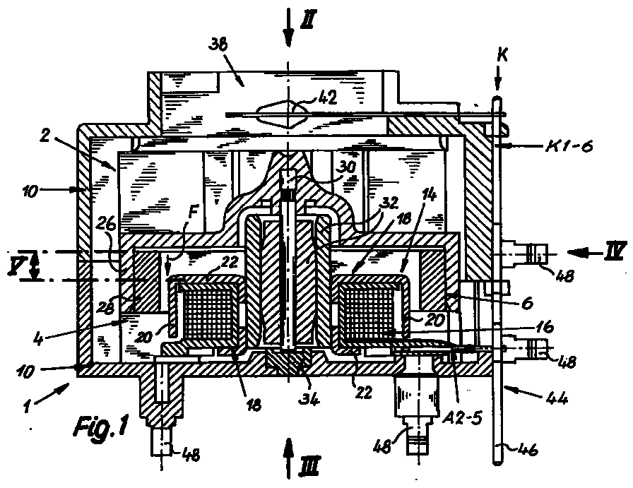
- FIGS. 1 and 11 points a small fan unit 1 according to the invention a fan wheel 2 and a collectorless DC motor driving this 4 on.
- This DC motor 4 is according to the invention as a single-phase, single-stranded claw-pole motor with one yoke-free permanent magnet rotor 6 is formed.
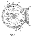
- 3 are preferably two diametrically opposite Positioning magnets 8 are provided which are at a standstill DC motor 4 act on the rotor 6 such that always a position ready to start (start position) of the Rotor 6 is effected.
- the small fan unit 1 has Housing 10 on.
- the positioning magnets 8 are in each case a pocket-like receptacle 12 of the housing 10 is arranged, so that they are radially outside of the rotor 6 approximately in the are axially covered by the rotor 16 area. Preferably each positioning magnet 8 sits quite exactly in the middle the axial length of the rotor 6. As a result, axial Vibrations and therefore annoying noises avoided.
- each claw pole plate 18 preferably has two diametrically opposed claw poles 20.
- Each claw pole extends from an annular disk-shaped, arranged on the respective end face of the ring coil 16 Sheet metal section 22 in the axial direction and has one in the circumferential direction circular arc-shaped contour, so that each claw pole 20 is located radially next to the ring coil 16 and covering almost the entire axial stator length.
- the two basically identical claw pole plates 18 lie on the axially opposite end faces the ring coil 16 and are in the circumferential direction offset from each other by 90 ° so that the claw poles 20 of the two claw pole plates 18 each in the circumferential direction alternate.
- the two basically identical claw pole plates 18 lie on the axially opposite end faces the ring coil 16 and are in the circumferential direction offset from each other by 90 ° so that the claw poles 20 of the two claw pole plates 18 each in the circumferential direction alternate.
- the ring coil 16 is preferably wound bifilar, whereby on the one hand a working winding and on the other hand a sensor winding (Speedometer winding) are formed.
- This can for motor control a very simple and extraordinary inexpensive control circuit can be used (not in shown), which are dependent on rotor position-dependent, induced signals from the sensor winding controls the work winding with one pulse (switches on and off).
- the claw poles 20 each by at least two, in particular as shown five, axially extending slots 24 interrupted. In other words, a number n ⁇ 2 slots is provided. This measure serves to reduce pole jerking and to avoid eddy current losses by the Pole surfaces are interrupted, in which otherwise eddy currents could be induced.
- the claw pole plates 18 from one to produce low-hysteresis material. This can be done with a soft magnetic nickel-iron alloy with 30 to 80% Nickel can be achieved. A material is particularly suitable which is known as "HYPERM 50". This material has particularly low hysteresis losses (Iron losses). The coercive field strength should be in Range from 4 to 10 A / m, but in particular approximately Do not exceed 8 A / m.
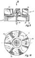
- the rotor 6 is principally an external rotor educated. It has an approximately hollow cylindrical one Receiving section 26 for an annular, permanent-magnetic Rotor magnet 28.
- This rotor magnet 28 can with Advantage from an originally strip-shaped, plastic deformable, especially plastic-bonded ferrite magnet be formed, with radial magnetization and number of poles 4.
- - cf. 9 and 10 in particular - is the rotor 6 or the receiving section 26 for the rotor magnet 28 in one piece with the Fan wheel 2 formed, and expediently as Molded part made of plastic.
- a shaft 30 becomes central molded. 1 and 11, this shaft 30 preferably runs in a double slide bearing 32, the free, End of the shaft 30 remote from the rotor 6 in a track bearing 34 axially supported. Otherwise, the shaft 30 runs without axial locking in the plain bearing 32.
- the bracket of the Rotor 6 against moving the shaft 30 out of the slide bearing 32 in the direction away from the thrust bearing 34 according to the invention exclusively by magnetic measures reached. For this purpose, is between the stator 14 and the rotor 6 an axial offset V (shown in FIGS.
- the axial offset V is in Dimensioned depending on the magnetic quantities in such a way that the rotor 6 is subjected to an axial acceleration a which is about four to seven times, in particular about five times the value of gravitational acceleration g corresponds. Hence a ⁇ 5 g.
- This measure will effectively prevents the basically unsecured Rotor 6 at high axial shock loads, such as those can often occur axially in motor vehicles storage is moved.
- according to the invention Measure even very small, insignificant Generated noises.
- Fan wheel 2 preferably as a radial impeller with essentially radially arranged blades 36 formed. These shovels 36 are in one piece on a flat bottom of the receiving section 26 integrally formed for the rotor magnet 28.
- the Housing 10 has according to FIGS. 1 and 2 or FIGS. 11 and 12 an axial air intake opening 38 and a radial exhaust opening 40 on.
- the outlet angle of the exhaust port 40 is very variable; he can look at almost the extend the entire circumference of the fan, as shown in FIG. 12 is indicated by thick dash lines.
- the suction opening 38 is an electric one Temperature sensor 42 arranged, in particular as an NTC sensor can be trained.
- the small fan unit 1 according to the invention forms the Temperature sensor 42 is part of a control circuit for an air conditioning system, in particular of a motor vehicle.
- the small fan unit 1 a special connection device 44 for electrical connection of the stator 14 or for the connection of its ring coil, i.e. the work winding and the sensor winding, and preferably for connecting the temperature sensor 42 on.
- the connection device 44 has on the one hand a contact set K with several, optionally usable or by possibly turning into a usage-specific one Contact position bringable contact elements K1 to K6 (Fig. 1 to 4) or K2 to K5 (Fig. 11 to 13). According to 4, the contact elements K1 to K6 run parallel to each other and to the rotor axis (shaft 30).
- the Contact elements K on the opposite of the suction opening 38 Flange-side pin ends 46 on the can be soldered directly into a circuit board.
- This Pin ends 46 can advantageously be in at least two different positions are bent, on the one hand in the illustrated, the flange side projecting axially parallel Arrangement or in a 90 ° (according to FIG. 1 after right) bent position.
- the invention Small fan unit optionally in at least two different arrangements directly on preferably be attached to a circuit board.
- additional brackets 48 are provided, which correspond to Openings e.g. a printed circuit board, in particular can be snapped into place.
- connection device 44 preferably has four pins A2 to A5, which are preferred in one formed as a plastic molded coil support 50 of the Ring coil 16 of the stator 14 are held. How in particular 7 shows are with the pins A2 up to A5 winding wire ends 52 of the two toroidal windings electrically connected, expediently by wrapping and soldering or welding. Furthermore are the connection pins A2 to A5, each with one of the contact elements K2 to K5 of the contact set K connected, in particular connected. Extend the pins A2 to A5 parallel to each other and perpendicular to the rotor axis and to the contact elements of the contact set K. The two outer contact elements K1 and K6 according to the embodiment 1 to 4 are used for the direct connection of connecting wires of the temperature sensor 42.
- the small fan unit 1 is suitable especially for use as a "circuit board fan", i.e. for direct arrangement on a circuit board and thus for Cooling of surrounding electrical or electronic Components.
- the small fan unit is an alternative or in addition 1 for use as a "sensor fan” in conjunction provided with air conditioning controls.
- the small fan unit 1 has the following dimensions, which however serve only as an example, whereby the invention is in no way restricted.
- Axial height about 18 to 25 mm
- Outer diameter about 30 mm
- Impeller diameter approx. 24 mm
- Axial length of the impeller approx. 6 mm
- Bucket incircle approx. 12
- Suction port diameter approx. 18 to 22 mm
- Rotor outer diameter approx. 23 to 25 mm
- Positioning magnet 5 x 3 x 1 mm
- Rotor magnet from a curved strip 60 5x4.5x1.8 mm
- Rotor shaft length 13 to 14 mm
- Coil carrier Inside ⁇ approx. 7 to 8 mm, Outside ⁇ approx. 15 mm, axial length approx. 5 to 6 mm, Ring coil: 2 windings each approx. 770 turns with approx. 140 to 150 ⁇ .
- the invention is not based on the illustrated and described Embodiments limited, but also includes all designs having the same effect in the sense of the invention. Furthermore, the invention is not yet based on the Claim 1 defined combination of features limited, but can also be by any other combination of certain characteristics of all of the individual characteristics disclosed be defined. This means that basically practically every single feature of claim 1 omitted or by at least one elsewhere in the registration disclosed individual feature can be replaced. To that extent is claim 1 only as a first attempt at formulation to understand for an invention.
Landscapes
- Engineering & Computer Science (AREA)
- Power Engineering (AREA)
- Mechanical Engineering (AREA)
- General Engineering & Computer Science (AREA)
- Connection Of Motors, Electrical Generators, Mechanical Devices, And The Like (AREA)
- Structures Of Non-Positive Displacement Pumps (AREA)
- Permanent Magnet Type Synchronous Machine (AREA)
- Cooling Or The Like Of Electrical Apparatus (AREA)
- Cookers (AREA)
- Brushless Motors (AREA)
- Dc Machiner (AREA)
- Motor Or Generator Cooling System (AREA)
Abstract
Vorgeschlagen wird, daß der Gleichstrommotor (4) als einphasiger, einsträngiger Klauenpolmotor mit einem rückschlußfreien Permanentmagnet-Rotor (6) ausgebildet ist, wobei mindestens ein eine Anlaufposition des Rotors (6) bewirkender Positioniermagnet (8) vorgesehen ist.
Description
- Fig. 1
- einen Axialschnitt durch eine erste Ausführungsform einer erfindungsgemäßen Kleinlüftereinheit,
- Fig. 2
- eine (etwas verkleinerte) Draufsicht auf die Seite einer Ansaugöffnung in Pfeilrichtung II gemäß Fig. 1,
- Fig. 3
- eine Ansicht auf die Flanschseite in Pfeilrichtung III genmäß Fig. 1,
- Fig. 4
- eine Seitenansicht in Pfeilrichtung IV gemäß Fig. 1,
- Fig. 5
- einen Axialschnitt durch die Stator-Ringspule,
- Fig. 6
- einen entsprechenden Schnitt durch ein Klauenpolblech in zur Montage lagerichtiger Zuordnung zur Stator-Ringspule gemäß Fig. 5,
- Fig. 7
- eine Ansicht der Ringspule in Pfeilrichtung VII gemäß Fig. 5,
- Fig. 8
- eine Ansicht des Klauenpolbleches in Pfeilrichtung VIII gemäß Fig. 6,
- Fig. 9
- einen Axialschnitt durch eine Rotor-Lüfterrad-Einheit,
- Fig. 10
- eine Draufsicht in Pfeilrichtung X gemäß Fig. 9,
- Fig. 11
- eine zweite Ausführungsform der erfindungsgemäßen Kleinlüftereinheit in einer Schnittdarstellung analog zu Fig. 1,
- Fig. 12
- eine verkleinerte Draufsicht in Pfeilrichtung XII gemäß Fig. 11 und
- Fig. 13
- eine entsprechend verkleinerte Seitenansicht in Pfeilrichtung XIII gemäß Fig. 12.
| Axiale Bauhöhe: | etwa 18 bis 25 mm |
| Außendurchmesser: | etwa 30 mm |
| Laufraddurchmesser: | ca. 24 mm |
| Axiale Länge des Laufrades: | ca. 6 mm |
| Schaufel-Inkreis: | ca. 12 mm |
| Durchmesser der Ansaugöffnung: | ca. 18 bis 22 mm |
| Rotor-Außendurchmesser: | ca. 23 bis 25 mm |
| Rotormagnet-Dicke (radial): | ca. 1,5 bis 2,0 mm |
| Rotormagnet-Länge (axial): | ca. 4 bis 5 mm |
| Positioniermagnet: | 5 x 3 x 1 mm |
| Rotormagnet aus einem gebogenen Streifen 60, | 5x4,5x1,8 mm |
| Rotorwellen-Länge: | 13 bis 14 mm |
| Spulenträger: | Innen-⊘ ca. 7 bis 8 mm, |
| Außen-⊘ ca. 15 mm, | |
| axiale Länge ca. 5 bis 6 mm, | |
| Ringspule: | 2 Wicklungen jeweils ca. 770 Windungen mit ca.140 bis 150 Ω. |
Claims (20)
- Kleinlüftereinheit (1) mit einem Lüfterrad (2) und einem dieses antreibenden, kollektorlosen Gleichstrommotor (4), insbesondere zur direkten Anordnung auf einer Leiterplatte,
dadurch gekennzeichnet, daß der Gleichstrommotor (4) als einphasiger, einsträngiger Klauenpolmotor mit einem rückschlußfreien Permanentmagnet-Rotor (6) ausgebildet ist, wobei mindestens ein eine Anlaufposition des Rotors (6) bewirkender Positioniermagnet (8) vorgesehen ist. - Kleinlüftereinheit nach Anspruch 1,
dadurch gekennzeichnet, daß der Gleichstrommotor (4) einen Stator (14) mit einer koaxialen Ringspule (16) und zwei axial gegenüberliegenden Klauenpolblechen (18) mit jeweils insbesondere zwei Klauenpolen (20) aufweist. - Kleinlüftereinheit nach Anspruch 2,
dadurch gekennzeichnet, daß die Ringspule (16) bifilar gewickelt ist und eine Arbeitswicklung und eine Sensorwicklung aufweist, wobei eine Steuerschaltung vorgesehen ist, die in Abhängigkeit von rotorstellungsabhängigen, induzierten Signalen der Sensorwicklung die Arbeitswicklung einpulsig ansteuert. - Kleinlüftereinheit nach Anspruch 2 oder 3,
dadurch gekennzeichnet, daß die Klauenpole (20) durch mindestens zwei - vorzugsweise jeweils vier bis sechs, insbesondere fünf - Schlitze (24) unterbrochen sind. - Kleinlüftereinheit nach einem der Ansprüche 2 bis 4,
dadurch gekennzeichnet, daß die Klauenpolbleche (18) aus einem hysteresearmen Material, insbesondere einer weichmagnetischen Nickel-Eisen-Legierung mit 30 bis 80% Nickel, bestehen. - Kleinlüftereinheit nach einem der Ansprüche 2 bis 5,
dadurch gekennzeichnet, daß die Klauenpolbleche (18) aus einem Material mit einer Koerzitivfeldstärke im Bereich von 4 bis 10 A/m, insbesondere maximal etwa 8 A/m, bestehen. - Kleinlüftereinheit nach einem der Ansprüche 1 bis 6,
dadurch gekennzeichnet, daß der Rotor (6) als Außenläufer ausgebildet ist und einen etwa hohlzylindrischen Aufnahmeabschnitt (26) für einen ringförmigen, permanentmagnetischen Rotormagnet (28) aufweist. - Kleinlüftereinheit nach Anspruch 7,
dadurch gekennzeichnet, daß der Rotormagnet (28) aus einem plastisch verformbaren und/oder kunststoffgebundenen Ferritmagnet gebildet ist. - Kleinlüftereinheit nach einem der Ansprüche 1 bis 8,
dadurch gekennzeichnet, daß der Rotor (6) einstückig mit dem Lüfterrad (2) ausgebildet ist. - Kleinlüftereinheit nach einem der Ansprüche 1 bis 9,
dadurch gekennzeichnet, daß das Lüfterrad (2) als Radiallaufrad mit im wesentlichen radial angeordneten Schaufeln (36) ausgebildet ist. - Kleinlüftereinheit nach einem der Ansprüche 1 bis 10,
gekennzeichnet, durch ein Gehäuse (10) mit einer - insbesondere axialen - Luft-Ansaugöffnung (38) und einer - insbesondere radialen - Ausblasöffnung (40). - Kleinlüftereinheit nach einem der Ansprüche 1 bis 11,
dadurch gekennzeichnet, daß der Positioniermagnet (8) - bzw. jeder von vorzugsweise zwei diametral gegenüberliegend angeordneten Positioniermagneten (8) - in einer taschenartigen Aufnahme (12) des Gehäuses (10) sitzt. - Kleinlüftereinheit nach Anspruch 12,
dadurch gekennzeichnet, daß der bzw. jeder Positioniermagnet (8) in der Mitte der axialen Länge des Rotormagneten (28) sitzt. - Kleinlüftereinheit nach einem der Ansprüche 1 bis 13,
dadurch gekennzeichnet, daß zwischen dem Stator (14) und dem Rotor (6) ein axialer Versatz (V) zur Erzeugung einer axialen Rotor-Haltekraft (F) gebildet ist. - Kleinlüftereinheit nach Anspruch 14,
dadurch gekennzeichnet, daß der axiale Versatz (V) zwischen Stator (14) und Rotor (6) in Abhängigkeit von den magnetischen Eigenschaften derart bemessen ist, daß der Rotor (6) mit einer axialen Beschleunigung (a) beaufschlagt wird, die etwa dem vier- bis siebenfachen, inbesondere etwa dem fünffachen, Wert der Erdbeschleunigung (g) entspricht. - Kleinlüftereinheit nach Anspruch 14 oder 15,
dadurch gekennzeichnet, daß der axiale Versatz (V) zwischen Stator (14) und Rotor (6) in der Größenordnung von etwa 40 bis 60%, insbesondere etwa 50%, der axialen Länge des Stators (14) liegt. - Kleinlüftereinheit nach einem der Ansprüche 11 bis 16,
dadurch gekennzeichnet, daß im Luftströmungsbereich der Ansaugöffnung (38) und/oder der Ausblasöffnung (40) ein elektrischer Temperatursensor (42), insbesondere ein NTC-Fühler, angeordnet ist. - Kleinlüftereinheit nach einem der Ansprüche 1 bis 17,
gekennzeichnet durch eine Anschlußeinrichtung (44) zum elektrischen Anschluß des Stators. - Kleinlüftereinheit nach Anspruch 18,
dadurch gekennzeichnet, daß die Anschlußeinrichtung (44) einen Kontaktsatz (K) mit mehreren, wahlweise benutzbaren bzw. durch eventuelles Umbiegen in eine verwendungsspezifische Anschlußposition bringbaren Kontaktelementen (K1 bis K6/K2 bis K5) aufweist. - Kleinlüftereinheit nach Anspruch 18 oder 19,
dadurch gekennzeichnet, daß die Ringspule (16) des Stators (14) einen Spulenträger (50) aufweist, in dem Anschlußstifte (A2 bis A5) gehaltert sind, wobei mit den Anschlußstiften (A2 bis A5) Wicklungsdrahtenden (52) der Ringspulen-Wicklungen elektrisch verbunden sind, und wobei die Anschlußstifte (A2 bis A5) mit jeweils einem der Kontaktelemente (K2 bis K5) des Kontaktsatzes (K) verbunden sind.
Applications Claiming Priority (2)
| Application Number | Priority Date | Filing Date | Title |
|---|---|---|---|
| DE29718082U DE29718082U1 (de) | 1997-10-11 | 1997-10-11 | Kleinlüftereinheit, insbesondere zur Verwendung als Leiterplattenlüfter |
| DE29718082U | 1997-10-11 |
Publications (2)
| Publication Number | Publication Date |
|---|---|
| EP0908630A1 true EP0908630A1 (de) | 1999-04-14 |
| EP0908630B1 EP0908630B1 (de) | 2003-04-23 |
Family
ID=8047117
Family Applications (1)
| Application Number | Title | Priority Date | Filing Date |
|---|---|---|---|
| EP98114778A Expired - Lifetime EP0908630B1 (de) | 1997-10-11 | 1998-08-06 | Kleinlüftereinheit, insbesondere zur Verwendung als Leiterplattenlüfter |
Country Status (5)
| Country | Link |
|---|---|
| US (1) | US6013966A (de) |
| EP (1) | EP0908630B1 (de) |
| JP (1) | JP4104747B2 (de) |
| AT (1) | ATE238496T1 (de) |
| DE (2) | DE29718082U1 (de) |
Cited By (5)
| Publication number | Priority date | Publication date | Assignee | Title |
|---|---|---|---|---|
| EP1107441A2 (de) | 1999-12-01 | 2001-06-13 | Papst-Motoren GmbH & Co. KG | Elektronisch kommunierter Gleichstrommotor |
| US6429615B2 (en) | 1999-12-08 | 2002-08-06 | Papst Motoren Gmbh & Co. Kg | Electronically commutated DC motor |
| US6995534B2 (en) | 2001-08-10 | 2006-02-07 | Ebm-Papst St. Georgen Gmbh & Co. Kg | Method of controlling the commutation in an electronically commutated motor, and an electronically commutated motor for carrying out said method |
| US7841541B2 (en) | 2003-11-12 | 2010-11-30 | Ebm-Papst St. Georgen Gmbh & Co. Kg | Fan having a sensor |
| BE1030312B1 (de) * | 2022-02-23 | 2023-10-02 | Miele & Cie | Strömungsmaschine |
Families Citing this family (37)
| Publication number | Priority date | Publication date | Assignee | Title |
|---|---|---|---|---|
| ES2238302T3 (es) * | 1999-07-17 | 2005-09-01 | EBM-PAPST ST. GEORGEN GMBH & CO. KG | Motor electrico pequeño con cojinete axial. |
| JP2002186212A (ja) * | 2000-12-11 | 2002-06-28 | Tamagawa Seiki Co Ltd | プリント基板を有するステータ構造 |
| US6864616B2 (en) * | 2001-10-09 | 2005-03-08 | General Electric Company | Method and apparatus for forming an electric motor having stacked laminations |
| EP1464106A1 (de) * | 2002-01-11 | 2004-10-06 | ebm-papst St. Georgen GmbH & Co. KG | KLEIN- ODER KLEINSTLüFTER |
| TW534241U (en) * | 2002-07-10 | 2003-05-21 | Sunonwealth Electr Mach Ind Co | Dustproof bearing structure |
| TW566837U (en) * | 2003-04-23 | 2003-12-11 | Delta Electronics Inc | Fan motor structure |
| TWI222263B (en) * | 2003-08-15 | 2004-10-11 | Delta Electronics Inc | Non-bearing motor |
| KR100774793B1 (ko) | 2003-09-10 | 2007-11-07 | 세이코 엡슨 가부시키가이샤 | 팬 유닛과, 열교환 시스템 |
| JP4507553B2 (ja) | 2003-10-23 | 2010-07-21 | パナソニック株式会社 | クロスフローファン及びクロスフローファンの製造方法 |
| US8801375B2 (en) * | 2004-03-30 | 2014-08-12 | EBM-Pabst St. Georgen GmbH & Co. KG | Fan arrangement |
| TWI247472B (en) * | 2004-08-27 | 2006-01-11 | Delta Electronics Inc | Stator structure |
| TWI249898B (en) * | 2004-08-27 | 2006-02-21 | Delta Electronics Inc | Brushless DC motor and driver used therein |
| US7390172B2 (en) * | 2004-10-19 | 2008-06-24 | Ebm-Papst St. Georgen Gmbh & Co. Kg | Assembly used for cooling a circuit board or similar |
| US7282823B2 (en) * | 2004-10-29 | 2007-10-16 | Emerson Electric Co. | Self-cooling electric machine |
| DE202005003413U1 (de) * | 2005-02-24 | 2006-07-13 | Ebm-Papst St. Georgen Gmbh & Co. Kg | Minilüfter |
| US20070134109A1 (en) * | 2005-02-24 | 2007-06-14 | Rodica Peia | Mini-fan |
| DE602005008554D1 (de) * | 2005-04-07 | 2008-09-11 | Harman Becker Automotive Sys | Ventilateur |
| CA2612932C (en) * | 2005-07-26 | 2014-01-21 | Ebm-Papst St. Georgen Gmbh & Co. Kg | Absolute encoder and method for generating an absolute value for an angle of rotation |
| KR100887535B1 (ko) * | 2007-04-10 | 2009-03-09 | 주식회사 아모텍 | 어스피레이션 모터용 스테이터, 이를 이용한 어스피레이션모터 및 인카 센서 |
| EP2158403B1 (de) * | 2007-06-28 | 2010-11-17 | Ebm-Papst St. Georgen GmbH & CO. KG | Lüfter mit einer leiterplatte |
| US20090028476A1 (en) * | 2007-07-24 | 2009-01-29 | Chi Ai | Anti-leakage device in a fan for an oily bearing |
| WO2009089857A1 (de) * | 2008-01-18 | 2009-07-23 | Ebm-Papst St. Georgen Gmbh & Co Kg | Lüfter mit einem sensor |
| TW201020400A (en) * | 2008-11-27 | 2010-06-01 | Compal Electronics Inc | Fan module for electronic device |
| JP5249860B2 (ja) * | 2009-06-03 | 2013-07-31 | 建準電機工業股▲分▼有限公司 | 放熱ファン |
| US8277203B2 (en) * | 2009-07-02 | 2012-10-02 | Sunonwealth Electric Machine Industry Co., Ltd. | DC fan of inner rotor type |
| US8556601B2 (en) * | 2009-12-16 | 2013-10-15 | Pc-Fan Technology Inc. | Heat-dissipating fan assembly |
| USD703301S1 (en) | 2011-08-08 | 2014-04-22 | Ebm-Papst St. Georgen Gmbh & Co. Kg | Axial fan |
| DE102011087117B4 (de) * | 2011-11-25 | 2023-07-20 | Hilti Aktiengesellschaft | Elektrischer Antrieb für eine Handwerkzeugmaschine |
| JP5659208B2 (ja) * | 2012-10-22 | 2015-01-28 | シナノケンシ株式会社 | 送風機 |
| KR20140079651A (ko) * | 2012-12-18 | 2014-06-27 | 삼성전기주식회사 | 회전축 지지모듈 및 이를 포함하는 외전형 팬 모터 |
| TWI530620B (zh) | 2013-09-02 | 2016-04-21 | Sunonwealth Electr Mach Ind Co | Chassis and fan with temperature sensing element |
| US10651709B2 (en) * | 2017-05-09 | 2020-05-12 | Gentherm Incorporated | Fan arbor grounding |
| RU2703992C1 (ru) * | 2019-03-13 | 2019-10-23 | Дмитрий Валерьевич Быков | Электрическая машина (варианты) |
| DE102019114068B4 (de) * | 2019-05-27 | 2022-06-09 | Ebm-Papst St. Georgen Gmbh & Co. Kg | Ventilatorbaugruppe mit variabel einstellbarem Steckverbinderabgang |
| US11519415B2 (en) | 2020-04-02 | 2022-12-06 | Hanon Systems EFP Canada Ltd. | Automotive accessory having an electromagnet pulley assist mechanism equipped with circumferentially spaced teeth nested with a conductive body |
| CN111564951B (zh) * | 2020-05-28 | 2022-01-07 | 歌尔股份有限公司 | 直线电机 |
| JP2022111518A (ja) * | 2021-01-20 | 2022-08-01 | 日本電産株式会社 | ステータ、およびモータ |
Citations (7)
| Publication number | Priority date | Publication date | Assignee | Title |
|---|---|---|---|---|
| FR2533085A1 (fr) * | 1982-09-10 | 1984-03-16 | Rotron Inc | Moteur a courant continu sans balai, notamment pour ventilateur |
| EP0299512A2 (de) * | 1987-07-16 | 1989-01-18 | Minebea Co. Ltd. | Bürstenloser Gleichstrommotor |
| DE3821557C1 (en) * | 1988-06-25 | 1989-10-12 | Robert Bosch Gmbh, 7000 Stuttgart, De | Electronically commutated miniature DC motor |
| DE9100952U1 (de) * | 1990-01-27 | 1991-05-29 | Papst-Motoren GmbH & Co KG, 7742 St Georgen | Elektromotor zum Betrieb in einem resonanzfähigen Gerät |
| DE29501695U1 (de) * | 1994-02-05 | 1995-06-08 | Papst-Motoren GmbH & Co KG, 78112 St Georgen | Lüfter mit einem Lüfterrad |
| JPH08214524A (ja) * | 1995-01-31 | 1996-08-20 | Nippon Densan Corp | ブラシレスモータ及びそのドライブ方式 |
| US5591017A (en) * | 1994-10-03 | 1997-01-07 | Ametek, Inc. | Motorized impeller assembly |
Family Cites Families (10)
| Publication number | Priority date | Publication date | Assignee | Title |
|---|---|---|---|---|
| US3840761A (en) * | 1972-05-25 | 1974-10-08 | Papst Motoren Kg | Axial air gap,collector-less d-c motor |
| US4169990A (en) * | 1974-06-24 | 1979-10-02 | General Electric Company | Electronically commutated motor |
| US4779165A (en) * | 1981-09-07 | 1988-10-18 | Papst-Motoren Gmbh & Co. Kg | Disk storage drive |
| CH654455A5 (de) * | 1980-05-10 | 1986-02-14 | Papst Motoren Gmbh & Co Kg | Buerstenlose gleichstrommotoranordnung, insbesondere fuer magnetplattenantriebe. |
| US4682065A (en) * | 1985-11-13 | 1987-07-21 | Nidec-Torin Corporation | Molded plastic motor housing with integral stator mounting and shaft journalling projection |
| GB8802601D0 (en) * | 1988-02-05 | 1988-03-02 | Johnson Electric Ind Mfg | Brushless d c electric motor |
| DE9012087U1 (de) * | 1990-08-22 | 1992-01-02 | Papst Licensing GmbH & Co. KG, 78549 Spaichingen | Flachbauendes Kleingebläse |
| JPH0548557U (ja) * | 1991-11-21 | 1993-06-25 | マブチモーター株式会社 | 小型モータ |
| TW263629B (de) * | 1992-05-27 | 1995-11-21 | Nihon Densan Kk | |
| US5782652A (en) * | 1996-05-23 | 1998-07-21 | The Whitaker Corporation | Electrical connector assembly for a magnet wire |
-
1997
- 1997-10-11 DE DE29718082U patent/DE29718082U1/de not_active Expired - Lifetime
-
1998
- 1998-08-06 DE DE59808030T patent/DE59808030D1/de not_active Expired - Lifetime
- 1998-08-06 EP EP98114778A patent/EP0908630B1/de not_active Expired - Lifetime
- 1998-08-06 AT AT98114778T patent/ATE238496T1/de not_active IP Right Cessation
- 1998-10-09 US US09/169,672 patent/US6013966A/en not_active Expired - Lifetime
- 1998-10-12 JP JP28928598A patent/JP4104747B2/ja not_active Expired - Fee Related
Patent Citations (7)
| Publication number | Priority date | Publication date | Assignee | Title |
|---|---|---|---|---|
| FR2533085A1 (fr) * | 1982-09-10 | 1984-03-16 | Rotron Inc | Moteur a courant continu sans balai, notamment pour ventilateur |
| EP0299512A2 (de) * | 1987-07-16 | 1989-01-18 | Minebea Co. Ltd. | Bürstenloser Gleichstrommotor |
| DE3821557C1 (en) * | 1988-06-25 | 1989-10-12 | Robert Bosch Gmbh, 7000 Stuttgart, De | Electronically commutated miniature DC motor |
| DE9100952U1 (de) * | 1990-01-27 | 1991-05-29 | Papst-Motoren GmbH & Co KG, 7742 St Georgen | Elektromotor zum Betrieb in einem resonanzfähigen Gerät |
| DE29501695U1 (de) * | 1994-02-05 | 1995-06-08 | Papst-Motoren GmbH & Co KG, 78112 St Georgen | Lüfter mit einem Lüfterrad |
| US5591017A (en) * | 1994-10-03 | 1997-01-07 | Ametek, Inc. | Motorized impeller assembly |
| JPH08214524A (ja) * | 1995-01-31 | 1996-08-20 | Nippon Densan Corp | ブラシレスモータ及びそのドライブ方式 |
Non-Patent Citations (1)
| Title |
|---|
| PATENT ABSTRACTS OF JAPAN vol. 096, no. 012 26 December 1996 (1996-12-26) * |
Cited By (6)
| Publication number | Priority date | Publication date | Assignee | Title |
|---|---|---|---|---|
| EP1107441A2 (de) | 1999-12-01 | 2001-06-13 | Papst-Motoren GmbH & Co. KG | Elektronisch kommunierter Gleichstrommotor |
| US6396226B2 (en) | 1999-12-01 | 2002-05-28 | Papst Motoren Gmbh & Co. Kg | Electronically commutated DC motor |
| US6429615B2 (en) | 1999-12-08 | 2002-08-06 | Papst Motoren Gmbh & Co. Kg | Electronically commutated DC motor |
| US6995534B2 (en) | 2001-08-10 | 2006-02-07 | Ebm-Papst St. Georgen Gmbh & Co. Kg | Method of controlling the commutation in an electronically commutated motor, and an electronically commutated motor for carrying out said method |
| US7841541B2 (en) | 2003-11-12 | 2010-11-30 | Ebm-Papst St. Georgen Gmbh & Co. Kg | Fan having a sensor |
| BE1030312B1 (de) * | 2022-02-23 | 2023-10-02 | Miele & Cie | Strömungsmaschine |
Also Published As
| Publication number | Publication date |
|---|---|
| DE59808030D1 (de) | 2003-05-28 |
| JPH11218092A (ja) | 1999-08-10 |
| EP0908630B1 (de) | 2003-04-23 |
| JP4104747B2 (ja) | 2008-06-18 |
| US6013966A (en) | 2000-01-11 |
| ATE238496T1 (de) | 2003-05-15 |
| DE29718082U1 (de) | 1999-02-11 |
Similar Documents
| Publication | Publication Date | Title |
|---|---|---|
| EP0908630B1 (de) | Kleinlüftereinheit, insbesondere zur Verwendung als Leiterplattenlüfter | |
| EP0691727B1 (de) | Mittels Permanentmagneten erregbarer elektrischer Motor, insbesondere Innenläufer- oder Aussenläufermotor | |
| DE69620284T2 (de) | Elektrische Rotationsmaschine | |
| DE69501066T3 (de) | Synchronmotor mit im Rotor eingebetteten Permanentmagneten | |
| DE102019107398A1 (de) | Axialflussrotor und elektrische axialflussmaschine | |
| DE102019214623B4 (de) | Synchronmaschine, elektrische Antriebseinrichtung umfassend eine Synchronmaschine, sowie Ansteuerverfahren für eine Synchronmaschine | |
| DE102020113905A1 (de) | Axial-Fluss-Maschine | |
| WO2000011776A1 (de) | Elektrische maschine mit einem um einen stator rotierenden rotor | |
| DE102004017507A1 (de) | Rotoranordnung für eine elektrische Maschine | |
| DE102008019734A1 (de) | Elektrische Maschine und Rotor für dieselbe | |
| EP0246410A2 (de) | Induktionsmotor | |
| DE10141870B4 (de) | Hybriderregter Läufer für eine Elektromaschine | |
| DE102008044276A1 (de) | Hybriderregte elektrische Maschine mit polumschaltbarem Rotor | |
| DE60109110T2 (de) | Läufer eines Drehfeld- Wechselstromgenerators | |
| DE3844074C2 (de) | ||
| DE8702271U1 (de) | Kollektorloser Gleichstrommotor mit permanentmagnetischem Rotor | |
| WO2011151138A2 (de) | Elektrische maschine mit reduzierter geräuschentwicklung | |
| DE102014011585A1 (de) | Elektrische Maschine | |
| DE3804549C2 (de) | Kleingebläse mit einem Ventilatorlaufrad | |
| WO2010088997A1 (de) | Gleichstrommotor | |
| DE102008041605A1 (de) | Hybriderregte elektrische Maschine | |
| DE3915356A1 (de) | Elektromotor in resonanzfaehigem geraet | |
| WO2002041471A1 (de) | Rotor für eine elektrische maschine | |
| DE3821557C1 (en) | Electronically commutated miniature DC motor | |
| DE102014115931A1 (de) | Türantrieb |
Legal Events
| Date | Code | Title | Description |
|---|---|---|---|
| PUAI | Public reference made under article 153(3) epc to a published international application that has entered the european phase |
Free format text: ORIGINAL CODE: 0009012 |
|
| AK | Designated contracting states |
Kind code of ref document: A1 Designated state(s): AT BE CH DE DK ES FI FR GB IE IT LI LU NL PT SE |
|
| AX | Request for extension of the european patent |
Free format text: AL;LT;LV;MK;RO;SI |
|
| 17P | Request for examination filed |
Effective date: 19990430 |
|
| AKX | Designation fees paid |
Free format text: AT BE CH DE DK ES FI FR GB IE IT LI LU NL PT SE |
|
| 17Q | First examination report despatched |
Effective date: 20020710 |
|
| GRAH | Despatch of communication of intention to grant a patent |
Free format text: ORIGINAL CODE: EPIDOS IGRA |
|
| RIN1 | Information on inventor provided before grant (corrected) |
Inventor name: SCHMIDER, FRITZ Inventor name: MOINI, MOJTABA, DIPL.-ING. Inventor name: FEHRENBACHER, WOLFGANG |
|
| GRAH | Despatch of communication of intention to grant a patent |
Free format text: ORIGINAL CODE: EPIDOS IGRA |
|
| GRAA | (expected) grant |
Free format text: ORIGINAL CODE: 0009210 |
|
| AK | Designated contracting states |
Designated state(s): AT BE CH DE DK ES FI FR GB IE IT LI LU NL PT SE |
|
| PG25 | Lapsed in a contracting state [announced via postgrant information from national office to epo] |
Ref country code: NL Free format text: LAPSE BECAUSE OF FAILURE TO SUBMIT A TRANSLATION OF THE DESCRIPTION OR TO PAY THE FEE WITHIN THE PRESCRIBED TIME-LIMIT Effective date: 20030423 Ref country code: IE Free format text: LAPSE BECAUSE OF NON-PAYMENT OF DUE FEES Effective date: 20030423 Ref country code: FI Free format text: LAPSE BECAUSE OF FAILURE TO SUBMIT A TRANSLATION OF THE DESCRIPTION OR TO PAY THE FEE WITHIN THE PRESCRIBED TIME-LIMIT Effective date: 20030423 |
|
| REG | Reference to a national code |
Ref country code: GB Ref legal event code: FG4D Free format text: NOT ENGLISH |
|
| REG | Reference to a national code |
Ref country code: CH Ref legal event code: EP |
|
| REF | Corresponds to: |
Ref document number: 59808030 Country of ref document: DE Date of ref document: 20030528 Kind code of ref document: P |
|
| REG | Reference to a national code |
Ref country code: IE Ref legal event code: FG4D Free format text: GERMAN |
|
| GBT | Gb: translation of ep patent filed (gb section 77(6)(a)/1977) | ||
| PG25 | Lapsed in a contracting state [announced via postgrant information from national office to epo] |
Ref country code: PT Free format text: LAPSE BECAUSE OF FAILURE TO SUBMIT A TRANSLATION OF THE DESCRIPTION OR TO PAY THE FEE WITHIN THE PRESCRIBED TIME-LIMIT Effective date: 20030723 Ref country code: DK Free format text: LAPSE BECAUSE OF FAILURE TO SUBMIT A TRANSLATION OF THE DESCRIPTION OR TO PAY THE FEE WITHIN THE PRESCRIBED TIME-LIMIT Effective date: 20030723 |
|
| REG | Reference to a national code |
Ref country code: SE Ref legal event code: TRGR |
|
| PG25 | Lapsed in a contracting state [announced via postgrant information from national office to epo] |
Ref country code: LU Free format text: LAPSE BECAUSE OF NON-PAYMENT OF DUE FEES Effective date: 20030806 Ref country code: AT Free format text: LAPSE BECAUSE OF NON-PAYMENT OF DUE FEES Effective date: 20030806 |
|
| PG25 | Lapsed in a contracting state [announced via postgrant information from national office to epo] |
Ref country code: LI Free format text: LAPSE BECAUSE OF NON-PAYMENT OF DUE FEES Effective date: 20030831 Ref country code: CH Free format text: LAPSE BECAUSE OF NON-PAYMENT OF DUE FEES Effective date: 20030831 Ref country code: BE Free format text: LAPSE BECAUSE OF NON-PAYMENT OF DUE FEES Effective date: 20030831 |
|
| NLV1 | Nl: lapsed or annulled due to failure to fulfill the requirements of art. 29p and 29m of the patents act | ||
| PG25 | Lapsed in a contracting state [announced via postgrant information from national office to epo] |
Ref country code: ES Free format text: LAPSE BECAUSE OF FAILURE TO SUBMIT A TRANSLATION OF THE DESCRIPTION OR TO PAY THE FEE WITHIN THE PRESCRIBED TIME-LIMIT Effective date: 20031030 |
|
| REG | Reference to a national code |
Ref country code: IE Ref legal event code: FD4D Ref document number: 0908630E Country of ref document: IE |
|
| ET | Fr: translation filed | ||
| PLBE | No opposition filed within time limit |
Free format text: ORIGINAL CODE: 0009261 |
|
| STAA | Information on the status of an ep patent application or granted ep patent |
Free format text: STATUS: NO OPPOSITION FILED WITHIN TIME LIMIT |
|
| BERE | Be: lapsed |
Owner name: *PAPST-MOTOREN G.M.B.H. & CO. K.G. Effective date: 20030831 |
|
| 26N | No opposition filed |
Effective date: 20040126 |
|
| REG | Reference to a national code |
Ref country code: CH Ref legal event code: PL |
|
| REG | Reference to a national code |
Ref country code: FR Ref legal event code: PLFP Year of fee payment: 19 |
|
| REG | Reference to a national code |
Ref country code: FR Ref legal event code: PLFP Year of fee payment: 20 |
|
| PGFP | Annual fee paid to national office [announced via postgrant information from national office to epo] |
Ref country code: FR Payment date: 20170623 Year of fee payment: 20 |
|
| PGFP | Annual fee paid to national office [announced via postgrant information from national office to epo] |
Ref country code: IT Payment date: 20170531 Year of fee payment: 20 |
|
| PGFP | Annual fee paid to national office [announced via postgrant information from national office to epo] |
Ref country code: DE Payment date: 20170801 Year of fee payment: 20 Ref country code: GB Payment date: 20170929 Year of fee payment: 20 |
|
| PGFP | Annual fee paid to national office [announced via postgrant information from national office to epo] |
Ref country code: SE Payment date: 20170814 Year of fee payment: 20 |
|
| REG | Reference to a national code |
Ref country code: DE Ref legal event code: R071 Ref document number: 59808030 Country of ref document: DE |
|
| REG | Reference to a national code |
Ref country code: GB Ref legal event code: PE20 Expiry date: 20180805 |
|
| REG | Reference to a national code |
Ref country code: SE Ref legal event code: EUG |
|
| PG25 | Lapsed in a contracting state [announced via postgrant information from national office to epo] |
Ref country code: GB Free format text: LAPSE BECAUSE OF EXPIRATION OF PROTECTION Effective date: 20180805 |