EP1106963B1 - Abstandsmessgerät und Verfahren zur Regelung der Photodetektoreinheit - Google Patents
Abstandsmessgerät und Verfahren zur Regelung der Photodetektoreinheit Download PDFInfo
- Publication number
- EP1106963B1 EP1106963B1 EP00310876.8A EP00310876A EP1106963B1 EP 1106963 B1 EP1106963 B1 EP 1106963B1 EP 00310876 A EP00310876 A EP 00310876A EP 1106963 B1 EP1106963 B1 EP 1106963B1
- Authority
- EP
- European Patent Office
- Prior art keywords
- light
- photodetection
- emitting element
- adjustment
- distance measuring
- Prior art date
- Legal status (The legal status is an assumption and is not a legal conclusion. Google has not performed a legal analysis and makes no representation as to the accuracy of the status listed.)
- Expired - Lifetime
Links
Images


Classifications
-
- G—PHYSICS
- G01—MEASURING; TESTING
- G01S—RADIO DIRECTION-FINDING; RADIO NAVIGATION; DETERMINING DISTANCE OR VELOCITY BY USE OF RADIO WAVES; LOCATING OR PRESENCE-DETECTING BY USE OF THE REFLECTION OR RERADIATION OF RADIO WAVES; ANALOGOUS ARRANGEMENTS USING OTHER WAVES
- G01S17/00—Systems using the reflection or reradiation of electromagnetic waves other than radio waves, e.g. lidar systems
- G01S17/02—Systems using the reflection of electromagnetic waves other than radio waves
- G01S17/06—Systems determining position data of a target
- G01S17/08—Systems determining position data of a target for measuring distance only
-
- G—PHYSICS
- G01—MEASURING; TESTING
- G01C—MEASURING DISTANCES, LEVELS OR BEARINGS; SURVEYING; NAVIGATION; GYROSCOPIC INSTRUMENTS; PHOTOGRAMMETRY OR VIDEOGRAMMETRY
- G01C3/00—Measuring distances in line of sight; Optical rangefinders
- G01C3/02—Details
- G01C3/06—Use of electric means to obtain final indication
- G01C3/08—Use of electric radiation detectors
-
- G—PHYSICS
- G01—MEASURING; TESTING
- G01S—RADIO DIRECTION-FINDING; RADIO NAVIGATION; DETERMINING DISTANCE OR VELOCITY BY USE OF RADIO WAVES; LOCATING OR PRESENCE-DETECTING BY USE OF THE REFLECTION OR RERADIATION OF RADIO WAVES; ANALOGOUS ARRANGEMENTS USING OTHER WAVES
- G01S7/00—Details of systems according to groups G01S13/00, G01S15/00, G01S17/00
- G01S7/48—Details of systems according to groups G01S13/00, G01S15/00, G01S17/00 of systems according to group G01S17/00
- G01S7/491—Details of non-pulse systems
- G01S7/4911—Transmitters
-
- G—PHYSICS
- G01—MEASURING; TESTING
- G01S—RADIO DIRECTION-FINDING; RADIO NAVIGATION; DETERMINING DISTANCE OR VELOCITY BY USE OF RADIO WAVES; LOCATING OR PRESENCE-DETECTING BY USE OF THE REFLECTION OR RERADIATION OF RADIO WAVES; ANALOGOUS ARRANGEMENTS USING OTHER WAVES
- G01S7/00—Details of systems according to groups G01S13/00, G01S15/00, G01S17/00
- G01S7/48—Details of systems according to groups G01S13/00, G01S15/00, G01S17/00 of systems according to group G01S17/00
- G01S7/491—Details of non-pulse systems
- G01S7/4912—Receivers
- G01S7/4913—Circuits for detection, sampling, integration or read-out
-
- G—PHYSICS
- G01—MEASURING; TESTING
- G01S—RADIO DIRECTION-FINDING; RADIO NAVIGATION; DETERMINING DISTANCE OR VELOCITY BY USE OF RADIO WAVES; LOCATING OR PRESENCE-DETECTING BY USE OF THE REFLECTION OR RERADIATION OF RADIO WAVES; ANALOGOUS ARRANGEMENTS USING OTHER WAVES
- G01S7/00—Details of systems according to groups G01S13/00, G01S15/00, G01S17/00
- G01S7/48—Details of systems according to groups G01S13/00, G01S15/00, G01S17/00 of systems according to group G01S17/00
- G01S7/491—Details of non-pulse systems
- G01S7/4912—Receivers
- G01S7/4918—Controlling received signal intensity, gain or exposure of sensor
Definitions
- the present invention relates to a distance measuring device, in which sensitivity of a photodetection unit of a distance measuring device is easily adjustable, and the invention also relates to a method for adjusting the photodetection unit of the distance measuring device.
- a modulated measuring light beam is used, and a distance is determined from a phase difference of the reflected light beam.
- Fig. 4 is a drawing to explain a basic type of a distance measuring unit 1 of a distance measuring device
- Fig. 5 is a block diagram to explain the control unit 13 of the distance measuring device.
- a distance measuring light beam 4 When a distance measuring light beam 4 is emitted from a light emitting element 3 which is modulated and driven by an oscillator 2, the distance measuring light 4 is turned to a parallel beam by an objective lens 5 and this beam is projected to a reflection prism 6, which is an object to be measured.
- the distance measuring light 4 reflected by the reflection prism 6 enters the objective lens 5 again and is received by a photodetection element 7.
- a part of the distance measuring light beam emitted from the light emitting element 3 is reflected by a reflection mirror 9 and it is received by the photodetection element 7 as an internal reference light beam 12.
- the distance is calculated from the phase difference by a distance measuring circuit 8.
- the distance to the object to be measured (the reflection prism 6) as obtained by the distance measuring circuit 8 is displayed on a display unit 15 as a numerical value indicating the distance based on the control by a CPU 14.
- Distance measuring instruction, data, etc. are inputted from a keyboard unit 16.
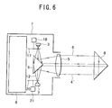
- Fig. 6 is a drawing to explain the distance measuring unit 1 more concretely.
- a chopper 17 is provided to cut off the distance measuring light beam 4 coming from the light emitting element 3 such as LED, LD, etc., and the chopper 17 is rotated by an optical path changing motor 18.
- a density filter 20 is provided to filter a reflected distance measuring light 4', and the density filter 20 is rotated by a density adjusting motor 21.
- APD active photodiode
- the chopper 17 is provided with such a pattern that the light beam on the inner side and the light beam on the outer side are alternately cut off.
- the density filter 20 is provided with such a pattern that the density is gradually changed in rotating direction.
- a rotating position of the density filter 20 is selected by the density adjusting motor 21, the received light amount of the photodetection element 7 can be adjusted.
- the light amount of the reflected distance measuring light beam 4' entering the photodetection element 7 is increased or decreased according to the distance between the reflection prism 6 and the distance measuring device. By properly selecting the position of the density filter 20, the received light amount of the photodetection element 7 can be maintained on a constant level.
- the density adjusting motor 21 is rotated so that the light amount of the reflected distance measuring light beam 4' and the internal reference light beam 12 entering the photodetection element 7 is maintained at a constant level, and the position of the density filter 20 is controlled.
- the optical path changing motor 18 is rotated and controlled, and the reflected distance measuring light beam 4' and the internal reference light beam 12 entering the photodetection element 7 are switched over.
- the avalanche photodiode (APD) as described above has highly accurate photodetection sensitivity and has a wide dynamic range, and it is used as a photodetection element.
- APD avalanche photodiode
- the characteristics of APD widely vary according to each individual element, and adjustment is necessary when it is incorporated in a distance measuring device. In particular, the adjustment is indispensable in case of a distance measuring device with high accuracy.
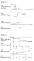
- APD By changing a bias voltage, APD has an ability to adjust a magnification of an electric current by receiving the light beam.
- the characteristics of the bias voltage and the output current of APD are shown in Fig. 7 .
- APD has a wide range of the magnification, and it can be 150 times or more.
- Va a certain level
- an avalanche phenomenon occurs. Therefore, in the adjustment of APD, the bias voltage is set to a value lower than the bias voltage to induce the avalanche while maintaining the needed magnification.
- a conventional type adjustment tool comprises a combination of an LED 22 for adjustment and a density filter 23.
- a light beam is emitted from the LED 22, of which output light amount is determined at a constant level, and it is projected toward the photodetection element 7 at a predetermined position.
- the emitted light beam is modulated in the same manner as the actual distance measuring light beam 4.
- APD directly receives the light beam from the LED 22, and the adjustment is made from a value obtained by photoelectric conversion.
- the magnification in this case is assumed as 1 x.
- a 1/150 density filter 23 is inserted between the photodetection element 7 and the LED 22.
- the photodetection light amount of the APD is turned to 1/150 of the initial value.
- the bias voltage is increased in such manner that the output current from APD is equalized to the value when the density filter 23 is not used.
- the magnification of 150 times is obtained.
- the distance measuring device has been re-adjusted periodically or after the use of a predetermined period of time.
- a special-purpose adjustment tool and a measuring instrument are required for the adjustment, and the user of the distance measuring device cannot perform adjustment as desired, and the re-adjustment has been usually requested to the manufacturer.
- complicated procedures are required each time the distance measuring device has to be sent back to the manufacturer for re-adjustment.
- the distance measuring device cannot be used during the re-adjustment, and this causes much inconvenience to the user.
- APD photodetection element
- the present invention provides a distance measuring device for measuring a distance based on a reflected distance measuring light beam from an object to be measured and on an internal reference light, comprising a first light emitting element (3) configured to emit a measuring light beam toward an object to be measured, and a photodetection unit (7) configured to receive the reflected measuring light beam reflected from said object to be measured, and means for directing light from the first light emitting element towards the photodetection unit (7) to be incident thereupon as the internal reference light; characterised by a photodetection sensitivity adjusting unit comprising:
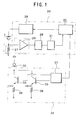
- Fig. 1 is a block diagram showing a photodetection sensitivity adjusting unit of a distance measuring device.
- the photodetection sensitivity adjusting unit comprises a gain control unit 24 and a light amount switching unit 38.
- the gain control unit 24 comprises a control unit 25, a bias circuit 26 where an output of a bias voltage is controlled by the control unit 25, a photodetection element 7 on which the bias voltage is applied by the bias circuit 26, a resistance 27 for adjusting a branched current value from the photodetection element 7, an amplifier 28 for amplifying the outputted branched current of the photodetection element 7, a peak-hold circuit 29 for holding a peak value of an output value from the amplifier 28, and an A/D converter 31 for converting the output value from the peak-hold circuit 29 to a digital signal.
- the light amount switching unit 38 is connected to a light emitting element 32 for adjustment and the control unit 25. Explanation will be given on the light amount switching unit 38.
- a first switching transistor 33 and a first resistance 34 are connected to the light emitting element 32 for adjustment.
- a second switching transistor 35 and a second resistance 36 are connected in parallel to the light emitting element 32 for adjustment.
- a resistance value (10 ⁇ in the figure) of the first resistance 34 is set to 1/10 of a resistance value (100 ⁇ in the figure) of the second resistance 36.
- a switching circuit 37 for applying an ON/OFF control voltage is connected to the first switching transistor 33 and the second switching transistor 35, and the switching circuit 37 is controlled by the control unit 25.
- An adjustment specifying light beam to be emitted from the light emitting element 32 for adjustment is designed to enter the photodetection element 7, and it has an optical system for magnification adjustment which is different from a distance measuring optical system shown in Fig. 6 .
- a magnification of the photodetection element 7 is adjusted after the distance measuring device has been used for a predetermined period of time or when a predetermined period of time has elapsed.
- Light emission of the light emitting element 3 is stopped, and a light beam is emitted from the light emitting element 32 for adjustment.
- the control voltage to the second switching transistor 35 is turned off, and the control voltage is applied on the first switching transistor 33.
- An initial driving current determined by the first resistance 34 flows to the adjustment light emitting element 32, and the adjustment light emitting element 32 emits the light beam.
- the reference bias voltage is applied on the photodetection element 7 by the bias circuit 26.
- the bias circuit 26 outputs an electric current which is determined by the reference bias voltage and by the light amount from the light emitting element 32 for adjustment.
- a reference peak value of the output current is detected by the peak-hold circuit 29 and the A/D converter 31, and this is inputted to the control unit 25.
- the control unit 25 stores this reference peak value in memory.
- a light amount switching command signal is issued from the control unit 25 to the switching circuit 37.
- the switching circuit 37 turns off the control voltage to the first switching transistor 33, and the control voltage is applied to the second switching transistor 35.
- a change driving current determined by the second resistance 36 flows to the adjustment light emitting element 32, and the light beam is emitted.
- the change driving current is 1/10 of the reference driving current, and the amount of the emitted light beam is attenuated to 1/10.
- the output current value from the photodetection element 7 under light attenuation is detected by the peak-hold circuit 29 and the A/D converter 31, and this is stored by the control unit 25 as a smallest magnification peak value.
- the control unit 25 issues a bias voltage increase signal to the bias circuit 26, and the bias circuit 26 increases the bias voltage applied on the photodetection element 7.
- the current value outputted by the photodetection element 7 is feedbacked to the control unit 25 from the peak-hold circuit 29 and the A/D converter 31, and the bias circuit 26 is controlled until the feedbacked output current reaches a value which is 15 times as high as the reference peak value.
- the control unit 25 stores the peak value at the moment when the output current of the photodetection element 7 reaches a value 15 times as high as the reference peak value as the highest magnification peak value, and the bias voltage at this moment is stored as the highest magnification bias voltage.
- the ratio of the lowest magnification peak value and the highest magnification peak value of the photodetection element 7 is 150 times.
- the photodetection sensitivity of the photodetection element 7 can be increased to 150 times.
- the magnification to be set is not limited to 150 times. If the peak value at the moment when the output current of the photodetection element 7 reaches a value 10 times as high as the reference peak value is stored as the highest magnification peak value, and if the bias voltage at this moment is stored as the highest magnification bias voltage, the photodetection sensitivity will be 100 times.
- the switching circuit 37 is separately provided, while it may be designed in such manner that, the amount of the emitted light beam from the light emitting element 3 may be changed by utilizing an internal reference light 12 and a reflected distance measuring light 4' which are emitted from the light emitting element 3.
- a photodetection sensitivity adjusting unit for this embodiment, the details of a photodetection sensitivity adjusting unit are not specifically given here.
- the circuit configuration is similar to that of the above embodiment. Three or more switching elements are connected in parallel to the light emitting element 32 for adjustment, and the light amount is switched by three steps or more by the switching circuit 37. In the following, description will be given referring to Fig. 1 .
- the light amount of the adjustment light emitting element 32 is decreased stepwise by the light amount switching unit 38.
- the bias circuit 26 is controlled by the control unit 25 in such manner that the output current of the photodetection element 7 in each step serves as a reference value, and the bias voltage is increased stepwise. Finally, the magnification of 150 times is obtained.
- the light beam of a predetermined light amount is emitted from the adjustment light emitting element 32.
- the output of the photodetection element 7 of the bias voltage in this case is assumed as a magnification of 1 x.
- the light amount is determined in advance from the characteristics of the photodetection element 7 as specified by the manufacturer.
- the bias voltage at this moment is very low and it is nearly 0 V.
- the output current value of the photodetection element 7 at this moment is sampled, and it is converted by A/D conversion. Then, a reference peak value is detected and it is stored by the control unit 25.
- the light amount switching unit 38 is controlled by the control unit 25, and the light amount of the adjustment light emitting element 32 is decreased to the light amount of the next step.
- the peak value detected from the output current of the photodetection element 7 is decreased in association with the light amount.
- the bias circuit 26 is controlled in such manner that the peak value will be equalized with the reference peak value, and the bias voltage is increased.
- the light amount of the adjustment light emitting element 32 is decreased and the bias voltage is increased so that the peak value is equalized with the reference peak value. This procedure is repeated, and the adjustment is completed when the magnification ultimately reaches the predetermined magnification value, i.e. 150 times.
- the light amount is electrically switched, while the light amount may be optically switched using a density filter. It may be designed in such manner that a reflection prism 6 is placed at a predetermined position with respect to the distance measuring device, and the light amount received by the photodetection element 7 may be switched by utilizing the reflected distance measuring light 4' and the density filter 20.
- the present invention provides a distance measuring device, which comprises a light emitting unit for emitting a distance measuring light beam to an object to be measured and a photodetection element for receiving a reflected measuring light beam reflected from the object to be measured.
- the light emitting unit can project the light beam of a plurality of values of specified light amount to the photodetection element, and a range of photodetection sensitivity of the photodetection element is determined in response to a change of the light amount.
- the sensitivity of the photodetection element APD
- This makes it possible to design a system in a simple structure and to perform an adjustment in an easy manner. Also, it is possible to eliminate the complicated procedures for the re-adjustment and to exclude the limitation on the use of the distance measuring device for the purpose of the re-adjustment.
Claims (4)
- Abstandsmessgerät zum Messen eines Abstandes auf der Basis eines von einem zu messenden Objekt reflektierten Abstandsmesslichtstrahls und eines internen Bezugslichts, das ein erstes lichtemittierendes Element (3), das dafür konfiguriert ist, einen Messlichtstrahl zu einem zu messenden Objekt zu emittieren, und eine Photodetektionseinheit (7), die dafür konfiguriert ist, den von dem zu messenden Objekt reflektierten Messlichtstrahl zu empfangen, und Mittel zum Lenken von Licht aus dem ersten lichtemittierenden Element zu der Photodetektionseinheit (7), dass es darauf als das interne Bezugslicht einfällt, aufweist;
gekennzeichnet durch eine Photodetektions-Empfindlichkeitsanpassungseinheit, die aufweist:ein zweites lichtemittierendes Element (32), das dafür konfiguriert ist, Anpassungslicht an die Photodetektionseinheit (7) zu emittieren, nachdem das Abstandsmessgerät für eine vorbestimmte Zeitdauer benutzt worden ist, oder wenn eine vorbestimmte Zeitdauer verstrichen ist, und die Lichtemission des ersten lichtemittierenden Elementes (3) angehalten ist;eine Lichtmengenumschalteinheit (38), die dafür konfiguriert ist, die Menge von dem vom zweiten lichtemittierenden Element (32) emittierten Anpassungslicht zu steuern, sodass sie sequentiell jede von mehreren Stufen vorbestimmter Anpassungslichtmengen annimmt;eine Verstärkungssteuerungseinheit, die dafür konfiguriert ist, die Vorspannung der Photodetektionseinheit (7) in Reaktion auf eine Veränderung in der Anpassungslichtmenge dergestalt zu verändern, dass die Photodetektionsempfindlichkeit der Photodetektionseinheit (7) verändert wird, um somit ein Ausgangssignal der Photodetektionseinheit (7) einen vorbestimmten Wert annehmen zu lassen. - Verfahren zum Anpassen der Photodetektionsempfindlichkeit einer Photodetektionseinheit (7) eines Abstandsmessgerätes des Typs, in welchem ein Abstand auf der Basis eines von einem zu messenden Objekt reflektierten Abstandsmesslichtes und eines internen Bezugslichtes gemessen werden kann, indem Licht aus einem ersten lichtemittierenden Element (3) auf ein zu messendes Objekt projiziert wird, reflektiertes Licht von dem Objekt bei einer Photodetektionseinheit (7) des Gerätes als der reflektierte Abstandsmesslichtstrahl gemessen wird, wobei das Gerät Mittel zum Lenken von Licht aus dem ersten lichtemittierenden Element (3) zu der Photodetektionseinheit (7) hat, dass es darauf als das interne Bezugslicht einfällt, wobei das Verfahren die Schritte aufweist:Lenken eines Anpassungslichtes aus einem zweiten lichtemittierenden Element (32) auf die Photodetektionseinheit (7), nachdem das Abstandsmessgerät für eine vorbestimmte Zeitdauer benutzt worden ist, oder wenn eine vorbestimmte Zeitdauer verstrichen ist, und die Lichtemission des ersten lichtemittierenden Elementes (3) angehalten ist, und Messen des Ausgangssignals der Photodetektionseinheit (7);sequentielles Verändern des von dem zweiten lichtemittierenden Element (32) emittierten Anpassungslichtes, dass es mehrere Stufen vorbestimmter Anpassungslichtmengen annimmt; undVerändern der Vorspannung der Photodetektionseinheit (7) in Reaktion auf eine Veränderung in der Anpassungslichtmenge dergestalt, dass die Photodetektionsempfindlichkeit der Photodetektionseinheit (7) verändert wird, um somit ein Ausgangssignal der Photodetektionseinheit (7) einen vorbestimmten Wert annehmen zu lassen.
- Verfahren nach Anspruch 2, wobei das zweite lichtemittierende Element (32) Licht bei einer vorbestimmten Verstärkung auf eine vorbestimmte Anpassungslichtmenge abschwächt, und eine Vorspannung in einer solchen Weise ermittelt wird, dass eine Empfindlichkeit einer vorbestimmten Verstärkung der Photodetektionseinheit (7) gemäß einem Lichtabschwächungszustand erzielt werden kann.
- Verfahren nach Anspruch 2, wobei die von dem zweiten lichtemittierenden Element (32) emittierte vorbestimmte Anpassungslichtmenge sequentiell in mehreren Stufen verringert wird und die Vorspannung bei jeder Stufe erhöht wird, um das Ausgangssignal der Photodetektionseinheit auf einem vorbestimmten Wert zu halten, und wobei die Anpassung beendet wird, wenn ein Verstärkungswert der Photodetektionseinheit (7) einen vorbestimmten Verstärkungswert erreicht.
Applications Claiming Priority (2)
| Application Number | Priority Date | Filing Date | Title |
|---|---|---|---|
| JP34726699 | 1999-12-07 | ||
| JP34726699A JP4630413B2 (ja) | 1999-12-07 | 1999-12-07 | 距離測定機及び距離測定機の受光部調整方法 |
Publications (3)
| Publication Number | Publication Date |
|---|---|
| EP1106963A2 EP1106963A2 (de) | 2001-06-13 |
| EP1106963A3 EP1106963A3 (de) | 2003-08-06 |
| EP1106963B1 true EP1106963B1 (de) | 2014-07-02 |
Family
ID=18389062
Family Applications (1)
| Application Number | Title | Priority Date | Filing Date |
|---|---|---|---|
| EP00310876.8A Expired - Lifetime EP1106963B1 (de) | 1999-12-07 | 2000-12-07 | Abstandsmessgerät und Verfahren zur Regelung der Photodetektoreinheit |
Country Status (3)
| Country | Link |
|---|---|
| US (1) | US6693703B2 (de) |
| EP (1) | EP1106963B1 (de) |
| JP (1) | JP4630413B2 (de) |
Families Citing this family (7)
| Publication number | Priority date | Publication date | Assignee | Title |
|---|---|---|---|---|
| US6762846B1 (en) | 2002-09-19 | 2004-07-13 | Nanometrics Incorporated | Substrate surface profile and stress measurement |
| US20050230605A1 (en) * | 2004-04-20 | 2005-10-20 | Hamid Pishdadian | Method of measuring using a binary optical sensor |
| JP4855749B2 (ja) * | 2005-09-30 | 2012-01-18 | 株式会社トプコン | 距離測定装置 |
| JP2008270558A (ja) * | 2007-04-20 | 2008-11-06 | Sumitomo Electric Ind Ltd | 光受信モジュールの調整方法 |
| JP6045963B2 (ja) * | 2013-04-05 | 2016-12-14 | 日立マクセル株式会社 | 光測距装置 |
| JP7476583B2 (ja) | 2020-03-11 | 2024-05-01 | 株式会社デンソー | 測定装置 |
| CN116324508A (zh) * | 2020-08-17 | 2023-06-23 | 北京航迹科技有限公司 | 激光雷达系统的动态接收器增益控制 |
Citations (3)
| Publication number | Priority date | Publication date | Assignee | Title |
|---|---|---|---|---|
| US4274736A (en) * | 1978-10-11 | 1981-06-23 | Kern & Co. Ag | Method and apparatus for electrooptical distance measurement |
| US5396510A (en) * | 1993-09-30 | 1995-03-07 | Honeywell Inc. | Laser sensor capable of measuring distance, velocity, and acceleration |
| JPH0854468A (ja) * | 1994-08-10 | 1996-02-27 | Nikon Corp | 受光器 |
Family Cites Families (8)
| Publication number | Priority date | Publication date | Assignee | Title |
|---|---|---|---|---|
| US3815994A (en) * | 1972-03-31 | 1974-06-11 | Kaman Sciences Corp | System and method for measuring distance |
| SE382507B (sv) * | 1974-06-05 | 1976-02-02 | Aga Ab | Sett att reglera forsterkningen i en stralningsdetekterande lavindiod. |
| US4464048A (en) * | 1981-03-25 | 1984-08-07 | Barr & Stroud Limited | Laser rangefinders |
| JPS60149929A (ja) * | 1984-11-26 | 1985-08-07 | Tokyo Optical Co Ltd | アバランシエ.ダイオードの温度補償装置 |
| JPH0346588A (ja) * | 1989-07-13 | 1991-02-27 | Mitsubishi Electric Corp | レーザ受信器 |
| JP2951547B2 (ja) * | 1994-10-03 | 1999-09-20 | 浜松ホトニクス株式会社 | 光波距離計および距離測定方法 |
| US5691808A (en) * | 1995-07-31 | 1997-11-25 | Hughes Electronics | Laser range finder receiver |
| DE19643287A1 (de) * | 1996-10-21 | 1998-04-23 | Leica Ag | Verfahren und Vorrichtung zur Kalibrierung von Entfernungsmeßgeräten |
-
1999
- 1999-12-07 JP JP34726699A patent/JP4630413B2/ja not_active Expired - Fee Related
-
2000
- 2000-11-29 US US09/726,143 patent/US6693703B2/en not_active Expired - Lifetime
- 2000-12-07 EP EP00310876.8A patent/EP1106963B1/de not_active Expired - Lifetime
Patent Citations (3)
| Publication number | Priority date | Publication date | Assignee | Title |
|---|---|---|---|---|
| US4274736A (en) * | 1978-10-11 | 1981-06-23 | Kern & Co. Ag | Method and apparatus for electrooptical distance measurement |
| US5396510A (en) * | 1993-09-30 | 1995-03-07 | Honeywell Inc. | Laser sensor capable of measuring distance, velocity, and acceleration |
| JPH0854468A (ja) * | 1994-08-10 | 1996-02-27 | Nikon Corp | 受光器 |
Also Published As
| Publication number | Publication date |
|---|---|
| US6693703B2 (en) | 2004-02-17 |
| JP2001165654A (ja) | 2001-06-22 |
| JP4630413B2 (ja) | 2011-02-09 |
| US20010002860A1 (en) | 2001-06-07 |
| EP1106963A3 (de) | 2003-08-06 |
| EP1106963A2 (de) | 2001-06-13 |
Similar Documents
| Publication | Publication Date | Title |
|---|---|---|
| JP4709931B2 (ja) | 距離測定装置および距離測定方法 | |
| EP1883786B1 (de) | Bordlichtquelle auf basis einer verstärkungskorrektur für halbaktive lasersucher | |
| US5148233A (en) | Optical attenuator and optical power meter calibration systems with optical-pulse conversion and averaging | |
| US8792088B2 (en) | Distance-measuring system | |
| US6288775B1 (en) | Lightwave distance measuring apparatus and method | |
| JPH1123709A (ja) | 距離測定装置 | |
| US7872735B2 (en) | Method and apparatus for referencing a MEMS device | |
| EP1106963B1 (de) | Abstandsmessgerät und Verfahren zur Regelung der Photodetektoreinheit | |
| US4488813A (en) | Reflectivity compensating system for fiber optic sensor employing dual probes at a fixed gap differential | |
| CN112219135A (zh) | 一种测距装置、测距方法以及移动平台 | |
| US10802221B1 (en) | Dynamically optimized tunable filters for optical sensing systems | |
| JP2006329797A (ja) | 光波距離計 | |
| CN111492261A (zh) | 一种激光接收电路及测距装置、移动平台 | |
| JP2016191630A (ja) | 光波距離計 | |
| US5239353A (en) | Optical distance measuring apparatus | |
| JP2552325Y2 (ja) | 光波測距装置 | |
| US5309072A (en) | Distance measurement apparatus for camera, and distance measurement method | |
| JP2002324909A (ja) | 光電変換回路及びレーザ測距装置 | |
| JPH09281237A (ja) | レーザ測距装置 | |
| JPH06258436A (ja) | 光波距離計 | |
| JPH0712985U (ja) | 光波測距装置 | |
| JP2006086431A (ja) | 波長可変光源および波長特性測定システム | |
| JPH0672925B2 (ja) | レーザ測距装置 | |
| JPH0421123B2 (de) | ||
| JPH06230129A (ja) | 光波距離計 |
Legal Events
| Date | Code | Title | Description |
|---|---|---|---|
| PUAI | Public reference made under article 153(3) epc to a published international application that has entered the european phase |
Free format text: ORIGINAL CODE: 0009012 |
|
| AK | Designated contracting states |
Kind code of ref document: A2 Designated state(s): AT BE CH CY DE DK ES FI FR GB GR IE IT LI LU MC NL PT SE TR |
|
| AX | Request for extension of the european patent |
Free format text: AL;LT;LV;MK;RO;SI |
|
| PUAL | Search report despatched |
Free format text: ORIGINAL CODE: 0009013 |
|
| AK | Designated contracting states |
Designated state(s): AT BE CH CY DE DK ES FI FR GB GR IE IT LI LU MC NL PT SE TR |
|
| AX | Request for extension of the european patent |
Extension state: AL LT LV MK RO SI |
|
| RIC1 | Information provided on ipc code assigned before grant |
Ipc: 7G 01S 17/08 B Ipc: 7G 01S 7/48 B Ipc: 7G 01C 3/08 A |
|
| 17P | Request for examination filed |
Effective date: 20031125 |
|
| AKX | Designation fees paid |
Designated state(s): CH DE LI SE |
|
| 17Q | First examination report despatched |
Effective date: 20080624 |
|
| GRAP | Despatch of communication of intention to grant a patent |
Free format text: ORIGINAL CODE: EPIDOSNIGR1 |
|
| GRAJ | Information related to disapproval of communication of intention to grant by the applicant or resumption of examination proceedings by the epo deleted |
Free format text: ORIGINAL CODE: EPIDOSDIGR1 |
|
| INTG | Intention to grant announced |
Effective date: 20140108 |
|
| GRAP | Despatch of communication of intention to grant a patent |
Free format text: ORIGINAL CODE: EPIDOSNIGR1 |
|
| INTG | Intention to grant announced |
Effective date: 20140129 |
|
| GRAS | Grant fee paid |
Free format text: ORIGINAL CODE: EPIDOSNIGR3 |
|
| GRAA | (expected) grant |
Free format text: ORIGINAL CODE: 0009210 |
|
| AK | Designated contracting states |
Kind code of ref document: B1 Designated state(s): CH DE LI SE |
|
| REG | Reference to a national code |
Ref country code: CH Ref legal event code: EP Ref country code: CH Ref legal event code: NV Representative=s name: FIAMMENGHI-FIAMMENGHI, CH |
|
| REG | Reference to a national code |
Ref country code: DE Ref legal event code: R096 Ref document number: 60048638 Country of ref document: DE Effective date: 20140814 |
|
| REG | Reference to a national code |
Ref country code: SE Ref legal event code: TRGR |
|
| REG | Reference to a national code |
Ref country code: DE Ref legal event code: R097 Ref document number: 60048638 Country of ref document: DE |
|
| PLBE | No opposition filed within time limit |
Free format text: ORIGINAL CODE: 0009261 |
|
| STAA | Information on the status of an ep patent application or granted ep patent |
Free format text: STATUS: NO OPPOSITION FILED WITHIN TIME LIMIT |
|
| 26N | No opposition filed |
Effective date: 20150407 |
|
| PGFP | Annual fee paid to national office [announced via postgrant information from national office to epo] |
Ref country code: SE Payment date: 20151211 Year of fee payment: 16 |
|
| REG | Reference to a national code |
Ref country code: SE Ref legal event code: EUG |
|
| PG25 | Lapsed in a contracting state [announced via postgrant information from national office to epo] |
Ref country code: SE Free format text: LAPSE BECAUSE OF NON-PAYMENT OF DUE FEES Effective date: 20161208 |
|
| PGFP | Annual fee paid to national office [announced via postgrant information from national office to epo] |
Ref country code: DE Payment date: 20171129 Year of fee payment: 18 |
|
| PGFP | Annual fee paid to national office [announced via postgrant information from national office to epo] |
Ref country code: CH Payment date: 20171212 Year of fee payment: 18 |
|
| REG | Reference to a national code |
Ref country code: DE Ref legal event code: R119 Ref document number: 60048638 Country of ref document: DE |
|
| REG | Reference to a national code |
Ref country code: CH Ref legal event code: PL |
|
| PG25 | Lapsed in a contracting state [announced via postgrant information from national office to epo] |
Ref country code: DE Free format text: LAPSE BECAUSE OF NON-PAYMENT OF DUE FEES Effective date: 20190702 |
|
| PG25 | Lapsed in a contracting state [announced via postgrant information from national office to epo] |
Ref country code: LI Free format text: LAPSE BECAUSE OF NON-PAYMENT OF DUE FEES Effective date: 20181231 Ref country code: CH Free format text: LAPSE BECAUSE OF NON-PAYMENT OF DUE FEES Effective date: 20181231 |