EP1106718A1 - Luftleitkasten - Google Patents
Luftleitkasten Download PDFInfo
- Publication number
- EP1106718A1 EP1106718A1 EP00122659A EP00122659A EP1106718A1 EP 1106718 A1 EP1106718 A1 EP 1106718A1 EP 00122659 A EP00122659 A EP 00122659A EP 00122659 A EP00122659 A EP 00122659A EP 1106718 A1 EP1106718 A1 EP 1106718A1
- Authority
- EP
- European Patent Office
- Prior art keywords
- air guide
- guide box
- plastic body
- box according
- plastic
- Prior art date
- Legal status (The legal status is an assumption and is not a legal conclusion. Google has not performed a legal analysis and makes no representation as to the accuracy of the status listed.)
- Granted
Links
- 238000009960 carding Methods 0.000 claims abstract description 7
- 239000004033 plastic Substances 0.000 claims description 31
- 229920000049 Carbon (fiber) Polymers 0.000 claims description 14
- 239000004917 carbon fiber Substances 0.000 claims description 14
- 230000015572 biosynthetic process Effects 0.000 claims description 11
- 239000000835 fiber Substances 0.000 claims description 8
- 239000002657 fibrous material Substances 0.000 claims description 8
- 229910010293 ceramic material Inorganic materials 0.000 claims description 4
- 239000002131 composite material Substances 0.000 claims description 4
- 239000004760 aramid Substances 0.000 claims description 2
- 229920006231 aramid fiber Polymers 0.000 claims description 2
- 239000006260 foam Substances 0.000 claims description 2
- 239000000463 material Substances 0.000 abstract description 6
- 229920002430 Fibre-reinforced plastic Polymers 0.000 abstract 1
- 239000011151 fibre-reinforced plastic Substances 0.000 abstract 1
- 238000004519 manufacturing process Methods 0.000 description 7
- 239000003822 epoxy resin Substances 0.000 description 4
- 239000008187 granular material Substances 0.000 description 4
- 239000004745 nonwoven fabric Substances 0.000 description 4
- 229920000647 polyepoxide Polymers 0.000 description 4
- 239000000843 powder Substances 0.000 description 4
- 238000013016 damping Methods 0.000 description 2
- 239000000654 additive Substances 0.000 description 1
- 239000004918 carbon fiber reinforced polymer Substances 0.000 description 1
- 239000007795 chemical reaction product Substances 0.000 description 1
- 239000004744 fabric Substances 0.000 description 1
- 239000012467 final product Substances 0.000 description 1
- 239000003292 glue Substances 0.000 description 1
- 239000007769 metal material Substances 0.000 description 1
- VNWKTOKETHGBQD-UHFFFAOYSA-N methane Chemical compound C VNWKTOKETHGBQD-UHFFFAOYSA-N 0.000 description 1
- 239000002245 particle Substances 0.000 description 1
- 230000002787 reinforcement Effects 0.000 description 1
- 208000024891 symptom Diseases 0.000 description 1
Images


Classifications
-
- D—TEXTILES; PAPER
- D01—NATURAL OR MAN-MADE THREADS OR FIBRES; SPINNING
- D01G—PRELIMINARY TREATMENT OF FIBRES, e.g. FOR SPINNING
- D01G15/00—Carding machines or accessories; Card clothing; Burr-crushing or removing arrangements associated with carding or other preliminary-treatment machines
- D01G15/02—Carding machines
- D01G15/12—Details
- D01G15/46—Doffing or like arrangements for removing fibres from carding elements; Web-dividing apparatus; Condensers
- D01G15/465—Doffing arrangements for removing fibres using, or cooperating with, pneumatic means
Definitions
- the invention relates to an air guide box, which - viewed in cross section - in is essentially wedge-shaped for a carding machine.
- Such a control box is known from DE 33 15 839 C2.
- Carding machines are used for the production of nonwovens from fibrous materials and have several pairs of rollers, the rollers of the pairs of rollers during the production of fleece at high speeds around its own axis rotate.
- the rotation of the rollers results in the fleece formation triangle of a pair of rolls of turbulence caused by the arrangement of the Air guide box in the fleece formation triangle and its design targeted can be used to determine the nature of the final product and thereby beneficially influencing its properties.
- the invention has for its object an air guide box at the beginning mentioned type to develop such that this is a very large Has dimensional stability even with a very long length and therefore with a correspondingly long pair of rollers or a correspondingly long one Roller can be used and that the gap dimensions between the Air guide box and the pair of rollers or the roller over their entire Length are consistently accurate and closely tolerated.
- the air guide box through a plastic body is formed.
- the advantage here is that the Air guide box, even with long lengths, compared to air guide boxes that consist of a metallic material, only a low weight has, so that, for example, a weight-related deflection of the Luftleitkastens between his bearings during the Intended use of the carding machine safely. is excluded. Due to the low weight of the air guide box its storage is significantly simplified and it is only a small one Adjustment power required to position the air control box in its relative position to the pair of rollers to adjust in a short time. The gaps between the Surfaces of the guide box and the roller pair can because of the low weight and great dimensional stability of the air guide box if necessary, be chosen very small.
- Nonwovens are characterized by a, even with very large web widths particularly uniform texture.
- the air guide box can be in a fleece formation triangle of a pair of rollers of a carding machine arranged or assigned to a single roller.
- a plastic body has particularly advantageous usage properties on, which consists of a composite fiber material.
- a Composite fiber material made of fiber-reinforced epoxy resin has the advantage that distinguish themselves through the use of this high-strength material thin-walled air guide boxes with an excellent one mechanical and dynamic resistance.
- the thermal stability of the air guide box results from the use of fiber reinforced materials, making the gap setting as constant can be viewed.
- a combination of fibers is preferred Carbon fibers and aramid fibers for use.
- the carbon fibers can be in the form of fiber strands or fabrics or a prepreg embedded in the plastic. Through this configuration and / or in that the carbon fibers in a prestressed state in the plastic are embedded, there is a further improvement in mechanical and dynamic properties of the air guide box. Next good flexural strength can result in good damping of Natural vibrations can be achieved, which is producing an even one procured fleece favored. Natural vibrations of the air guide box can, for example, by the air turbulence and / or the Vibrations of the roller pair are excited when the rollers rotate.
- the carbon fibers preferably extend essentially in Axial direction of the pair of rollers, the carbon fibers are biased to deflect between its bearings in Counteract the direction of the nip.
- the one facing the nip of the pair of rollers, in the nonwoven triangle arranged front edge of the plastic body is preferably by a separately produced, wear-resistant ledge formed, which has a higher resistance against abrasive wear than the rest of the plastic body. This keeps the shape of the leading edge for a long time Preserve service life even if, for example, for the production of nonwovens not just fibrous materials but also powder, for example or granules are introduced into the nonwoven formation triangle in order to produce the To provide the fleece with the required properties.
- the powder or granules can have a greater hardness than that Have fiber itself.
- the front edge is particularly wear-resistant when the bar is made from one ceramic material.
- the bar can be non-positively and / or positively with the plastic body be connected.
- the bar can be placed in a dovetail-shaped undercut of the plastic body insert and / or glue in the undercut.
- advantageous performance characteristics is Plastic body preferably hollow. Inside the cavity If necessary, reinforcements such as CFRP rods be arranged, the forces introduced into the air guide box at least partially absorbed by the bars.
- the Possibility that the plastic body has a compressed air connection can have and air outlet openings at least in the direction of one Nip-limiting roller.
- the turbulence in the fleece triangle can be influenced directly and advantageously.
- the compressed air additives for example in the form of particles, in order to the performance characteristics and / or the nature of the to be manufactured to the respective circumstances of the To be able to adapt the application better.
- the Plastic body is at least partially filled with a foam.
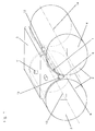
- a pair of rollers 2 of a carding machine is shown, the Roll pair 2 is formed by the rolls 3 and 4.
- the two rollers 3, 4 each rotate about their axes 13, 14, the direction of rotation of the rollers, depending on the respective Manufacturing process, in the same direction or in opposite directions to each other.
- the air guide box 5 is in the fleece formation triangle 1 of the pair of rollers 2 arranged and consists of a plastic body 5.
- a plastic body 5 Carbon fibers 6 reinforced epoxy resin, the Carbon fibers 6 in the form of fiber strands 7 in the plastic are embedded.
- the front edge 9 of the plastic body 5 is produced by a separately Formed bar 10, which consists of a ceramic material and therefore extremely good resistance to abrasive wear having.
- the plastic body 5 protrudes with its front edge 9 in the Roller gap 8 of the roller pair 2, the air guide box in the here
- the exemplary embodiments shown are provided with a compressed air connection 12 is to have additional influence on those in the fleece formation triangle turbulence and / or around the To be able to add powder or granules to fibrous materials as required.
- FIG. 2 the air guide box from Fig. 1 is a cross-sectional view shown.
- the epoxy resin reinforced with carbon fibers 6 forms one high-strength material, which is therefore particularly thin-walled can be an excellent and despite its light weight Has dimensional stability.
- the detail x from FIG. 2 is enlarged shown.
- the strip 10, which consists of a ceramic material, is in this embodiment, non-positively and positively with the Plastic body 5 connected.
- the bar 10 is in cross section in essentially dovetail-shaped and congruent designed recess of the plastic body 5 enclosed.
- the leading edge 9 of such an air guide box is particularly durable.
- Fig. 3 the air guide box from Fig. 1 is shown as a single part.
- the fiber materials further Materials such as powders or granules to feed the Use properties of the nonwoven fabric better to the to be able to adapt to the respective circumstances of the application.
- the materials mixed with the blown air flow pass through the Air outlet openings 12 together with the compressed air in the Fleece formation triangle 1 and later form part of the fleece.
- Fig. 4 is the air guide box of Fig. 1 in a longitudinal section shown.
- the plastic body 5 is hollow and consists of Carbon fiber 6 reinforced epoxy resin.
- the fiber strands 7 are in pre-stressed state embedded in the plastic. This results in a further improvement in mechanical and dynamic Characteristics of the air guide box. In addition to good flexural strength thereby good damping of natural vibrations can be achieved favors the production of a uniformly procured fleece.
- the Carbon fibers 6 extend essentially in the axial direction of the Roller pairs 2, the carbon fibers 6 or fiber strands 7 such are biased to deflect between the bearings of the Counteract air guide box in the direction of the nip 8.
Landscapes
- Engineering & Computer Science (AREA)
- Textile Engineering (AREA)
- Preliminary Treatment Of Fibers (AREA)
- Valve-Gear Or Valve Arrangements (AREA)
- Air Bags (AREA)
- Magnetic Bearings And Hydrostatic Bearings (AREA)
Abstract
Description
- Fig. 1
- einen Luftleitkasten, der im Vliesbildungsdreieck eines Walzenpaars angeordnet ist,
- Fig. 2
- den Luftleitkasten aus Fig. 1 in quergeschnittener Darstellung,
- Fig. 3
- den Luftleitkasten aus Fig. 1 als Einzelteil und
- Fig. 4
- einen Längsschnitt durch den Luftleitkasten aus Fig. 1.
Claims (11)
- Luftleitkasten, der - im Querschnitt betrachtet - im wesentlichen keilförmig ausgebildet ist, für eine Krempelmaschine, dadurch gekennzeichnet, daß der Luftleitkasten durch einen Kunststoffkörper (5) gebildet ist.
- Luftleitkasten nach Anspruch 1, dadurch gekennzeichnet, daß der Kunststoffkörper (5) aus einem Verbundfaserwerkstoff besteht.
- Luftleitkasten nach einem der Ansprüche 1 oder 2, dadurch gekennzeichnet, daß der Verbundfaserwerkstoff aus einer Kombination von Kohlenstoffasern (6) und Aramidfasern besteht.
- Luftleitkasten nach einem der Ansprüche 1 bis 3, dadurch gekennzeichnet, daß die Kohlenstoffasern (6) in Form von Fasersträngen (7) in den Kunststoff eingebettet sind.
- Luftleitkasten nach einem der Ansprüche 1 bis 4, dadurch gekennzeichnet, daß die Kohlenstoffasern (6) in vorgespanntem Zustand in den Kunststoff eingebettet sind.
- Luftleitkasten nach einem der Ansprüche 1 bis 5, dadurch gekennzeichnet, daß die dem Walzenspalt (8) des Walzenpaars (2, 3, 4) zugewandte, im Vliesbildungsdreieck (1) angeordnete Vorderkante (9) des Kunststoffkörpers (5) durch eine separat erzeugte, verschleißfeste Leiste (10) gebildet ist, die eine höhere Beständigkeit gegen abrasiven Verschleiß aufweist, als der übrige Kunststoffkörper (5).
- Luftleitkasten nach Anspruch 6, dadurch gekennzeichnet, daß die Leiste (10) aus einem keramischen Werkstoff besteht.
- Luftleitkasten nach einem der Ansprüche 6 oder 7, dadurch gekennzeichnet, daß die Leiste (10) kraft- und / oder formschlüssig mit dem Kunststoffkörper (5) verbunden ist.
- Luftleitkasten nach einem der Ansprüche 1 bis 8, dadurch gekennzeichnet, daß der Kunststoffkörper (5) hohl ausgebildet ist.
- Luftleitkasten nach Anspruch 9, dadurch gekennzeichnet, daß der Kunststoffkörper (5) einen Druckluftanschluß (11) aufweist und mit Luftaustrittsöffnungen (12) zumindest in Richtung einer der den Walzenspalt (8) begrenzenden Walzen (3, 4) versehen ist.
- Luftleitkasten nach einem der Ansprüche 1 bis 8, dadurch gekennzeichnet, daß der Kunststoffkörper (5) mit einem Schaum zumindest teilweise ausgefüllt ist.
Applications Claiming Priority (2)
| Application Number | Priority Date | Filing Date | Title |
|---|---|---|---|
| DE19958349 | 1999-12-03 | ||
| DE19958349A DE19958349C1 (de) | 1999-12-03 | 1999-12-03 | Luftleitkasten |
Publications (2)
| Publication Number | Publication Date |
|---|---|
| EP1106718A1 true EP1106718A1 (de) | 2001-06-13 |
| EP1106718B1 EP1106718B1 (de) | 2003-12-17 |
Family
ID=7931320
Family Applications (1)
| Application Number | Title | Priority Date | Filing Date |
|---|---|---|---|
| EP00122659A Expired - Lifetime EP1106718B1 (de) | 1999-12-03 | 2000-10-18 | Luftleitkasten |
Country Status (3)
| Country | Link |
|---|---|
| EP (1) | EP1106718B1 (de) |
| AT (1) | ATE256772T1 (de) |
| DE (2) | DE19958349C1 (de) |
Cited By (1)
| Publication number | Priority date | Publication date | Assignee | Title |
|---|---|---|---|---|
| FR2859224A1 (fr) * | 2003-08-08 | 2005-03-04 | Dilo Kg Maschf Oskar | Auge de guidage de voile pour une cardeuse a cylindres |
Families Citing this family (1)
| Publication number | Priority date | Publication date | Assignee | Title |
|---|---|---|---|---|
| CN115505238B (zh) * | 2022-09-17 | 2024-04-26 | 嘉兴翔翌复合材料有限公司 | 一种碳纤维rs4风箱导管及其制备方法 |
Citations (5)
| Publication number | Priority date | Publication date | Assignee | Title |
|---|---|---|---|---|
| US3665846A (en) * | 1971-01-11 | 1972-05-30 | Jurgen Schiunke | Protective shield for use at the bite of rollers for paper and textile calenders |
| DE3346335A1 (de) * | 1983-12-22 | 1985-07-18 | Hergeth Hollingsworth GmbH, 4408 Dülmen | Verfahren und vorrichtung zur herstellung einer gleichmaessigen faservliesbildung in der vliesbildungszone zwischen tambour und faseruebernahmeorgan |
| DE3315839C1 (de) * | 1983-04-30 | 1990-09-13 | Spinnbau GmbH, 2820 Bremen | Krempel oder Karde |
| US5427020A (en) * | 1993-06-05 | 1995-06-27 | Sulzer Papertec Krefeld Gmbh | Finger-protection device for a roller gap |
| DE19743744A1 (de) * | 1997-10-02 | 1999-04-08 | Schlafhorst & Co W | Schaft zur Lagerung und zum Antrieb eines Offenend-Spinnrotors |
-
1999
- 1999-12-03 DE DE19958349A patent/DE19958349C1/de not_active Expired - Fee Related
-
2000
- 2000-10-18 DE DE50004784T patent/DE50004784D1/de not_active Expired - Lifetime
- 2000-10-18 AT AT00122659T patent/ATE256772T1/de active
- 2000-10-18 EP EP00122659A patent/EP1106718B1/de not_active Expired - Lifetime
Patent Citations (5)
| Publication number | Priority date | Publication date | Assignee | Title |
|---|---|---|---|---|
| US3665846A (en) * | 1971-01-11 | 1972-05-30 | Jurgen Schiunke | Protective shield for use at the bite of rollers for paper and textile calenders |
| DE3315839C1 (de) * | 1983-04-30 | 1990-09-13 | Spinnbau GmbH, 2820 Bremen | Krempel oder Karde |
| DE3346335A1 (de) * | 1983-12-22 | 1985-07-18 | Hergeth Hollingsworth GmbH, 4408 Dülmen | Verfahren und vorrichtung zur herstellung einer gleichmaessigen faservliesbildung in der vliesbildungszone zwischen tambour und faseruebernahmeorgan |
| US5427020A (en) * | 1993-06-05 | 1995-06-27 | Sulzer Papertec Krefeld Gmbh | Finger-protection device for a roller gap |
| DE19743744A1 (de) * | 1997-10-02 | 1999-04-08 | Schlafhorst & Co W | Schaft zur Lagerung und zum Antrieb eines Offenend-Spinnrotors |
Cited By (1)
| Publication number | Priority date | Publication date | Assignee | Title |
|---|---|---|---|---|
| FR2859224A1 (fr) * | 2003-08-08 | 2005-03-04 | Dilo Kg Maschf Oskar | Auge de guidage de voile pour une cardeuse a cylindres |
Also Published As
| Publication number | Publication date |
|---|---|
| EP1106718B1 (de) | 2003-12-17 |
| DE19958349C1 (de) | 2001-02-15 |
| ATE256772T1 (de) | 2004-01-15 |
| DE50004784D1 (de) | 2004-01-29 |
Similar Documents
| Publication | Publication Date | Title |
|---|---|---|
| DE2620118C3 (de) | Vorrichtung zum Spinnen von Fasergarn | |
| DE4440079C2 (de) | Mehrschichten-Stoffauflauf | |
| EP1953275B1 (de) | Streckwerk mit Verdichtungszone | |
| DE10229834A1 (de) | Streckwerk für Spinnmaschinen mit nachgeordneter Verdichtungsvorrichtung | |
| EP2390390B1 (de) | Verdichterrahmen in einem Streckwerk zum Verziehen eines Faserbandes | |
| WO2017187293A1 (de) | Luftspinnmaschine sowie verfahren zur herstellung eines garns | |
| DE102005035049A1 (de) | Spinnvorrichtung zur Herstellung eines gesponnenen Fadens mittels eines umlaufenden Luftstroms | |
| EP1335050B1 (de) | Textilverarbeitungsmaschine mit einem Faserförderkanal und einer Faserführungsfläche | |
| EP1106718B1 (de) | Luftleitkasten | |
| DE10104182B4 (de) | Transportband zum Transportieren eines zu verdichtenden Faserverbandes | |
| EP1921184A2 (de) | Luntenführer für ein Streckwerk | |
| DE19628164B4 (de) | Verstellbarer Vliesführer | |
| CH662134A5 (de) | Spinnvorrichtung. | |
| DE102006062364B4 (de) | Vorrichtung zum Herstellen einer Maschenware | |
| DE4318773C1 (de) | Fingerschutzvorrichtung für einen Walzenspalt | |
| EP2886688B1 (de) | Einsatz und Spinnmaschine | |
| EP3688209B1 (de) | Verdichtereinrichtung | |
| EP1975288A2 (de) | Spinnmaschine | |
| DE19528727C2 (de) | Offen-End-Rotorspinnmaschine | |
| DE102020125521A1 (de) | Siebriemchen | |
| DE102006006504B4 (de) | Streckverfahren und Streckwerk zur Verfeinerung von Fasermaterial | |
| DE3307082A1 (de) | Oe-friktionsspinnvorrichtung | |
| EP0363649B1 (de) | Friktionsspinnvorrichtung | |
| EP0091025A2 (de) | Rundstrick- oder Rundwirkmaschine zur Herstellung von Strick- oder Wirkwaren mit eingekämmten Fasern | |
| EP1413656A2 (de) | Luftspinnmaschine mit einstellbarer Spinndistanz zwischen Spinnbox und Streckwerk |
Legal Events
| Date | Code | Title | Description |
|---|---|---|---|
| PUAI | Public reference made under article 153(3) epc to a published international application that has entered the european phase |
Free format text: ORIGINAL CODE: 0009012 |
|
| AK | Designated contracting states |
Kind code of ref document: A1 Designated state(s): AT BE DE FI FR IT |
|
| AX | Request for extension of the european patent |
Free format text: AL;LT;LV;MK;RO;SI |
|
| 17P | Request for examination filed |
Effective date: 20010428 |
|
| RAP1 | Party data changed (applicant data changed or rights of an application transferred) |
Owner name: CARL FREUDENBERG KG |
|
| AKX | Designation fees paid |
Free format text: AT BE DE FI FR IT |
|
| RAP1 | Party data changed (applicant data changed or rights of an application transferred) |
Owner name: FS COMPOSITES GMBH & CO. KG |
|
| RAP1 | Party data changed (applicant data changed or rights of an application transferred) |
Owner name: XPERION GMBH |
|
| GRAH | Despatch of communication of intention to grant a patent |
Free format text: ORIGINAL CODE: EPIDOS IGRA |
|
| RIN1 | Information on inventor provided before grant (corrected) |
Inventor name: MAURER, THOMAS Inventor name: NAUMANN-BURGHARDT, HEINZ-WERNER Inventor name: EWALD, URS Inventor name: MENZEL, DIETRICH Inventor name: KAMPRATH, ROBERT |
|
| GRAS | Grant fee paid |
Free format text: ORIGINAL CODE: EPIDOSNIGR3 |
|
| GRAA | (expected) grant |
Free format text: ORIGINAL CODE: 0009210 |
|
| AK | Designated contracting states |
Kind code of ref document: B1 Designated state(s): AT BE DE FI FR IT |
|
| PG25 | Lapsed in a contracting state [announced via postgrant information from national office to epo] |
Ref country code: FI Free format text: LAPSE BECAUSE OF FAILURE TO SUBMIT A TRANSLATION OF THE DESCRIPTION OR TO PAY THE FEE WITHIN THE PRESCRIBED TIME-LIMIT Effective date: 20031217 |
|
| REF | Corresponds to: |
Ref document number: 50004784 Country of ref document: DE Date of ref document: 20040129 Kind code of ref document: P |
|
| ET | Fr: translation filed | ||
| PLBE | No opposition filed within time limit |
Free format text: ORIGINAL CODE: 0009261 |
|
| STAA | Information on the status of an ep patent application or granted ep patent |
Free format text: STATUS: NO OPPOSITION FILED WITHIN TIME LIMIT |
|
| PG25 | Lapsed in a contracting state [announced via postgrant information from national office to epo] |
Ref country code: BE Free format text: LAPSE BECAUSE OF NON-PAYMENT OF DUE FEES Effective date: 20041031 |
|
| 26N | No opposition filed |
Effective date: 20040920 |
|
| BERE | Be: lapsed |
Owner name: *XPERION G.M.B.H. Effective date: 20041031 |
|
| BERE | Be: lapsed |
Owner name: *XPERION G.M.B.H. Effective date: 20041031 |
|
| PGFP | Annual fee paid to national office [announced via postgrant information from national office to epo] |
Ref country code: AT Payment date: 20101014 Year of fee payment: 11 |
|
| PGFP | Annual fee paid to national office [announced via postgrant information from national office to epo] |
Ref country code: DE Payment date: 20101026 Year of fee payment: 11 |
|
| PGFP | Annual fee paid to national office [announced via postgrant information from national office to epo] |
Ref country code: IT Payment date: 20101015 Year of fee payment: 11 |
|
| PGFP | Annual fee paid to national office [announced via postgrant information from national office to epo] |
Ref country code: FR Payment date: 20111103 Year of fee payment: 12 |
|
| REG | Reference to a national code |
Ref country code: AT Ref legal event code: MM01 Ref document number: 256772 Country of ref document: AT Kind code of ref document: T Effective date: 20121018 |
|
| REG | Reference to a national code |
Ref country code: FR Ref legal event code: ST Effective date: 20130628 |
|
| PG25 | Lapsed in a contracting state [announced via postgrant information from national office to epo] |
Ref country code: AT Free format text: LAPSE BECAUSE OF NON-PAYMENT OF DUE FEES Effective date: 20121018 Ref country code: DE Free format text: LAPSE BECAUSE OF NON-PAYMENT OF DUE FEES Effective date: 20130501 |
|
| REG | Reference to a national code |
Ref country code: DE Ref legal event code: R119 Ref document number: 50004784 Country of ref document: DE Effective date: 20130501 |
|
| PG25 | Lapsed in a contracting state [announced via postgrant information from national office to epo] |
Ref country code: IT Free format text: LAPSE BECAUSE OF NON-PAYMENT OF DUE FEES Effective date: 20121018 Ref country code: FR Free format text: LAPSE BECAUSE OF NON-PAYMENT OF DUE FEES Effective date: 20121031 |