EP1105977B1 - Recepteur adaptatif a propagation sur plusieurs voies pour systeme amcr de telecommunications - Google Patents
Recepteur adaptatif a propagation sur plusieurs voies pour systeme amcr de telecommunications Download PDFInfo
- Publication number
- EP1105977B1 EP1105977B1 EP99941569A EP99941569A EP1105977B1 EP 1105977 B1 EP1105977 B1 EP 1105977B1 EP 99941569 A EP99941569 A EP 99941569A EP 99941569 A EP99941569 A EP 99941569A EP 1105977 B1 EP1105977 B1 EP 1105977B1
- Authority
- EP
- European Patent Office
- Prior art keywords
- receiver
- coherence time
- channel
- signals
- propagation path
- Prior art date
- Legal status (The legal status is an assumption and is not a legal conclusion. Google has not performed a legal analysis and makes no representation as to the accuracy of the status listed.)
- Expired - Lifetime
Links
Images


Classifications
-
- H—ELECTRICITY
- H04—ELECTRIC COMMUNICATION TECHNIQUE
- H04B—TRANSMISSION
- H04B1/00—Details of transmission systems, not covered by a single one of groups H04B3/00 - H04B13/00; Details of transmission systems not characterised by the medium used for transmission
- H04B1/69—Spread spectrum techniques
- H04B1/707—Spread spectrum techniques using direct sequence modulation
- H04B1/7097—Interference-related aspects
- H04B1/711—Interference-related aspects the interference being multi-path interference
- H04B1/7115—Constructive combining of multi-path signals, i.e. RAKE receivers
- H04B1/7117—Selection, re-selection, allocation or re-allocation of paths to fingers, e.g. timing offset control of allocated fingers
-
- H—ELECTRICITY
- H04—ELECTRIC COMMUNICATION TECHNIQUE
- H04B—TRANSMISSION
- H04B2201/00—Indexing scheme relating to details of transmission systems not covered by a single group of H04B3/00 - H04B13/00
- H04B2201/69—Orthogonal indexing scheme relating to spread spectrum techniques in general
- H04B2201/707—Orthogonal indexing scheme relating to spread spectrum techniques in general relating to direct sequence modulation
- H04B2201/70703—Orthogonal indexing scheme relating to spread spectrum techniques in general relating to direct sequence modulation using multiple or variable rates
-
- H—ELECTRICITY
- H04—ELECTRIC COMMUNICATION TECHNIQUE
- H04L—TRANSMISSION OF DIGITAL INFORMATION, e.g. TELEGRAPHIC COMMUNICATION
- H04L1/00—Arrangements for detecting or preventing errors in the information received
- H04L1/004—Arrangements for detecting or preventing errors in the information received by using forward error control
- H04L1/0045—Arrangements at the receiver end
- H04L1/0054—Maximum-likelihood or sequential decoding, e.g. Viterbi, Fano, ZJ algorithms
Definitions
- the present invention relates to a receiver and, in particular but not exclusively, to a RAKE receiver for use in a cellular telecommunications network.
- the cellular telecommunications network may, but not necessarily, use code division multiple access (CDMA).
- RAKE receivers are known and are generally used to resolve this problem.
- a different one of the propagation paths is assigned to different fingers of the RAKE receiver and these signals are then combined to provide a single signal.
- the mobile station is moving or if vehicles or people are moving near the mobile or base transceiver stations, this will result in changes in the relative phases of the different multipath signals. This in turn causes the power of the combined single signal to fluctuate. Without these movements the channel impulse response would remain generally constant. Accordingly, the rate of change of the channel impulse response is related to the speed of the movements mentioned hereinbefore.
- Relative movement of the base and mobile stations causes Doppler shifts in the various multipath signals which gives rise to Doppler spread in the received signal. This can be viewed as spreading of the transmitted signal frequency.
- the Doppler spread in the received signal is related to the rate of fluctuations in the received signals.
- the reciprocal of the Doppler spread is the coherence time of the channel which is the time interval over which a transmitted symbol will be relatively undisturbed by channel fluctuations.
- the relative speed of a mobile station relative to a base station provides a measure of the coherence time of the channel.
- each finger includes a smoothing filter.
- the characteristics of these filters are fixed. This gives rise to the problem that the RAKE receiver only provides optimum results when the coherence time of the channel is within a limited range of values. This means that with some coherence time values, the output of the RAKE receiver is degraded as a result of the poorer filtering by the smoothing filter.
- soft handoff In a code division multiple access system, soft handoff is used. With soft handoff, a mobile station communicates with more than one base station at a time. Different fingers of the RAKE receiver may therefore be allocated to receive signals from different base stations. Accordingly the coherence time of the channels for the signals from the two different base stations may be quite different. According at least one of the signals from one of the base stations may not be processed in an optimal manner. This means that the quality of the combined signal may be reduced.
- a receiver for use in a wireless communication system, said receiver comprising a plurality of receiver means, said plurality of receiver means each being arranged to receive signals from a different propagation path, each of said receiver means comprising means for estimating the channel coherence time for the propagation path used by signals received by the respective receiver means and filtering means, wherein the operation of the filtering means is altered in dependence on the coherence time estimate provided by the estimating means.
- the filtering means is altered in dependence on the coherence time estimate provided by the estimating means, the filtering operation provided by the filtering means can be optimized to reduce the effects of noise.
- the receiver is a rake receiver and said receiver means comprise fingers.
- tap coefficients for said filtering means are alterable in dependence on the coherence time estimate. Additionally or alternatively, the number of taps used by said filtering means is alterable in dependence on the coherence time estimate. In this way, the operation of the filtering means can be altered.
- the filtering means has the characteristic that the mean square error of the signal is minimised.
- the filtering means may therefore comprise a Wiener filter.
- each receiver means may comprise a finite impulse response filter or an infinite impulse response filter.
- the receiver may be incorporated in a mobile station.
- the estimating means estimates the coherence time of the channel of the propagation path associated with the respective receiver means based on a parameter indicative of the movement of the mobile station. Movement of the mobile station will be an important factor in the changing of the coherence time.
- the parameter indicative of the movement of the mobile station may be defined by a ratio of a first autocorrelation of a channel impulse response, with no delay, for the propagation path associated with a given receiver means and a second autocorrelation of said channel impulse response with a given delay. This has the advantage that it can be simply implemented using only a few components.
- the first and second auto correlations are average values.
- the effects of any anomalous values can be reduced.
- the output of the filtering means is used to control a phase alteration applied to the received signals.
- the phase alteration applied to the received signals allows coherent combining of the signals received via different receiver means. The better that the filtering means is able to reduce the effects of noise, the better the phase alteration applied to the received signal.
- the estimating means is arranged to receive a plurality of channel impulse responses for said received signal, said channel impulse estimates being used by said estimating means to estimate the channel coherence time.
- the receiver may also be incorporated in a base transceiver station.
- the principal of embodiments of the present invention can be used to compensate for the effects of changes in the radio environment.
- the receiver is arranged to receive signals in a code division multiple access format.
- a receiver for use in a wireless communication system, said receiver comprising a plurality of receiver means, said plurality of receiver means each being arranged to receive signals from a different propagation path, each of said receiver means comprising adaptive filtering means for filtering said received signals, wherein the operation of said adaptive filtering means is altered in dependence on a characteristic of the signals from the propagation path received by the respective receiver means.
- each receiver means Since the filtering means in each receiver means is individually altered in dependence on the signal received by the individual receiver means, an optimal performance of the receiver can be achieved.
- the received signals are processed prior to passing through adaptive filtering means.
- the characteristic is the channel impulse response for the propagation path used by the signals received by the respective receiver.
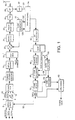
- FIG. 1 shows a block diagram of transmit and receive circuitry at a mobile station (MS) in a CDMA system
- Figure 2 shows a block diagram illustrating a context in which the present application may be used. That is, the CDMA mobile communication system allows a plurality of mobile stations MS 1, MS 2, MS 3 to communicate with a base transceiver station BTS 1 in the common cell via respective channels CH 1, CH 2, CH 3. Mobile station MS 3 is able to communicate at the same time as it communicates with the first base transceiver station BTS 1 with a second base transceiver station BTS 2. This allows soft hand off to be achieved. Soft hand off occurs, for example when a mobile station is close to the edge of two or more adjacent cells.
- Soft hand off occurs, for example when a mobile station is close to the edge of two or more adjacent cells.
- the mobile station MS 3 communicates with the second base transceiver station BTS 2 using the channel CH 4.
- the information transmitted on the channels CH 3 is the same as the information transmitted on the channel CH 4 and the same spreading code is used for both channels.
- the third mobile station MS 3 provides a single transmission which provides both the third and fourth channels CH 3 and CH 4.
- the three channels which are used to communicate with the first base transceiver station BTS 1 are distinguished from one another by the use of spreading codes in a manner which is known.
- Data to be transmitted which may be speech data, video data or other data is supplied to the MS interface 2. It is encoded into a form suitable for transmission.
- the encoded user data is supplied to a frame multiplexer 4 via line 6 together with a rate information sequence RI via line 8 which identifies the bit rate, a check sequence (CRC) for each frame of data via line 10 and an error correction tail bit defining the end of each user data sequence via line 12.
- the frame multiplexer 4 organises the data for transmission into a frame sequence.
- the frame sequence is supplied to a convolutional encoder 14 and a bit interleaver 16.
- These circuits carry out convolutional encoding and bit interleaving in a manner which is known in the art and which will not be described further herein.
- the purposes of the convolutional encoding is to protect the user data from errors in a radio channel so that a (Viterbi) decoder can recover the coded data even if some bits are corrupted.
- Bit interleaving spreads burst errors which typically occur in mobile radio channels more evenly in time to allow the decoder to more efficiently correct the errors from the coded data.
- pilot symbols are introduced into the time slots with the encoded data to generate a slot sequence.
- the pilot symbols (PS) are introduced at the beginning and end of each time slot in a coherent system. These symbols are easily recognisable and so the beginning and end of each time slot can be identified for synchronisation purposes. In a non-coherent system, these pilot symbols are not necessary.
- the slot sequence is supplied to a spreader 20 which receives a spreading code from the code generator 22.
- the spreading code is generated in accordance with known CDMA techniques and will not be described further herein.
- the spreading code is unique for each mobile station transmitting to a single base station so that the transmission from individual mobile stations can be distinguished at the base station.
- the codes are designed to be as far as possible orthogonal between different mobile stations.
- M parallel code channels are employed, M data symbols are spread using different codes.
- the spread signal is supplied to a modulator 24 which modulates the signal ready for transmission, for example according to QPSK modulation. In some systems, modulation is carried out prior to spreading.
- the spread, modulated signal is supplied to a pulse shaping filter 25 which shapes the digital signal into a form which is easier for a digital to analogue (D/A) converter 26 to deal with.
- the D/A converter 26 is connected to output of the pulse shaping filter 25.
- the analogue signal is input to an RF unit 28 which supplies the signal ready for transmission via an antenna 30.
- the RF unit 28 converts the signal from either an intermediate frequency or a base band frequency to the radio frequency.
- the RF unit 28 may thus comprise a mixer.
- Signals incoming at the antenna 30 are received by the RF unit 28 and supplied to an analogue to digital (A/D) converter 32 which converts the received analogue signal to a digital signal.
- the RF unit 28 may convert the received signals at the radio frequency to an intermediate or baseband frequency. It will readily be understood that a signal may arrive at the mobile station having experienced multipaths with differing propagation delays.
- the A/D converter 32 supplies the digital signal to a RAKE receiver 34 which will be described in more detail hereinafter.
- the RAKE receiver 34 also receives an input from the code generator 22.
- the output of the RAKE receiver 34 is input to a bit detector 42.
- the bit detector 42 makes a soft or hard decision on the received symbols as to the transmitted bits.
- the detected bit sequence from the bit detector 42 is supplied to a slot demultiplexer 44 which demultiplexes the slot structure and provides an estimate of the transmission rate calculated by the RAKE receiver.
- the demultiplexed slot structure is then supplied to a deinterleaving unit 46 which effectively undoes the action of the interleaver 16.
- the deinterleaved signal is supplied to a Viterbi decoding unit 48 with the rate information.
- the decoded signal determined by the Viterbi decoding unit 48 is supplied to a frame demultiplexer 50 from which the tail bit, user data, CRC sequence and RI sequence are recovered.
- the user data is supplied to the transmission interface 2 along line 52.
- the rate information sequence RI is supplied to a rate detection unit 54 along line 56.
- the rate detection unit compares the decoded rate information with the estimated rate and if there is a mismatch, a signal is supplied to the Viterbi decoding unit 48 along line 58 to allow the Viterbi decoding unit to make a different rate decision for decoding.
- An additional check on the rate information, and also on the validity of the data itself, is accomplished by supplying the user data to a CRC encoder 60 which generates a CRC sequence from the received user data.
- the CRC sequence is checked against the CRC sequence derived from the incoming data in a CRC check unit 62. If the check is valid, then it is assumed that the rate information and the data are good. If the CRC check fails, the estimated rate supplied to the Viterbi decoding unit can be used to make a next guess at the right transmission rate for decoding.
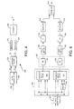
- the RAKE receiver 34 will now be described in more detail with reference to Figure 3.
- the RAKE receiver 34 comprises a plurality of RAKE fingers 100 1-n .
- the number of RAKE fingers vary in dependence on the requirements of the mobile phone. In one embodiment six fingers are provided.
- Each RAKE finger 100 comprises a correlator 101, a channel estimator 104, a coherence time estimator 106, an adjustable filter 108 and a phase rotation unit 110.
- the input to each RAKE finger 100 is provided to the correlator 101.
- the correlator 101 provides an output to the phase rotation unit 110 and to the channel estimator 104.
- the output of the channel estimator 104 is provided to the adjustable filter 108 and to the coherence time estimator 106.
- the output of the coherence time estimator 106 is connected to another input of the adjustable filter 108.
- the adjustable filter output is connected to another input of the phase rotation unit 110.
- the output of each phase rotation unit 110 is connected to the input of a delay equalizer 150.
- the output of each delay equalizer 150 is input to a combiner 38.
- the combiner 38 also provides a demodulation function.
- the output of the combiner 38 may be input to a separate demodulator.
- the output of the combiner 38 is connected to the input of the bit detector 42 as shown in Figure 1.
- the RAKE receiver 34 also comprises a sounding block 114 (sometimes referred to as a searcher) which searches through the received signals to ascertain when each multipath propagation reaches the mobile station, or if there is base station diversity to ascertain when the respective signals from the base stations reach the mobile station.
- Base station diversity occurs, for example, during soft handoff where more than one base station is sending the same signal to the same mobile station.
- Sounding blocks are well known in the art and accordingly the specific structure of the sounding block will not be described. Any suitable method can be used to perform this sounding such as fast Fourier transforms etc.
- the sounding block 114 effectively correlates the received signal with the respective code but with a variety of delays.
- the results of a typical sounding correlation are shown in Figure 5.
- the first correlation is obtained when the code is delayed with respect to the received signal by relative delay ⁇ 1.
- the next two correlations, which are decreasing in size are obtained when the relative delays are ⁇ 2 and ⁇ 3 respectively.
- Another large correlation is obtained when the relative delay is ⁇ 4.
- the first correlation peak corresponds to the strongest multipath signal received from a given base transceiver station with the second and third peaks corresponding to two multipath propagations of the same signal from the same base station.
- the fourth peak corresponds to the strongest multipath signal received from a second base transceiver station which is probably further from the mobile station than the first base transceiver station.
- the fifth and sixth peaks correspond to multipath propagations of the signal received from the second base transceiver station. Typically, these multipath propagations from any given base station will be grouped together and can easily be distinguished from a second group of signals which come from a second base transceiver station.
- the sounding block 114 determines the different phases (or delays) for each multipath propagation and these delays are sent to the respective fingers of the RAKE receiver 34 allocated to deal with a particular multipath propagation.
- the sounding block 114 has ascertained the delays at which the correlation peaks are obtained, these delays are provided to different fingers. For example, if there are six fingers, the first finger will correlate the received signal with the code having delay ⁇ 1, the second signal will correlate the signal with the code having a delay ⁇ 2, the third finger will correlate the signal with the code having a delay ⁇ 3 and so on. If there are more correlation peaks than fingers, the sounding block may be arranged to select the strongest signals for allocation to the respective fingers. The assigned delay for each finger 101 is output to the correlator of the respective finger via lines 124 1-n .
- the sounding block 114 also provides outputs 149 to respective delay equalizers 150 of each RAKE finger 100.
- the outputs 149 provided by the sounding block 114 to the delay equalizers 150 ensure that the outputs of the respective fingers 100 are synchronised and can be combined meaningfully by the combiner 38. For example, if there were only three fingers which are allocated to process the peaks which occur at delay time ⁇ 1, ⁇ 2 and ⁇ 3, it is arranged so that the output from each finger occurs at the same time so that the signals can be superimposed by the combiner 138 with the peaks occurring at delays ⁇ 1, ⁇ 2 and ⁇ 3 coinciding. Thus the peak with delay ⁇ 1 will be delayed by a time period of ⁇ 3- ⁇ 1 with respect to the peak with delay ⁇ 3.
- the second peak will be delayed by a time period of ⁇ 3- ⁇ 2 with respect to the peak with delay ⁇ 3.
- the peaks corresponding to delays ⁇ 1, ⁇ 2 and ⁇ 3 will be output by the respective fingers to the combiner 38 at the same time
- the code generator 22 provides an input to the sounding block 114 via line 120 as well as to each correlator 101 via line 122 of the respective fingers 100.
- Each correlator 101 of each finger 100 receives the output from the A/D converter 32 via line 33, the associated code from the code generator 22 via line 122 and the assigned delay from the sounding block 144 via line 124. Each correlator 101 correlates the received signal with the code from the code generator 22, the code having been delayed by the amount determined by the sounding block 114 and assigned to the particular finger 100. The correlators 101 thus despread the received signal.
- the output of the correlator 101 of each finger is input to the channel estimator 104.
- the signal receiving unit needs to establish from the signal which it has received some information about the communication path along which the signal has travelled. This is referred to as "channel estimation” and is carried out in a channel estimator 104 unit which generates a channel impulse response.
- channel estimation Various techniques are known for channel estimation. The channel impulse response is required in order to properly decode and demodulate the incoming data.
- the channel estimator 104 therefore estimates the channel impulse response for the received and correlated signal.
- the channel estimation may be based on pilot symbols in the received signal.
- the pilot symbols can be regarded as reference signals.
- the channel estimator 104 will correlate the received pilot symbols with reference pilot symbols which are available in the receiver. The correlation effectively allows a comparison to be made between the pilot symbols which should be received and the pilot symbols which are actually received.
- the channel estimate determined by the channel estimator 104 is also used to control the adjustable filter 108 as well as by the coherence time estimator 106 to estimate the coherence time of the channel.
- the coherence time of a channel is the interval over which a transmitted symbol will be relatively undisturbed by fluctuations in the channel. Fluctuations in the channel may be caused by movement of the mobile station which might be in a moving vehicle or by changes in the radio environment.
- the coherence time estimator 106 is arranged to estimate the coherence time of the channel and the components of the coherent time estimator 106 will be described with reference to Figure 4.
- the coherence time is based on the estimated speed of the mobile station. Generally, the faster that the mobile station moves, the shorter the coherence time.
- the speed of the mobile station can be estimated in a number of different ways. A preferred method of estimating the speed of the mobile station is described in relation to the coherence time estimator 106 shown in Figure 4.
- the coherence time estimator 106 comprises an autocorrelation unit 120, the input of which is connected to the output of the channel estimator 104.
- the output of the autocorrelation unit 120 provides two outputs which are input to a low pass filter unit 122.
- the low pass filter unit 122 has two outputs, each of which is connected to a respective absolute block 124 and 126.
- the output.of each of the absolute blocks 124 and 126 is input to a division unit 128.
- the output of the division unit 128 is connected to one input of the adjustable filter 108.
- the channel impulse response calculated by the channel estimator 104 is input to the autocorrelation unit 120.
- An autocorrelation function is then performed on the channel impulse response.
- the input channel impulse response is therefore correlated with itself.
- the autocorrelation of the channel impulse response is taken with delays of 0 and ⁇ .
- the channel impulse response is correlated with itself in one case with no delay between the two versions of the channel impulse response and in the other case with one version of the channel impulse response being delayed with respect to the other version of the channel impulse response by time ⁇ .
- the results of these two autocorrelations are output on the respective outputs of the autocorrelation unit 120 to the low pass filter unit 122.
- the low pass filter unit 122 averages the autocorrelations performed by the autocorrelation unit 122 to provide two average values.
- the first average value represents the average of the autocorrelations with no delay whilst the other value represents the average of the autocorrelations with the delay ⁇ .
- the autocorrelation values obtained when there is no delay represent the maximum autocorrelation values.
- R c ( ⁇ ) E[c 0 (t)c 0 *(t+ ⁇ )]
- the averaging of the respective autocorrelation values will reduce the effects of noise.
- the two average values are output by the respective outputs of the low pass filter unit 122 and are input to respective ones of the absolute blocks 124.
- the absolute blocks 124 calculate the absolute value (that is magnitude) of each of the averaged values.
- the calculated absolute values are output by the respective absolute blocks 124 to the division block 128.
- the division block 128 compares the two average values in order to provide a correlation coefficient p. In particular the division block 128 performs the following calculation.
- P
- Figure 6 shows one way how the schematic arrangement of Figure 4 can be implemented in practice.
- the output of the channel estimator 104 is input to a first decimator 152.
- the output of the channel estimator 104 is represented as two separate signals, one of which corresponds to the I component and one of which corresponds to the Q component.
- the decimator reduces the size of the input signals by discarding m out of every n bits.
- m and n can have any suitable values and in embodiment of the invention all of the non-pilot symbols in a time slot are discarded. It is possible, in one modification to this embodiment that all the non-pilot symbols and some of the pilot symbols be discarded for each time slot.
- the first decimator 152 provides two outputs, again corresponding to the I and Q components of the signal. These two outputs are input to the autocorrelation unit 120 which includes a first complex multiplier 130 which provides the autocorrelation values with no delay and a second complex multiplier which provides the autocorrelation with delay ⁇ .
- the first complex multiplier 130 receives the I component of the signal at two separate inputs and the Q component of the signal at two separate inputs.
- the second complex multiplier 132 has a first input for the I component of the signal and a second input for the Q component of the signal.
- the second complex multiplier also has two inputs connected to two outputs of a delay unit 134.
- the delay unit 134 receives at one input the I component and at a second input the Q component of the signal from the respective outputs of the first decimator 152.
- the delay unit 134 delays these signals by a time ⁇ before outputting the I and Q components to the second complex multiplier 132.
- the autocorrelation functions are thus carried out by the first and second complex multipliers 130 and 132.
- the output of the first complex multiplier 130 is output to a first infinite impulse response (IIR) filter 136.
- the output of the second complex multiplier 132 is output to a second IIR filter 138.
- the outputs of the first and second IIR filters 136 and 138 are output to respective second and third decimators 140 and 142.
- the second and third decimators 140 and 142 provide the same function as the first decimator 152 although the values of m and n may be different. It should be noted that the values of m and n will be the same for the second and third decimators 140 and 142.
- the output of the second and third decimators 140 and 142 are input to the third and fourth IIR filters 145 and 146.
- the four IIR filters 136, 138, 145 and 146 and the second and third decimators 140 and 142 are arranged to average the results of the autocorrelations carried out by the autocorrelation unit 120.
- the third and fourth IIR filters 145 and 146 provide the actual averaging function.
- the second and third decimators 140 and 142 reduces the number of samples which are passed to the third and fourth IIR filters 145 and 146 and thus the complexity of the third and fourth IIR filters can be reduced.
- the output of the third and fourth IIR filters are input to respective absolute blocks 124, as in Figure 4.
- the outputs of the absolute blocks 124 are input to division unit 128 which performs the same function as that of Figure 4.
- the most appropriate values of m and n for the first to third decimators 152, 140 and 142 can be determined experimentally.
- the channel estimates provided by the channel estimator 104 are affected by noise.
- the adjustable filter 108 is provided to reduce the effects of noise. By filtering the channel estimates before they are used to correct the phase of the signal in the phase rotation block 110, the results of the phase rotation block 110 will be more accurate. In other words the adjustable filter improves the signal to noise ratio of the channel estimates.
- the adjustable filter 108 is thus arranged so that its operational characteristics is altered in response to the coherence time estimated by the coherence time estimator 106 for the particular propagation path which is being dealt with by that RAKE finger 100. More particularly, the operation of the adjustable filter 108 is altered to take into account the current value of the correlation coefficient. The adjustable filter 108 then filters the channel estimates calculated by the channel estimator 104. It should be appreciated that each RAKE finger 100 considers a single propagation path at a time.
- the adjustable filter 108 is a therefore a programmable filter which is programmed in accordance with the estimated coherence time.
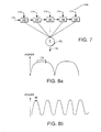
- the filter 108 comprises a number of delay blocks 160-168.
- the number of delay blocks can be varied as required. However, for illustrative purposes only, the filter 108 of Figure 7 is provided with five delay blocks 160-168.
- the input 170 to the filter 108 is connected to the first delay block 160 which has two outputs, one of which is connected to the second delay block 162 and the other of which is connected to a summing unit 172.
- the second delay block 16 has two outputs, one of which is connected to the third delay block 164 and the other of which is connected to the summer 172.
- the third and fourth delay blocks 164 and 166 each have two similar outputs.
- the fifth delay block 168 has a single output which is connected to the summer 172.
- Each delay block has a second input 174 which provides the allocated coefficient for the particular delay block.
- This general structure is used by FIR (finite impulse response) filters, IIR filters and Wiener filters which can all be used in embodiments of the present invention. The different functions achieved by these filters is achieved by the coefficients applied to the delay blocks 160-168.
- the output of the filter 108 is supplied by the output 176 of the summer 172 which sums the outputs of each of the delay blocks 160-168.
- the adjustable filter 108 which provides a smoothing function may be as mentioned hereinbefore a flat FIR filter, an IIR filter, a Wiener filter or any other suitable type of filter.
- the adjustable filter can therefore also be referred to as a smoother or a smoothing filter.
- Wiener filters the coefficients used are adapted to the particular Doppler spectrum.
- the coefficient p may be used to alter these coefficients and/or the number of taps used.
- a flat FIR filter is an average where every tap coefficient has the same value. For example in a 20 tap filter, each filter coefficient will have the same value which, for example may be 0.05.
- the number of taps used will be varied in accordance the coherence time estimate provided by the coherence time estimator 106.
- a Wiener filter attempts to obtain a optimal channel estimate by passing the channel estimates through a linear phase filter which minimizes the mean square error of the signal.
- a linear phase filter which minimizes the mean square error of the signal.
- Such a function can be difficult to implement in practice and a adjustable linear phase, low pass filter with a cut off frequency grater than or equal to the maximum possible Doppler frequency may be used.
- FIGS 8a and 8b respectively shows a channel with a long coherence time and a short coherence time.
- the longer coherence time (fading rate) is obtained with slower moving mobile stations whilst the shorter coherence time is obtained with faster moving stations.
- the y axis of figures 8a and 8b represents power. Referring first to Figure 8a, the time period over which channel estimates should be made is indicated by region 178 where the values are relatively constant. Therefore the filter 108 will use a relatively large number of values in order to determine the filter output 176. Thus all the delay blocks may be used and the tap coefficients for each delay block may be quite similar.
- region 180 the time period over which channel estimates should be made is indicated by region 180, again where the values are relatively constant. However region 180 is much shorter than region 178. Therefore fewer delay blocks will be used. For example some of the coefficients for the delay blocks will be 0. In both examples, the non zero coefficients will be selected in accordance with the length of regions 176 and 180 which represent the coherence time of the respective channel. In both examples, if the size of the regions 176 and 180 were to be increased to be longer than the channel coherence time, the channel estimates would be inaccurate and would provide inaccurate results as the channel estimates would no longer correspond to the channel impulse response.
- the RAKE receiver effectively collects signal energy from different delay paths of the channel which are combined by the combiner 38. Each individual path is assumed to introduce an independent fading characteristic. As discussed hereinbefore n different delay or propagation paths may be present. It is possible to perform maximum ratio combining of the different delay paths. Maximum ratio combining effectively weights the signals before the signals are combined so that the strongest signals are given most weight. This accuracy of this calculation will depend on the accuracy of channel estimates which are calculated by the channel estimators 104. The adjustable filter 108 will therefore smooth the channel estimates obtained by the channel estimator 104.
- the channel estimates provided by the channel estimator 104 are output to the coherence time estimator 106 which uses the estimates to estimate the coherence time and also to the adjustable filter 108 which then filters the taps. As discussed hereinbefore, the characteristics of the adjustable filter 108 will depend on the coefficient calculated by the channel coherence time estimator 106.
- the combiner 38 coherently combines the signal provided by each of the RAKE fingers 100. Coherent combination is possible due the presence of the phase rotation unit 110 in each finger 100. In particular, in coherent combination, the phase of the signal provided by each finger is the same. It should be appreciated that in alternative embodiments of the present invention non-coherent combining can take place.
- the phase rotation unit 100 causes the correlated output provided by the correlator 101 to be multiplied by the filtered channel estimates output by the adjustable filter 108.
- the function of the delay equalizer 150 which is arranged between the phase rotation unit and the combiner 38 has been described hereinbefore.
- phase rotation unit 100 ensures that the signals which are to be combined have the same phase whilst the delay equalisers 150 ensure that the signals to be combined are delayed with respect to each so that corresponding parts of the signals are output from the delay equalizers 150 at the same time.
- the combiner 38 can use any suitable algorithm for combining the signals. For example, different weighting factors can be used with the signals from different fingers. In one embodiment of the present invention, the estimate provided by the combiner 38 for the transmitted data signal is as follows:
- Each finger 100 provides the result of the signal for a given propagation path x the complex conjugate of the channel tap complex estimate. The results from each finger 100 are then summed.
- the system shown in Figure 4 or Figure 6 for estimating the coherence time of a channel can be implemented in a digital signal processor which also provides other processing functions for the receiver. Alternatively, separate components or a separate processor may be provided to estimate the coherence time for each finger.
- a linear interpolator may be added after the adjustable filter to interpolate the values of the estimates between two consecutive time slots.
- the estimate of the coherence time of the channel is based on the estimate speed of the mobile station.
- any other suitable technique can alternatively be used to measure the coherence time of the channel.
- the correlating function of the sounding block may be achieved with matched filters. It is also possible that the correlator in each finger may be replaced by matched filters.
- the channel estimate may be based on data symbols instead of pilot symbols.
- the estimates may be based on pilot and data symbols.
- the filter function provided by the adjustable filter can be implemented using any other suitable filter construction instead of the filter construction shown in Figure 7.
- embodiments of the present invention have been described in relation to mobile stations, embodiments of the present can also be incorporated in base transceiver stations.
- the base transceiver stations may be mobile or stationary.
- embodiments of the present invention may be incorporated in fixed devices which may communicate with base stations or the like.
- advantages may still be achieved in that the radio environment itself may be changing due to the movement of for example traffic or the like.
- Embodiments of the present invention are particularly applicable to code division multiple access systems and wideband code division multiple access systems.
- embodiments of the present invention can be used with virtually any other access system, such as other spread spectrum systems, time division multiple access systems, frequency division multiple access systems and hybrids of these access systems.
Landscapes
- Engineering & Computer Science (AREA)
- Computer Networks & Wireless Communication (AREA)
- Signal Processing (AREA)
- Mobile Radio Communication Systems (AREA)
- Radio Relay Systems (AREA)
- Time-Division Multiplex Systems (AREA)
- Structure Of Receivers (AREA)
- Transplanting Machines (AREA)
Claims (19)
- Récepteur destiné à être utilisé dans un système de communications sans fil, ledit récepteur comprenant une pluralité de moyens de réception (1001 ... 100n), lesdits plusieurs moyens de réception étant chacun agencé pour recevoir des signaux provenant d'un trajet de propagation différent, chacun desdits moyens de réception comprenant des moyens (106) destinés à estimer le temps de cohérence pour le trajet de propagation utilisé par les signaux reçus par les moyens de réception respectifs et des moyens de filtrage (108), où le fonctionnement de chacun des moyens de filtrage est modifié en fonction de l'estimation du temps de cohérence pour ledit trajet de propagation fournie par les moyens d'estimation respectifs.
- Récepteur selon la revendication 1, dans lequel ledit récepteur est un récepteur de type RAKE et lesdits moyens de réception comprennent des modules (dents).
- Récepteur selon l'une quelconque des revendications précédentes, dans lequel les coefficients de prises pour lesdits moyens de filtre sont modifiables en fonction de l'estimation du temps de cohérence.
- Récepteur selon l'une quelconque des revendications précédentes, dans lequel le nombre des prises utilisées dans chacun desdits moyens de filtrage est modifiable en fonction de l'estimation du temps de cohérence respective.
- Récepteur selon l'une quelconque des revendications précédentes, dans lequel ledit moyen de filtrage a pour caractéristique que l'erreur quadratique moyenne finale est minimisée.
- Récepteur selon la revendication 5, dans lequel ledit moyen de filtrage de chaque moyen de réception comprend un filtre de Wiener.
- Récepteur selon l'une quelconque des revendications précédentes, dans lequel ledit moyen de filtrage de chaque moyen de réception comprend un filtre à réponse impulsionnelle finie.
- Récepteur selon l'une quelconque des revendications précédentes, dans lequel ledit moyen de filtrage de chaque moyen de réception comprend un filtre à réponse impulsionnelle infinie.
- Récepteur selon l'une quelconque des revendications précédentes, dans lequel le récepteur est incorporé dans une station mobile.
- Récepteur selon l'une quelconque des revendications précédentes, dans lequel ledit moyen d'estimation estime le temps de cohérence du trajet de propagation associé au moyen de réception respectif sur la base d'un paramètre indicatif du déplacement de la station mobile.
- Récepteur selon la revendication 10, dans lequel ledit paramètre indicatif du déplacement de la station mobile est défini par un rapport d'une première autocorrélation d'une réponse impulsionnelle de canal, sans délai, pour le trajet de propagation associé à un récepteur donné et d'une seconde autocorrélation de ladite réponse impulsionnelle de canal avec un délai donné.
- Récepteur selon la revendication 11, dans lequel lesdites première et seconde autocorrélations sont des valeurs moyennes.
- Récepteur selon l'une quelconque des revendications précédentes, dans lequel la sortie dudit moyen de filtrage est utilisée pour commander une modification de phase appliquée aux signaux reçus.
- Récepteur selon l'une quelconque des revendications précédentes, dans lequel ledit moyen d'estimation est agencé pour recevoir une pluralité d'estimations de réponses impulsionnelles de canal pour ledit signal reçu, lesdites estimations de réponses impulsionnelles de canal étant utilisées par ledit moyen d'estimation pour estimer le temps de cohérence de canal.
- Récepteur selon l'une quelconque des revendications précédentes, dans lequel ledit récepteur est incorporé dans une station d'émetteur-récepteur de base.
- Récepteur selon l'une quelconque des revendications précédentes, dans lequel ledit récepteur est agencé pour recevoir des signaux dans le format à accès multiples par répartition de code.
- Récepteur destiné à être utilisé dans un système de communications sans fil, ledit récepteur comprenant une pluralité de moyens de réception (1001 ... 100n), lesdits plusieurs moyens de réception étant chacun agencé pour recevoir des signaux provenant d'un trajet de propagation différent, chacun desdits moyens de réception comprenant des moyens de filtrage adaptatifs (108) destinés à filtrer lesdits signaux reçus, où le fonctionnement de chaque dit moyen de filtrage adaptatif est modifié en fonction d'une caractéristique des signaux provenant du trajet de propagation reçu par les moyens de réception respectifs.
- Récepteur selon la revendication 17, dans lequel lesdits signaux reçus sont traités avant de passer par les moyens de filtrage adaptatif.
- Récepteur selon la revendication 17 ou 18, dans lequel ladite caractéristique est le temps de cohérence pour le trajet de propagation utilisé par lesdits signaux reçus par le récepteur respectif.
Applications Claiming Priority (3)
| Application Number | Priority Date | Filing Date | Title |
|---|---|---|---|
| GB9818378 | 1998-08-21 | ||
| GBGB9818378.3A GB9818378D0 (en) | 1998-08-21 | 1998-08-21 | Receiver |
| PCT/EP1999/005827 WO2000011798A1 (fr) | 1998-08-21 | 1999-08-10 | Recepteur adaptatif a propagation sur plusieurs voies pour systeme amcr de telecommunications |
Publications (2)
| Publication Number | Publication Date |
|---|---|
| EP1105977A1 EP1105977A1 (fr) | 2001-06-13 |
| EP1105977B1 true EP1105977B1 (fr) | 2004-10-13 |
Family
ID=10837705
Family Applications (1)
| Application Number | Title | Priority Date | Filing Date |
|---|---|---|---|
| EP99941569A Expired - Lifetime EP1105977B1 (fr) | 1998-08-21 | 1999-08-10 | Recepteur adaptatif a propagation sur plusieurs voies pour systeme amcr de telecommunications |
Country Status (10)
| Country | Link |
|---|---|
| US (1) | US6680967B1 (fr) |
| EP (1) | EP1105977B1 (fr) |
| JP (1) | JP2002523961A (fr) |
| KR (1) | KR20010072840A (fr) |
| CN (1) | CN1117434C (fr) |
| AT (1) | ATE279815T1 (fr) |
| AU (1) | AU5513599A (fr) |
| DE (1) | DE69921155T2 (fr) |
| GB (1) | GB9818378D0 (fr) |
| WO (1) | WO2000011798A1 (fr) |
Families Citing this family (44)
| Publication number | Priority date | Publication date | Assignee | Title |
|---|---|---|---|---|
| FI19991871A (fi) * | 1999-09-02 | 2001-03-02 | Nokia Networks Oy | Menetelmä signaalikomponenttien käsittelemiseksi kommunikaatiojärjestelmässä ja vastanotin |
| DE19961594B4 (de) * | 1999-12-21 | 2013-08-14 | Ipcom Gmbh & Co. Kg | Verfahren für die Übertragung von Datensignalen zwischen einer Sendestation und mehreren Empfangsstationen, Sendestation und Empfangsstation |
| JP2001257627A (ja) * | 2000-03-13 | 2001-09-21 | Kawasaki Steel Corp | 無線受信機 |
| FI118877B (fi) | 2000-06-19 | 2008-04-15 | Valtion Teknillinen | Liiketilan estimointi |
| US7065130B1 (en) * | 2000-10-02 | 2006-06-20 | Telefonaktiebolaget Lm Ericsson (Publ) | Searching for signals in a communications system |
| CN1140075C (zh) * | 2000-12-18 | 2004-02-25 | 信息产业部电信传输研究所 | 基于多径能量窗的码分多址系统初始同步与小区搜索装置 |
| US6922452B2 (en) * | 2001-03-27 | 2005-07-26 | Telefonaktiebolaget L M Ericsson (Publ) | Method and apparatus for estimating Doppler spread |
| US20020176485A1 (en) * | 2001-04-03 | 2002-11-28 | Hudson John E. | Multi-cast communication system and method of estimating channel impulse responses therein |
| KR100393192B1 (ko) * | 2001-07-11 | 2003-07-31 | 삼성전자주식회사 | 시변 채널에 적합한 신호 수신 장치 및 방법 |
| EP1296156B1 (fr) * | 2001-09-25 | 2009-01-28 | STMicroelectronics N.V. | Procédé et dispositif d'estimation de la vitesse d'un terminal mobile, en particulier un téléphone mobile cellulaire capable de fonctionner selon la norme UMTS |
| GB0126130D0 (en) * | 2001-10-31 | 2002-01-02 | Nokia Corp | Frequency error estimation |
| US7164649B2 (en) * | 2001-11-02 | 2007-01-16 | Qualcomm, Incorporated | Adaptive rate control for OFDM communication system |
| US7209433B2 (en) * | 2002-01-07 | 2007-04-24 | Hitachi, Ltd. | Channel estimation and compensation techniques for use in frequency division multiplexed systems |
| US7263349B2 (en) | 2002-03-12 | 2007-08-28 | Qualcomm Incorporated | Velocity responsive time tracking |
| US7203527B2 (en) * | 2002-05-06 | 2007-04-10 | Via Telecom, Inc. | Method and apparatus for reducing power of a CDMA mobile station by controlled transition from control hold to active state |
| JP3961907B2 (ja) * | 2002-08-23 | 2007-08-22 | 富士通株式会社 | フェージング周波数推定装置 |
| TW579636B (en) * | 2002-10-25 | 2004-03-11 | Benq Corp | Method and system for estimating movement speed of mobile phone |
| US7286481B2 (en) * | 2002-12-17 | 2007-10-23 | Intel Corporation | Wireless network adapted to transmit channel side information and method thereof |
| US20040125865A1 (en) * | 2002-12-30 | 2004-07-01 | Frank Colin D. | Maximum signal-to-interference-and-noise spread spectrum rake receiver and method |
| DE60335496D1 (de) * | 2003-01-30 | 2011-02-03 | Fujitsu Ltd | Fading-frequenzschätzvorrichtung |
| US7301990B2 (en) * | 2003-02-21 | 2007-11-27 | Qualcomm Incorporated | Equalization of multiple signals received for soft handoff in wireless communication systems |
| DE10322943B4 (de) * | 2003-05-21 | 2005-10-06 | Infineon Technologies Ag | Hardware-Vorrichtung zur Aufbereitung von Pilotsymbolen für eine Kanalschätzung mittels adaptiver Tiefpassfilterung |
| US7869488B2 (en) * | 2003-08-28 | 2011-01-11 | Qualcomm Incorporated | Method and apparatus for removing code aliases when using short synchronization codes |
| US20050047491A1 (en) * | 2003-08-28 | 2005-03-03 | Haitao Zhang | Method and apparatus for improving channel estimate based on short synchronization code |
| EP2603041A1 (fr) * | 2003-09-04 | 2013-06-12 | Fujitsu Limited | Système de communication et procédé de communication de transfert |
| KR100712323B1 (ko) * | 2003-10-02 | 2007-05-02 | 삼성전자주식회사 | 패킷 통신 시스템에서 빠른 전송율 변화를 지원하는 역방향 전송율 스케쥴링 방법 및 장치 |
| US7903617B2 (en) * | 2003-12-03 | 2011-03-08 | Ruey-Wen Liu | Method and system for multiuser wireless communications using anti-interference to increase transmission data rate |
| US20050193315A1 (en) * | 2004-02-18 | 2005-09-01 | Massimo Bertinelli | Method and apparatus for performing a TFCI reliability check in E-DCH |
| JP4744965B2 (ja) | 2004-08-09 | 2011-08-10 | パナソニック株式会社 | 無線通信装置 |
| US8503328B2 (en) * | 2004-09-01 | 2013-08-06 | Qualcomm Incorporated | Methods and apparatus for transmission of configuration information in a wireless communication network |
| US7372895B2 (en) * | 2004-12-08 | 2008-05-13 | Telefonaktiebolaget Lm Ericsson (Publ) | Method of and system for delay estimation with minimized finger allocation |
| US7610025B2 (en) * | 2005-03-29 | 2009-10-27 | Qualcomm Incorporated | Antenna array pattern distortion mitigation |
| US7917798B2 (en) | 2005-10-04 | 2011-03-29 | Hypres, Inc. | Superconducting digital phase rotator |
| GB0601952D0 (en) * | 2006-01-31 | 2006-03-15 | M M I Res Ltd | Methods of maintaining connection with, and determining the direction of, a mobile device |
| WO2008107848A1 (fr) * | 2007-03-06 | 2008-09-12 | Nxp B.V. | Perfectionnements à ou reliés à des récepteurs et à des systèmes de communication à accès multiple par répartition en code |
| CN101682297B (zh) * | 2007-06-04 | 2012-06-27 | Nxp股份有限公司 | 包含频带选择的数字信号处理电路和方法 |
| FR2943193B1 (fr) * | 2009-03-13 | 2011-04-01 | St Ericsson Sa | Procede d'affectation et de liberation d'un correlateur dans un recepteur de type rake et recepteur pour la mise en oeuvre du procede |
| FR2943192B1 (fr) * | 2009-03-13 | 2011-06-03 | St Wireless Sa | Procede d'affectation d'un doigt (finger) pour un recepteur de type rateau (rake) en mode de veille,et dispositif pour la mise en oeuvre du procede |
| US8559887B2 (en) * | 2009-07-09 | 2013-10-15 | Cisco Technology, Inc. | Coherence time estimation and mobility detection for wireless channel |
| CN101707493B (zh) * | 2009-08-26 | 2012-09-26 | 南京邮电大学 | 多径信号载波相干解调瑞克接收机 |
| US8606254B2 (en) | 2009-10-30 | 2013-12-10 | Blackberry Limited | Method and system for receiver adaptation based on knowledge of wireless propagation environments |
| US8737457B2 (en) | 2012-09-28 | 2014-05-27 | Telefonaktiebolaget L M Ericsson (Publ) | Adaptive smoothing of channel estimates |
| US8737550B1 (en) | 2012-12-04 | 2014-05-27 | Telefonaktiebolaget L M Ericsson (Publ) | Estimating optimal linear regression filter length for channel estimation |
| US10715288B2 (en) * | 2016-05-10 | 2020-07-14 | Apple Inc. | Wireless local area network sounding protocol |
Family Cites Families (14)
| Publication number | Priority date | Publication date | Assignee | Title |
|---|---|---|---|---|
| DE69129768T2 (de) | 1990-03-30 | 1999-02-25 | Nec Corp., Tokio/Tokyo | Störungsunempfindlicher Raumdiversityempfänger |
| JP3100447B2 (ja) * | 1992-01-10 | 2000-10-16 | 三菱電機株式会社 | 適応等化器および受信機 |
| GB9315845D0 (en) * | 1993-07-30 | 1993-09-15 | Roke Manor Research | Apparatus for use in equipment providing a digital radio link between a fixed and a mobile radio unit |
| US5544156A (en) * | 1994-04-29 | 1996-08-06 | Telefonaktiebolaget Lm Ericsson | Direct sequence CDMA coherent uplink detector |
| JP3118548B2 (ja) * | 1994-06-22 | 2000-12-18 | 株式会社エヌ・ティ・ティ・ドコモ | ディジタル通信受信機用同期検波装置および同期方法 |
| FI943249A (fi) | 1994-07-07 | 1996-01-08 | Nokia Mobile Phones Ltd | Menetelmä vastaanottimen ohjaamiseksi ja vastaanotin |
| FI110731B (fi) | 1994-09-12 | 2003-03-14 | Nokia Corp | Menetelmä kanavan estimoimiseksi ja vastaanotin |
| US5697084A (en) * | 1994-09-16 | 1997-12-09 | Bose Corporation | Reducing multipath fading using adaptive filtering |
| US5619524A (en) * | 1994-10-04 | 1997-04-08 | Motorola, Inc. | Method and apparatus for coherent communication reception in a spread-spectrum communication system |
| US6263307B1 (en) * | 1995-04-19 | 2001-07-17 | Texas Instruments Incorporated | Adaptive weiner filtering using line spectral frequencies |
| US5584295A (en) * | 1995-09-01 | 1996-12-17 | Analogic Corporation | System for measuring the period of a quasi-periodic signal |
| US5757846A (en) * | 1996-08-30 | 1998-05-26 | Vasudevan; Subramanian | CDMA communication system and method with dual-mode receiver |
| EP0931430B1 (fr) | 1996-09-11 | 2006-06-28 | Yang Li | Procede d'utilisation d'empreintes digitales pour l'authentification des communications sans fil |
| US6067315A (en) * | 1997-12-04 | 2000-05-23 | Telefonaktiebolaget Lm Ericsson | Method and apparatus for coherently-averaged power estimation |
-
1998
- 1998-08-21 GB GBGB9818378.3A patent/GB9818378D0/en not_active Ceased
-
1999
- 1999-08-10 JP JP2000566959A patent/JP2002523961A/ja active Pending
- 1999-08-10 DE DE69921155T patent/DE69921155T2/de not_active Expired - Lifetime
- 1999-08-10 KR KR1020017002231A patent/KR20010072840A/ko not_active Application Discontinuation
- 1999-08-10 EP EP99941569A patent/EP1105977B1/fr not_active Expired - Lifetime
- 1999-08-10 AU AU55135/99A patent/AU5513599A/en not_active Abandoned
- 1999-08-10 WO PCT/EP1999/005827 patent/WO2000011798A1/fr active IP Right Grant
- 1999-08-10 AT AT99941569T patent/ATE279815T1/de not_active IP Right Cessation
- 1999-08-10 CN CN99812500A patent/CN1117434C/zh not_active Expired - Lifetime
- 1999-08-19 US US09/377,570 patent/US6680967B1/en not_active Expired - Lifetime
Also Published As
| Publication number | Publication date |
|---|---|
| GB9818378D0 (en) | 1998-10-21 |
| KR20010072840A (ko) | 2001-07-31 |
| EP1105977A1 (fr) | 2001-06-13 |
| US6680967B1 (en) | 2004-01-20 |
| CN1117434C (zh) | 2003-08-06 |
| AU5513599A (en) | 2000-03-14 |
| DE69921155D1 (de) | 2004-11-18 |
| CN1324522A (zh) | 2001-11-28 |
| ATE279815T1 (de) | 2004-10-15 |
| WO2000011798A1 (fr) | 2000-03-02 |
| DE69921155T2 (de) | 2006-02-23 |
| JP2002523961A (ja) | 2002-07-30 |
Similar Documents
| Publication | Publication Date | Title |
|---|---|---|
| EP1105977B1 (fr) | Recepteur adaptatif a propagation sur plusieurs voies pour systeme amcr de telecommunications | |
| JP3831229B2 (ja) | 伝搬路特性推定装置 | |
| KR100982929B1 (ko) | 무선 통신 시스템용 적응형 파일럿 필터의 선택 | |
| EP0925652B1 (fr) | Demodulation coherente avec estimation de canal a commande decisionnelle pour communication numerique | |
| JP3443113B2 (ja) | 無線受信装置及び無線受信方法 | |
| EP1774670B1 (fr) | Utilisation de filtres adaptatifs dans des systemes sans fil amrc utilisant des signaux pilotes | |
| US20030021334A1 (en) | Method and apparatus for canceling pilot interference in a wireless communication system | |
| EP1107524A2 (fr) | Estimation de canal pour un système de communication | |
| EP1323236A2 (fr) | Procede et appareil pour la commande de frequence automatique dans un recepteur cdma | |
| JP3228405B2 (ja) | 直接拡散cdma伝送方式の受信機 | |
| EP2269319A1 (fr) | Procédé et appareil pour une soustraction d'interférence successive avec un traitement de racine de covariance | |
| EP1127417B1 (fr) | Procede de traitement des composantes de signal amcr | |
| WO2003073637A1 (fr) | Evaluation de canal dans un recepteur radio | |
| JP4720360B2 (ja) | スペクトラム拡散受信機のチップ等化器、該チップ等化器で用いられる雑音指数演算方法及びフィルタ係数決定方法 | |
| EP1176733A1 (fr) | Recepteur et procede de reception pour communication a spectre etale | |
| JP2006507762A (ja) | レイク受信機におけるチャネル利得推定 | |
| WO2000036760A1 (fr) | Evaluation de canaux destinee a un systeme amdc utilisant des symboles pre-definis en sus des symboles pilotes | |
| WO2002003561A1 (fr) | Recepteur et procede de reception d'un signal cdma (acces multiple a repartition par codes) en presence de parasites a facteurs d'etalement inconnus | |
| US20040097204A1 (en) | Multi-subscriber detection using a rake receiver structure | |
| US7756191B2 (en) | Deconvolution searcher for wireless communication system | |
| JP2004040305A (ja) | Cdma受信装置及びその方法 | |
| JP2002353857A (ja) | Rake受信機およびrake受信方法 |
Legal Events
| Date | Code | Title | Description |
|---|---|---|---|
| PUAI | Public reference made under article 153(3) epc to a published international application that has entered the european phase |
Free format text: ORIGINAL CODE: 0009012 |
|
| 17P | Request for examination filed |
Effective date: 20010215 |
|
| AK | Designated contracting states |
Kind code of ref document: A1 Designated state(s): AT BE CH CY DE DK ES FI FR GB GR IE IT LI LU MC NL PT SE |
|
| AX | Request for extension of the european patent |
Free format text: AL;LT;LV;MK;RO;SI |
|
| RAP1 | Party data changed (applicant data changed or rights of an application transferred) |
Owner name: NOKIA CORPORATION |
|
| GRAP | Despatch of communication of intention to grant a patent |
Free format text: ORIGINAL CODE: EPIDOSNIGR1 |
|
| GRAS | Grant fee paid |
Free format text: ORIGINAL CODE: EPIDOSNIGR3 |
|
| GRAA | (expected) grant |
Free format text: ORIGINAL CODE: 0009210 |
|
| AK | Designated contracting states |
Kind code of ref document: B1 Designated state(s): AT BE CH CY DE DK ES FI FR GB GR IE IT LI LU MC NL PT SE |
|
| PG25 | Lapsed in a contracting state [announced via postgrant information from national office to epo] |
Ref country code: NL Free format text: LAPSE BECAUSE OF FAILURE TO SUBMIT A TRANSLATION OF THE DESCRIPTION OR TO PAY THE FEE WITHIN THE PRESCRIBED TIME-LIMIT Effective date: 20041013 Ref country code: LI Free format text: LAPSE BECAUSE OF FAILURE TO SUBMIT A TRANSLATION OF THE DESCRIPTION OR TO PAY THE FEE WITHIN THE PRESCRIBED TIME-LIMIT Effective date: 20041013 Ref country code: IT Free format text: LAPSE BECAUSE OF FAILURE TO SUBMIT A TRANSLATION OF THE DESCRIPTION OR TO PAY THE FEE WITHIN THE PRESCRIBED TIME-LIMIT;WARNING: LAPSES OF ITALIAN PATENTS WITH EFFECTIVE DATE BEFORE 2007 MAY HAVE OCCURRED AT ANY TIME BEFORE 2007. THE CORRECT EFFECTIVE DATE MAY BE DIFFERENT FROM THE ONE RECORDED. Effective date: 20041013 Ref country code: FI Free format text: LAPSE BECAUSE OF FAILURE TO SUBMIT A TRANSLATION OF THE DESCRIPTION OR TO PAY THE FEE WITHIN THE PRESCRIBED TIME-LIMIT Effective date: 20041013 Ref country code: CH Free format text: LAPSE BECAUSE OF FAILURE TO SUBMIT A TRANSLATION OF THE DESCRIPTION OR TO PAY THE FEE WITHIN THE PRESCRIBED TIME-LIMIT Effective date: 20041013 Ref country code: BE Free format text: LAPSE BECAUSE OF FAILURE TO SUBMIT A TRANSLATION OF THE DESCRIPTION OR TO PAY THE FEE WITHIN THE PRESCRIBED TIME-LIMIT Effective date: 20041013 Ref country code: AT Free format text: LAPSE BECAUSE OF FAILURE TO SUBMIT A TRANSLATION OF THE DESCRIPTION OR TO PAY THE FEE WITHIN THE PRESCRIBED TIME-LIMIT Effective date: 20041013 |
|
| REG | Reference to a national code |
Ref country code: GB Ref legal event code: FG4D |
|
| REG | Reference to a national code |
Ref country code: CH Ref legal event code: EP |
|
| REG | Reference to a national code |
Ref country code: IE Ref legal event code: FG4D |
|
| REF | Corresponds to: |
Ref document number: 69921155 Country of ref document: DE Date of ref document: 20041118 Kind code of ref document: P |
|
| PG25 | Lapsed in a contracting state [announced via postgrant information from national office to epo] |
Ref country code: SE Free format text: LAPSE BECAUSE OF FAILURE TO SUBMIT A TRANSLATION OF THE DESCRIPTION OR TO PAY THE FEE WITHIN THE PRESCRIBED TIME-LIMIT Effective date: 20050113 Ref country code: GR Free format text: LAPSE BECAUSE OF FAILURE TO SUBMIT A TRANSLATION OF THE DESCRIPTION OR TO PAY THE FEE WITHIN THE PRESCRIBED TIME-LIMIT Effective date: 20050113 Ref country code: DK Free format text: LAPSE BECAUSE OF FAILURE TO SUBMIT A TRANSLATION OF THE DESCRIPTION OR TO PAY THE FEE WITHIN THE PRESCRIBED TIME-LIMIT Effective date: 20050113 |
|
| PG25 | Lapsed in a contracting state [announced via postgrant information from national office to epo] |
Ref country code: ES Free format text: LAPSE BECAUSE OF FAILURE TO SUBMIT A TRANSLATION OF THE DESCRIPTION OR TO PAY THE FEE WITHIN THE PRESCRIBED TIME-LIMIT Effective date: 20050124 |
|
| LTIE | Lt: invalidation of european patent or patent extension |
Effective date: 20041013 |
|
| NLV1 | Nl: lapsed or annulled due to failure to fulfill the requirements of art. 29p and 29m of the patents act | ||
| REG | Reference to a national code |
Ref country code: CH Ref legal event code: PL |
|
| ET | Fr: translation filed | ||
| PG25 | Lapsed in a contracting state [announced via postgrant information from national office to epo] |
Ref country code: LU Free format text: LAPSE BECAUSE OF NON-PAYMENT OF DUE FEES Effective date: 20050810 Ref country code: IE Free format text: LAPSE BECAUSE OF NON-PAYMENT OF DUE FEES Effective date: 20050810 Ref country code: CY Free format text: LAPSE BECAUSE OF FAILURE TO SUBMIT A TRANSLATION OF THE DESCRIPTION OR TO PAY THE FEE WITHIN THE PRESCRIBED TIME-LIMIT Effective date: 20050810 |
|
| PLBE | No opposition filed within time limit |
Free format text: ORIGINAL CODE: 0009261 |
|
| STAA | Information on the status of an ep patent application or granted ep patent |
Free format text: STATUS: NO OPPOSITION FILED WITHIN TIME LIMIT |
|
| PG25 | Lapsed in a contracting state [announced via postgrant information from national office to epo] |
Ref country code: MC Free format text: LAPSE BECAUSE OF NON-PAYMENT OF DUE FEES Effective date: 20050831 |
|
| 26N | No opposition filed |
Effective date: 20050714 |
|
| REG | Reference to a national code |
Ref country code: IE Ref legal event code: MM4A |
|
| PG25 | Lapsed in a contracting state [announced via postgrant information from national office to epo] |
Ref country code: PT Free format text: LAPSE BECAUSE OF NON-PAYMENT OF DUE FEES Effective date: 20050313 |
|
| PGFP | Annual fee paid to national office [announced via postgrant information from national office to epo] |
Ref country code: GB Payment date: 20120808 Year of fee payment: 14 |
|
| PGFP | Annual fee paid to national office [announced via postgrant information from national office to epo] |
Ref country code: FR Payment date: 20120823 Year of fee payment: 14 |
|
| GBPC | Gb: european patent ceased through non-payment of renewal fee |
Effective date: 20130810 |
|
| REG | Reference to a national code |
Ref country code: FR Ref legal event code: ST Effective date: 20140430 |
|
| PG25 | Lapsed in a contracting state [announced via postgrant information from national office to epo] |
Ref country code: GB Free format text: LAPSE BECAUSE OF NON-PAYMENT OF DUE FEES Effective date: 20130810 |
|
| PG25 | Lapsed in a contracting state [announced via postgrant information from national office to epo] |
Ref country code: FR Free format text: LAPSE BECAUSE OF NON-PAYMENT OF DUE FEES Effective date: 20130902 |
|
| REG | Reference to a national code |
Ref country code: DE Ref legal event code: R082 Ref document number: 69921155 Country of ref document: DE Representative=s name: BECKER, KURIG, STRAUS, DE Ref country code: DE Ref legal event code: R081 Ref document number: 69921155 Country of ref document: DE Owner name: NOKIA TECHNOLOGIES OY, FI Free format text: FORMER OWNER: NOKIA CORP., 02610 ESPOO, FI |
|
| PGFP | Annual fee paid to national office [announced via postgrant information from national office to epo] |
Ref country code: DE Payment date: 20180731 Year of fee payment: 20 |
|
| REG | Reference to a national code |
Ref country code: DE Ref legal event code: R071 Ref document number: 69921155 Country of ref document: DE |