EP1103393A2 - Agencement de support de roue - Google Patents
Agencement de support de roue Download PDFInfo
- Publication number
- EP1103393A2 EP1103393A2 EP00125766A EP00125766A EP1103393A2 EP 1103393 A2 EP1103393 A2 EP 1103393A2 EP 00125766 A EP00125766 A EP 00125766A EP 00125766 A EP00125766 A EP 00125766A EP 1103393 A2 EP1103393 A2 EP 1103393A2
- Authority
- EP
- European Patent Office
- Prior art keywords
- support
- wheel arrangement
- axle
- arrangement according
- jockey wheel
- Prior art date
- Legal status (The legal status is an assumption and is not a legal conclusion. Google has not performed a legal analysis and makes no representation as to the accuracy of the status listed.)
- Withdrawn
Links
Images

Classifications
-
- B—PERFORMING OPERATIONS; TRANSPORTING
- B60—VEHICLES IN GENERAL
- B60G—VEHICLE SUSPENSION ARRANGEMENTS
- B60G7/00—Pivoted suspension arms; Accessories thereof
- B60G7/02—Attaching arms to sprung part of vehicle
-
- B—PERFORMING OPERATIONS; TRANSPORTING
- B60—VEHICLES IN GENERAL
- B60G—VEHICLE SUSPENSION ARRANGEMENTS
- B60G3/00—Resilient suspensions for a single wheel
- B60G3/02—Resilient suspensions for a single wheel with a single pivoted arm
- B60G3/04—Resilient suspensions for a single wheel with a single pivoted arm the arm being essentially transverse to the longitudinal axis of the vehicle
- B60G3/06—Resilient suspensions for a single wheel with a single pivoted arm the arm being essentially transverse to the longitudinal axis of the vehicle the arm being rigid
-
- B—PERFORMING OPERATIONS; TRANSPORTING
- B60—VEHICLES IN GENERAL
- B60G—VEHICLE SUSPENSION ARRANGEMENTS
- B60G2204/00—Indexing codes related to suspensions per se or to auxiliary parts
- B60G2204/10—Mounting of suspension elements
- B60G2204/12—Mounting of springs or dampers
- B60G2204/129—Damper mount on wheel suspension or knuckle
-
- B—PERFORMING OPERATIONS; TRANSPORTING
- B60—VEHICLES IN GENERAL
- B60G—VEHICLE SUSPENSION ARRANGEMENTS
- B60G2204/00—Indexing codes related to suspensions per se or to auxiliary parts
- B60G2204/10—Mounting of suspension elements
- B60G2204/14—Mounting of suspension arms
- B60G2204/143—Mounting of suspension arms on the vehicle body or chassis
-
- B—PERFORMING OPERATIONS; TRANSPORTING
- B60—VEHICLES IN GENERAL
- B60G—VEHICLE SUSPENSION ARRANGEMENTS
- B60G2204/00—Indexing codes related to suspensions per se or to auxiliary parts
- B60G2204/10—Mounting of suspension elements
- B60G2204/15—Mounting of subframes
-
- B—PERFORMING OPERATIONS; TRANSPORTING
- B60—VEHICLES IN GENERAL
- B60G—VEHICLE SUSPENSION ARRANGEMENTS
- B60G2204/00—Indexing codes related to suspensions per se or to auxiliary parts
- B60G2204/61—Adjustable during maintenance
-
- B—PERFORMING OPERATIONS; TRANSPORTING
- B60—VEHICLES IN GENERAL
- B60G—VEHICLE SUSPENSION ARRANGEMENTS
- B60G2206/00—Indexing codes related to the manufacturing of suspensions: constructional features, the materials used, procedures or tools
- B60G2206/01—Constructional features of suspension elements, e.g. arms, dampers, springs
- B60G2206/10—Constructional features of arms
-
- B—PERFORMING OPERATIONS; TRANSPORTING
- B60—VEHICLES IN GENERAL
- B60G—VEHICLE SUSPENSION ARRANGEMENTS
- B60G2206/00—Indexing codes related to the manufacturing of suspensions: constructional features, the materials used, procedures or tools
- B60G2206/01—Constructional features of suspension elements, e.g. arms, dampers, springs
- B60G2206/90—Maintenance
- B60G2206/91—Assembly procedures
-
- B—PERFORMING OPERATIONS; TRANSPORTING
- B60—VEHICLES IN GENERAL
- B60G—VEHICLE SUSPENSION ARRANGEMENTS
- B60G2300/00—Indexing codes relating to the type of vehicle
- B60G2300/04—Trailers
-
- B—PERFORMING OPERATIONS; TRANSPORTING
- B60—VEHICLES IN GENERAL
- B60G—VEHICLE SUSPENSION ARRANGEMENTS
- B60G2500/00—Indexing codes relating to the regulated action or device
- B60G2500/30—Height or ground clearance
Definitions
- the invention relates to a support wheel arrangement for increasing the tipping safety of a non-track-bound truck faster circular or cornering as part of driving tests.
- Vehicle safety shouldn't just be due to theoretical calculations but also through driving tests be determined.
- the safety of trucks is very high Dimensions depend on the safety of the vehicle bodies, for example of how the respective structure with connected to the chassis or chassis frame of the truck is. Furthermore, the weight distribution of the load can also as well as the location of the center of gravity of the cargo Have an impact on driving safety.
- DE 35 00 904 A1 describes a device for influencing the direction of travel of motor vehicles known.
- the vehicle is positioned at a vehicle wheel supported by at least one roller which is so arranged is that under the influence of ground friction an almost instantaneous Alignment of the at least one roll in the direction the forces acting on the vehicle is guaranteed and accordingly no cornering or tracking forces can be generated.
- safety training for motor vehicle drivers simulate dangerous driving situations, e.g. extreme Black ice or the bursting of a tire.
- From DE-AS 28 23 106 is a measuring device for Steering roll radius of a steered wheel of a vehicle is known.
- This measuring device comprises a measuring wheel whose axis of rotation with the steering knuckle of the steerable Vehicle wheel is pivotally connected. From the swivel angle of the vehicle wheel and that of the measuring wheel when swiveled the distance traveled by the vehicle wheel can be the steering roll radius determine.
- the object of the invention is now, with driving tests fast circular or cornering a particularly useful To create jockey wheel arrangement, which can be very different Truck can be assembled.
- a support wheel arrangement with widened support of the frame of the Truck through a connectable with side members of the frame Traverse and hydraulic attachable at the ends height-adjustable support wheels.
- the invention is based on the general idea, only the support of the vehicle frame by a firm widen connectable traverse for the arrangement of the support wheels, so that the connection between frame and vehicle body as well as the load transfer of the vehicle body the frame remain completely unchanged.
- Through the hydraulic Height-adjustable support wheels can be different on the one hand Ground clearances of the vehicle frame balanced and on the other hand with appropriate control or regulation of the Height adjustment of the support wheels the maximum achievable Roll angle of the vehicle reproducible when driving in circles or curves be specified. It is also advantageous that occur in the vertical support of the support wheels hydraulic pressures a measure of each Represent lateral forces.
- the height adjustment of the support wheels Serving hydraulic units can therefore have a double function meet by firstly adjusting the height the support wheels and on the other hand by combination with Pressure measuring elements for the detection of each on the Vehicle acting transverse forces can serve.
- the support wheels each via a pendulum axle unit on the Traverse articulated. This means that even with large lateral forces or only little friction when adjusting the support wheels occur. It is also advantageous that the Track width of the jockey wheel arrangement enlarged by the axle units and the traverse even with extreme track width the support wheels can be comparatively short, so that the Jockey wheel arrangement by separating the axle units from the Traverse without major disassembly in easy to handle Parts can be disassembled.
- the swing axle unit can essentially consist of one on the Traverse mounted or storable axle beams and one attached half of a non-drivable front axle of a commercial truck. To this Become wise, for the direct wheel guidance of the support wheels, standard parts available on the market as spare parts and the need for special parts is greatly reduced.
- variable length belonging to the aforementioned front axle Tie rods can with their far ends at Axle beam must be articulated so that by length adjustment the tie rods a desired measure of the toe-in of the support wheels is adjustable.
- control units e.g. hydraulic Actuators to connect so that the If necessary, have the support wheels steered variably.
- the hydraulic Height adjustment of the support wheels preferably force and / or controlled or regulated depending on the inclination, so that the vehicle on the one hand can carry out realistic roll movements and on the other hand against tipping over and associated damage is secured.
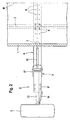
- 1 and 2 is from one to a vertical central longitudinal plane M essentially symmetrical truck only a vehicle body 1, in the example shown a platform and a side member 2 one in the rest Vehicle frame not shown shown on which the vehicle body 1 in a known, not shown Way is attached.
- a cross member 4 is arranged under the longitudinal beams 2.
- the cross member 4 has a in the example shown Double T profile (or H profile), with the top and the Undersides of the cross member 4 each by a flange Band 4 'are formed. At the free ends of the traverse 4 the bands 4 'are angled to taper the cross member 4, such that a wedge-shaped composite is formed, as can be seen from Fig. 1.
- Clamping elements 5 are used to fasten the cross member 4 which in addition to a non-positive connection, at least one positive connection in the transverse direction of the vehicle between the cross member 4 and the side members 2 becomes.
- the clamping elements 5 are shown in the drawing Embodiment on the upper band 4 'of the cross member 4th arranged and act with the lower band of the side members 2 of the vehicle frame together. These side members 2 typically have also a double T profile. To the traverse 4 on differently wide vehicle frames without further ado to be able to attach, are in the upper band 4 'of the cross member 4th 5 rows of holes 6 arranged for fastening the clamping elements, see. Fig. 2.
- the attachment supports 7 are set in such a way that that between structure 1 and attachment support 7 a certain Distance remains, which is only when the Body 1 or the truck or in driving tests with high Transverse forces is consumed.
- pendulum axle units 8 arranged with the support wheels 3.
- These swing axle units 8 have an axle support 9, which essentially made of two double T-profiles connected at right angles 9 'and 9 ".
- a bearing pin 11 can be inserted into these pin eyes 10 insert which for the hinge-like connection serves from axle carrier 9 and cross member 4 and on the one hand a bearing bush arranged at the free end of the cross member 4 12 and two bolt eyes 10 coaxial with it.
- the bearing pin 11 in further up or down on the double-T profile 9 " Bolt eyes 10 used, such that the double-T profile 9 'assumes an approximately horizontal position if that Jockey wheel 3 is mounted and a substantially load-free Condition of the cross member 4 and the support wheel 3 is present.
- the support wheel 3 is guided by a semiaxis 13. This is half of a non-driven one Front axle of a commercial truck. The other half of this front axle is used to guide the Other support wheel 3 not shown in the drawing.
- the support wheel 3 On the semi-axis 13, the support wheel 3 is arranged steerable. However, one of the semiaxis 13 is adjustable in length Tie rod 14 with its far end on the double-T profile 9 'of the axle bracket 19 attached so that the support wheel 3 not steerable, but with by changing the length of the tie rod 14 adjustable toe-in is held.
- the axle support 9 is via a hydraulic piston-cylinder unit 15, which is preferably double-acting is supported on the crossbar 4.
- a hydraulic piston-cylinder unit 15th Above the cross member 4, the unit 15 through the Wheel contact forces on the support wheel 3 are subjected to pressure.
- the axle side End of the unit 15 at the lower end of the double-T profile 9 "is articulated. In this case it will Unit 15 loaded by the wheel contact forces on train.
- the jockey wheel arrangement shown can have a track width in of the order of 5 m, so that in driving tests extreme lateral accelerations with the respective vehicle can be reached without the support wheel arrangement would cause the vehicle to tip over.
Landscapes
- Engineering & Computer Science (AREA)
- Mechanical Engineering (AREA)
- Vehicle Body Suspensions (AREA)
- Body Structure For Vehicles (AREA)
- Vehicle Cleaning, Maintenance, Repair, Refitting, And Outriggers (AREA)
Applications Claiming Priority (2)
| Application Number | Priority Date | Filing Date | Title |
|---|---|---|---|
| DE1999156785 DE19956785C1 (de) | 1999-11-25 | 1999-11-25 | Stützradanordnung |
| DE19956785 | 1999-11-25 |
Publications (2)
| Publication Number | Publication Date |
|---|---|
| EP1103393A2 true EP1103393A2 (fr) | 2001-05-30 |
| EP1103393A3 EP1103393A3 (fr) | 2002-03-13 |
Family
ID=7930316
Family Applications (1)
| Application Number | Title | Priority Date | Filing Date |
|---|---|---|---|
| EP00125766A Withdrawn EP1103393A3 (fr) | 1999-11-25 | 2000-11-24 | Agencement de support de roue |
Country Status (2)
| Country | Link |
|---|---|
| EP (1) | EP1103393A3 (fr) |
| DE (1) | DE19956785C1 (fr) |
Cited By (1)
| Publication number | Priority date | Publication date | Assignee | Title |
|---|---|---|---|---|
| DE202008015729U1 (de) * | 2008-11-28 | 2010-04-15 | Liebherr-Hydraulikbagger Gmbh | Abstützung für Mobilbagger |
Citations (2)
| Publication number | Priority date | Publication date | Assignee | Title |
|---|---|---|---|---|
| DE2823106B1 (de) | 1978-05-26 | 1979-02-22 | Opel Adam Ag | Messvorrichtung fuer den Lenkrollradius |
| DE3500904A1 (de) | 1985-01-12 | 1986-07-17 | Willy 7253 Renningen Stein | Vorrichtung und verfahren zur beeinflussung der fahrtrichtungshaltung von kraftfahrzeugen |
Family Cites Families (5)
| Publication number | Priority date | Publication date | Assignee | Title |
|---|---|---|---|---|
| US3397898A (en) * | 1967-02-06 | 1968-08-20 | Caterpillar Tractor Co | Stabilizer for motor vehicle |
| US3802720A (en) * | 1973-03-15 | 1974-04-09 | Brown R | Outrigger roll bar apparatus for tractor vehicles |
| DE2807518C3 (de) * | 1978-02-22 | 1981-09-24 | Habegger, Willy, Hünibach | Radaufhängung für ein Fahr- und Schreitwerk |
| US4998594A (en) * | 1989-12-04 | 1991-03-12 | Orloski John C | Vehicle control training device |
| DE19731089A1 (de) * | 1997-07-19 | 1999-01-21 | Bosch Gmbh Robert | Einrichtung zur Gewichtsbestimmung von angelenkten Lasten |
-
1999
- 1999-11-25 DE DE1999156785 patent/DE19956785C1/de not_active Expired - Fee Related
-
2000
- 2000-11-24 EP EP00125766A patent/EP1103393A3/fr not_active Withdrawn
Patent Citations (2)
| Publication number | Priority date | Publication date | Assignee | Title |
|---|---|---|---|---|
| DE2823106B1 (de) | 1978-05-26 | 1979-02-22 | Opel Adam Ag | Messvorrichtung fuer den Lenkrollradius |
| DE3500904A1 (de) | 1985-01-12 | 1986-07-17 | Willy 7253 Renningen Stein | Vorrichtung und verfahren zur beeinflussung der fahrtrichtungshaltung von kraftfahrzeugen |
Cited By (1)
| Publication number | Priority date | Publication date | Assignee | Title |
|---|---|---|---|---|
| DE202008015729U1 (de) * | 2008-11-28 | 2010-04-15 | Liebherr-Hydraulikbagger Gmbh | Abstützung für Mobilbagger |
Also Published As
| Publication number | Publication date |
|---|---|
| DE19956785C1 (de) | 2001-07-19 |
| EP1103393A3 (fr) | 2002-03-13 |
Similar Documents
| Publication | Publication Date | Title |
|---|---|---|
| EP2917070B1 (fr) | Véhicule de transport de charges lourdes servant au transport d'un objet allongé | |
| DE202012010545U1 (de) | Schwerlast-Transportfahrzeug zum Transport eines länglichen Objekts | |
| EP2246207B1 (fr) | Remorqueur d'aéroport doté d'une suspension à air | |
| EP2660127B1 (fr) | Unité de châssis et unité de module pour un chariot tracteur | |
| DE2363755C2 (de) | Gleisketten-Fahrzeug mit vier Gleisketteneinheiten | |
| DE102012021613B4 (de) | Schwerlast-Transportfahrzeug zum Transport eines länglichen Objekts | |
| DE19905676B4 (de) | Zugdeichsel für Zentralachsanhänger | |
| DE4227126A1 (de) | Gelenkverbindung zwischen zwei gelenkig miteinander verbundenen Fahrzeugen | |
| DE4444115C2 (de) | Mehrspuriges Leichtfahrzeug | |
| EP0678443B1 (fr) | Train de roulement, notamment pour machines de travail mobiles et véhicules | |
| EP0312556B1 (fr) | Chassis polyvalent pour vehicules utilitaires et speciaux | |
| DE4102884C2 (de) | Lenkanordnung für Raupenfahrwerke von Bandschleifenwagen | |
| DE2743077C2 (de) | Selbsttätig quergeführtes Fahrzeug, insbesondere für den öffentlichen Personennahverkehr | |
| DE4029288A1 (de) | Fahrzeug mit fahrwerk | |
| DE19956785C1 (de) | Stützradanordnung | |
| EP1122151A1 (fr) | Véhicule à plateau de chargement surbaissé extensible | |
| EP2875971B1 (fr) | Ensemble articulé pour un véhicule remorquer et au moins une remorque remorquée | |
| WO2002100755A1 (fr) | Chariot de manutention | |
| EP2780182A1 (fr) | Essieu rigide à suspension pneumatique | |
| EP4019301A1 (fr) | Dispositif d'essieu à écartement de la voie variable, véhicule spécial et son utilisation | |
| EP0225851B1 (fr) | Dispositif de suspension de roue pour un véhicule tous terrains à progression lente, en particulier pour voiture à traction par cheval | |
| DE4108333A1 (de) | Fahrzeug mit fahrwerk | |
| DE202004001249U1 (de) | Gezogener landwirtschaftlicher Wagen | |
| DE102012108527B4 (de) | Lastfahrzeug mit einem Schutzrahmen | |
| DE102018104320B4 (de) | Anbauvorrichtung |
Legal Events
| Date | Code | Title | Description |
|---|---|---|---|
| PUAI | Public reference made under article 153(3) epc to a published international application that has entered the european phase |
Free format text: ORIGINAL CODE: 0009012 |
|
| AK | Designated contracting states |
Kind code of ref document: A2 Designated state(s): AT BE CH CY DE DK ES FI FR GB GR IE IT LI LU MC NL PT SE TR |
|
| AX | Request for extension of the european patent |
Free format text: AL;LT;LV;MK;RO;SI |
|
| PUAL | Search report despatched |
Free format text: ORIGINAL CODE: 0009013 |
|
| AK | Designated contracting states |
Kind code of ref document: A3 Designated state(s): AT BE CH CY DE DK ES FI FR GB GR IE IT LI LU MC NL PT SE TR |
|
| AX | Request for extension of the european patent |
Free format text: AL;LT;LV;MK;RO;SI |
|
| RIC1 | Information provided on ipc code assigned before grant |
Free format text: 7B 60G 3/00 A, 7B 62D 17/00 B, 7B 60G 7/02 B, 7B 60G 3/06 B, 7B 66C 23/80 B, 7B 62D 49/08 B |
|
| AKX | Designation fees paid | ||
| REG | Reference to a national code |
Ref country code: DE Ref legal event code: 8566 |
|
| STAA | Information on the status of an ep patent application or granted ep patent |
Free format text: STATUS: THE APPLICATION IS DEEMED TO BE WITHDRAWN |
|
| 18D | Application deemed to be withdrawn |
Effective date: 20020914 |