EP1102016A1 - Heizkörper - Google Patents
Heizkörper Download PDFInfo
- Publication number
- EP1102016A1 EP1102016A1 EP99122832A EP99122832A EP1102016A1 EP 1102016 A1 EP1102016 A1 EP 1102016A1 EP 99122832 A EP99122832 A EP 99122832A EP 99122832 A EP99122832 A EP 99122832A EP 1102016 A1 EP1102016 A1 EP 1102016A1
- Authority
- EP
- European Patent Office
- Prior art keywords
- radiator
- elements
- terms
- fluidically
- flow technology
- Prior art date
- Legal status (The legal status is an assumption and is not a legal conclusion. Google has not performed a legal analysis and makes no representation as to the accuracy of the status listed.)
- Granted
Links
- 238000010438 heat treatment Methods 0.000 claims description 37
- 238000000034 method Methods 0.000 description 9
- 238000009826 distribution Methods 0.000 description 6
- 239000012080 ambient air Substances 0.000 description 5
- 239000012530 fluid Substances 0.000 description 4
- 239000000463 material Substances 0.000 description 2
- 230000002441 reversible effect Effects 0.000 description 2
- 238000003466 welding Methods 0.000 description 2
- 229910001369 Brass Inorganic materials 0.000 description 1
- RYGMFSIKBFXOCR-UHFFFAOYSA-N Copper Chemical compound [Cu] RYGMFSIKBFXOCR-UHFFFAOYSA-N 0.000 description 1
- 229910001209 Low-carbon steel Inorganic materials 0.000 description 1
- 239000003570 air Substances 0.000 description 1
- 229910052782 aluminium Inorganic materials 0.000 description 1
- XAGFODPZIPBFFR-UHFFFAOYSA-N aluminium Chemical compound [Al] XAGFODPZIPBFFR-UHFFFAOYSA-N 0.000 description 1
- 239000010951 brass Substances 0.000 description 1
- 230000000052 comparative effect Effects 0.000 description 1
- 229910052802 copper Inorganic materials 0.000 description 1
- 239000010949 copper Substances 0.000 description 1
- 230000000694 effects Effects 0.000 description 1
- 230000017525 heat dissipation Effects 0.000 description 1
- 230000004941 influx Effects 0.000 description 1
- 238000005304 joining Methods 0.000 description 1
- 238000004519 manufacturing process Methods 0.000 description 1
- 229910052751 metal Inorganic materials 0.000 description 1
- 239000002184 metal Substances 0.000 description 1
- 150000002739 metals Chemical class 0.000 description 1
- 239000002994 raw material Substances 0.000 description 1
- 230000000007 visual effect Effects 0.000 description 1
Images

Classifications
-
- F—MECHANICAL ENGINEERING; LIGHTING; HEATING; WEAPONS; BLASTING
- F24—HEATING; RANGES; VENTILATING
- F24D—DOMESTIC- OR SPACE-HEATING SYSTEMS, e.g. CENTRAL HEATING SYSTEMS; DOMESTIC HOT-WATER SUPPLY SYSTEMS; ELEMENTS OR COMPONENTS THEREFOR
- F24D19/00—Details
- F24D19/0002—Means for connecting central heating radiators to circulation pipes
- F24D19/0026—Places of the inlet on the radiator
- F24D19/0036—Places of the inlet on the radiator on the bottom in the middle
-
- F—MECHANICAL ENGINEERING; LIGHTING; HEATING; WEAPONS; BLASTING
- F24—HEATING; RANGES; VENTILATING
- F24D—DOMESTIC- OR SPACE-HEATING SYSTEMS, e.g. CENTRAL HEATING SYSTEMS; DOMESTIC HOT-WATER SUPPLY SYSTEMS; ELEMENTS OR COMPONENTS THEREFOR
- F24D19/00—Details
- F24D19/0002—Means for connecting central heating radiators to circulation pipes
- F24D19/0039—Places of the outlet on the radiator
- F24D19/0048—Places of the outlet on the radiator on the bottom in the middle
-
- F—MECHANICAL ENGINEERING; LIGHTING; HEATING; WEAPONS; BLASTING
- F24—HEATING; RANGES; VENTILATING
- F24D—DOMESTIC- OR SPACE-HEATING SYSTEMS, e.g. CENTRAL HEATING SYSTEMS; DOMESTIC HOT-WATER SUPPLY SYSTEMS; ELEMENTS OR COMPONENTS THEREFOR
- F24D19/00—Details
- F24D19/0002—Means for connecting central heating radiators to circulation pipes
- F24D19/0056—Supplies from the central heating system
- F24D19/0058—Supplies from the central heating system coming out the floor
- F24D19/0063—Supplies from the central heating system coming out the floor under the radiator
Definitions
- the present invention relates to a radiator with several Radiator elements, at least two the radiator elements in terms of fluid technology connecting connecting elements and at least one each on the Radiator fluidically connected inlet and an outlet for one heating medium flowing through the radiator.
- radiators are in multiple embodiments from the prior art Technology known and are used for heating different types of rooms used. In the majority of cases, such radiators are by means of a Heating medium circuit connected to a central heating system.
- This Central heating system is the heating medium flowing through the radiator by means of heat obtained by burning energy-rich raw materials, by means of heat generated by electrical energy, by means of heat exchange or on similarly warmed.
- the heating medium thus heated flows through Feed lines to the individual radiators and is via inlets into them brought in.
- the cooled heating medium, its in it emitted stored heat to the ambient air via the radiator is returned to via processes and return lines connected to them led to the central heating unit and begins its cycle again.
- the warm heating medium starting from the inlet to the radiator flows as evenly as possible and thus along the largest possible Surface heat gives off to the radiator, which this then to the Transmits ambient air. It is important to avoid using the warm heating medium along a short flow path presented to him in a direct way arrives at the drain and thus leaves the radiator without losing the inside of it stored amount of heat at the same and through this to the room air to have given up.
- a radiator equipped with such plugs is therefore complex to manufacture, since not only the plugs themselves are inserted into the pipe section to be closed have to be secured, but additionally secured against slipping Need to become.
- the present invention is based on the object of further developing a generic radiator in such a way that it has comparable flow properties with a comparatively simple structure.
- the present invention proposes that, in the case of a generic radiator, at least one of the radiator elements is connected fluidically only to a first of the connecting elements, and at least one further radiator element is fluidly connected exclusively to a second connecting element, that the remaining radiator elements in each case are connected in terms of flow technology and that the inlet to the radiator element (10a, 20a) which is connected only with the first of the connection elements (11a, 21a) and the outlet to the radiator element which is connected only with the second of the connection elements (11b, 21b) in terms of flow technology (10b, 20b) are connected directly or indirectly in terms of flow technology.
- a particularly advantageous arrangement of inlet and outlet results from that the at least one inflow to the only with the first Connection element fluidically connected radiator element directly is connected in terms of flow technology, whereas the process to the fluidically only with another connecting element connected radiator element is directly connected fluidically.
- the at least one inlet Connecting fluidic fluid connection element, not with all Radiator elements is fluidically connected, in the area of with this connecting element not connected radiator element.
- the process can either take place on the radiator element be connected fluidically that with that with the inlet fluidically connected flow element not fluidically connected or on the other, not with all radiator elements fluidically connected connecting elements.
- too Expiration and inflow in their arrangement described above are interchanged. The means that the position of the inlet described above by the outlet is taken and the position of the process described above by the Intake.
- radiator elements that are not are connected fluidically with all connecting elements, adjacent to arrange.
- An advantageous embodiment of the invention is both Radiator elements as well as the connecting elements to be tubular.
- the radiator elements can run essentially parallel, the Fasteners transverse to it in the end regions of the tubular Radiator elements run.
- the radiator elements can now be horizontal, vertical or arranged obliquely in the room.
- a particularly simple method of fluidically closing the individual components connect is that at the point of connection in the two too connecting elements holes, preferably bores, are provided, which lead from the outside into the flow channel and at superimposed arrangement a passage for the through Offer elements flowing heating medium.
- the individual elements of the radiator too mechanically connecting them consists of joining the elements along the as fluidic connection serving holes or holes To connect cross hole welds.
- the radiator elements with the connecting elements are not are connected in terms of flow, i.e. in places where not both Elements have holes or bores, one of the elements with a hole or a hole is provided, along which the cross hole weld can be made.
- this facilitates the mechanical Connect the individual elements and secondly ensures that a uniform visual appearance of the assembled radiator is guaranteed because the mechanical connection between the Fasteners and the radiator elements in the areas where this Elements not fluidically connected to each other, approximately the same the other mechanical connections can be carried out.
- the radiator 1 schematically shows an area of a radiator 1 in accordance with the invention shown a first embodiment.
- the radiator 1 consists of a plurality of tubular radiator elements 10, 10a, 10b arranged in parallel, which run in a substantially horizontal direction.
- Connecting elements 11 a, 11 b which with the radiator elements 10, 10a, 10 b are each mechanically connected.
- the radiator elements 10 are by means of Passage openings 14, each with two connecting elements 11 a, 11 b fluidically connected.
- the radiator element 10 a is only with the connecting element 11 a by means of a passage opening 14 fluidically connected, whereas it is in the area 16 with the Connecting element 11 b only mechanically, but not fluidically connected is.
- the reverse case applies to the radiator element 10b, which by means of a passage opening 14 exclusively with the connecting element 11 b is fluidly connected, whereas it is connected to the connecting element 11 a in the area 15 is only mechanically connected and none there has fluidic connection with the connecting element 11 a.
- An inlet 12 and an outlet 13 are with two of the radiator elements 10 a, 10 b connected.
- the inlet with the radiator element 10 a is by means of a Passage opening 17 fluidically connected, whereas the drain with another radiator element 10 b by means of a passage opening 18th is fluidly connected.
- the fact that the influx fluidically connected radiator element 10 a only with the Connecting element 11 a is connected in terms of flow technology causes the the inlet 12 flowing into the radiator 1, preheated heating medium from there initially only in the connecting element 11 a, which is also tubular is formed, can flow.
- the elements (radiator elements, connecting elements, inlet and outlet) of the in 1 are preferably made of one material manufactured with good thermal conductivity to match the preheated heating medium heat carried as completely as possible and with little loss to the ambient air to deliver.
- Metals with good thermal conductivity are particularly suitable for this, such as copper, aluminum, brass or low carbon steel.
- the preheated heating medium is fed through a feed line, not shown here the connection 12 out from where it in the radiator on the Radiator element 10 a arrives. Due to the lack of fluidic
- the warm heating medium is distributed in areas 15 and 16 over all radiator elements 10 and there gives the stored in it entrained heat at least partially to that surrounding the flow path Material of the radiator, from where this heat to the one to be heated Ambient air arrives.
- the heating medium cooled by heat dissipation arrives via a passage opening in the connecting element 11 b in the Radiator element 10 b and from there via the passage opening 18 to the Process 13, which in turn is connected to a return line, not shown here is.
- the feed line and the return line can be connected to a central Heating system connected in such a way that there is a closed circuit for the heating medium results.
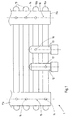
- FIG. 2 and 3 is another embodiment of an inventive Radiator shown.
- This radiator is basically similar to that shown in Fig. 1 horizontal, substantially parallel Radiator elements 20, 20a and 20b are two in their respective ones End regions perpendicular to these radiator elements, essentially vertically extending connecting elements 21 a and 21 b mechanically connected. Furthermore, an inlet 22 and an outlet 23 are also provided in this case, the respective flow to different radiator elements 20a and 20b are connected.
- the radiator elements consist of plate-shaped, tubular hollow bodies that run along their longer narrow edges are arranged one above the other.
- the radiator elements 20 are both with the connecting element 21a and the connecting element 21b Fluidically by means of two passage openings 24 fluidically connected.
- radiator element 21a and that Radiator element 20b are each with only one of the connecting elements fluidically connected.
- the radiator element 20a is only included the connecting element 21a by means of two passage openings 24 fluidly connected, whereas it to the connecting element 21b has no fluidic connections.
- the radiator element 20b is fluidically only with the connecting element 21b two through openings 24 connected, whereas it to the Connecting elements 21a no direct fluid connection owns.
- the operating principle of the radiator from Fig. 2 is analogous to that of Radiator from Fig. 1. Due to the fact that the inlet 22nd fluidically connected radiator element 20a only with the Connection element 21a is fluidly connected, whereas that with the radiator element 20b connected to the flow 23 only with is connected to the connecting element 21b in terms of flow technology, a effective distribution of the preheated heating medium in the radiator.
- Figs. 2 and 3 showing the second embodiment are still on Brackets 29, 210, 211, 212 fastened to the radiator elements 20 and 20a, respectively recognize by means of which the radiator according to the invention, for example on a Wall can be attached.
- To vent or to drain the in the Radiator heating medium are on the connecting element 21a Valves 213 and 214 arranged.
- the passage openings are one in both embodiments Radiator according to the invention in the form of hole-like openings in the elements to be connected to one another in terms of flow technology.
- the too connecting elements are congruent along the circumference of the so mechanically overlapped openings by means of cross hole welding connected, so that on the one hand the fluidic connection to the outside is sealed and thus the heating medium does not leak out of the radiator can and that on the other hand the mechanical connection is guaranteed.
- the Hole-like openings can, for example, be drilled or punched into the individual Elements are introduced.
- the flow direction in both embodiments of the preheated heating medium is in principle reversible. That means that in the case of the first embodiment, the drain 13 serves as an inflow, whereas the Inflow 12 is used as an outflow.
- the inflow 22 can be used as an outflow and the outflow 23 can also be used as an inflow, without the distribution of the heating medium in the individual radiator elements is affected by it.
- radiator elements should not be arranged horizontally but vertically. They can also Radiator elements each in different, non-parallel directions run. Also within the scope of this invention is a radiator in which the Radiator elements and the connecting elements in large, contiguous components have been impressed by forming. Except The embodiments shown are thus a multitude of others Embodiments of a radiator according to the invention are conceivable.
Landscapes
- Engineering & Computer Science (AREA)
- Physics & Mathematics (AREA)
- Thermal Sciences (AREA)
- Chemical & Material Sciences (AREA)
- Combustion & Propulsion (AREA)
- Mechanical Engineering (AREA)
- General Engineering & Computer Science (AREA)
- Steam Or Hot-Water Central Heating Systems (AREA)
- Surgical Instruments (AREA)
- Cooling, Air Intake And Gas Exhaust, And Fuel Tank Arrangements In Propulsion Units (AREA)
- Central Heating Systems (AREA)
Abstract
Description
- Fig. 1
- eine Ansicht eines Teilbereichs eines ersten Ausführungsbeispieles eines erfindungsgemäßen Heizkörpers,
- Fig. 2
- eine entlang der Breite der Erstreckung unterbrochene Ansicht eines zweiten Ausführungsbeispieles eines erfindungsgemäßen Heizkörpers und
- Fig. 3
- eine Aufsicht auf den Heizkörper aus Fig. 2.
- 1
- Heizkörper
- 10
- Radiatorelement
- 10a
- Radiatorelement
- 10b
- Radiatorelement
- 11a
- Verbindungselement
- 11b
- Verbindungselement
- 12
- Zulauf
- 13
- Ablauf
- 14
- Durchlaßöffnung
- 15
- Bereich
- 16
- Bereich
- 17
- Durchlaßöffnung
- 18
- Durchlaßöffnung
- 2
- Heizkörper
- 20
- Radiatorelement
- 20a
- Radiatorelement
- 20b
- Radiatorelement
- 21a
- Verbindungselement
- 21b
- Verbindungselement
- 22
- Zulauf
- 23
- Ablauf
- 24
- Durchlaßöffnung
- 25
- Bereich
- 26
- Bereich
- 27
- Durchlaßöffnung
- 28
- Durchlaßöffnung
- 29
- Halterung
- 210
- Halterung
- 211
- Halterung
- 212
- Halterung
- 213
- Ventil
- 214
- Ventil
Claims (11)
- Heizkörper mit:dadurch gekennzeichnet,mehreren Radiatorelementen (10, 10a, 10b, 20, 20a, 20b) mindestens zwei die Radiatorelemente (10, 10a, 10b, 20, 20a, 20b) strömungstechnisch verbindende Verbindungselementen (11a, 11b, 21a, 21b) sowiemindestens je einem an dem Heizkörper (1,2) strömungstechnisch angeschlossenen Zulauf (12, 22) und einem Ablauf (13, 23) für ein den Heizkörper (1, 2) durchströmendes Heizmedium,
daß wenigstens eines der Radiatorelemente (10a, 20a) ausschließlich mit einem ersten der Verbindungselemente (11a, 21a) strömungstechnisch verbunden ist, mindestens ein weiteres der Radiatorelemente (10b, 20b) ausschließlich mit einem zweiten der Verbindungselemente (11b, 21b) strömungstechnisch verbunden ist, daß die verbleibenden Radiatorelemente (10, 20) jeweils mit allen Verbindungselementen (11a, 11b) strömungstechnisch verbunden sind und daß der Zulauf (12, 22) an das ausschließlich mit dem ersten der Verbindungselemente (11a, 21a) strömungstechnisch verbundene Radiatorelement (10a, 20a) und der Ablauf (13, 23) an das ausschließlich mit dem zweiten der Verbindungselemente (11b, 21b) strömungstechnisch verbundene Radiatorelement (10b, 20b) direkt oder indirekt strömungstechnisch angeschlossen sind. - Heizkörper nach Anspruch 1, dadurch gekennzeichnet, daß der mindestens eine Zulauf (12, 22) an das ausschließlich mit dem ersten Verbindungselement (11a, 21a) strömungstechnisch verbundene Radiatorelement (10a, 20a) direkt strömungstechnisch angeschlossen ist, wohingegen der Ablauf (13, 23) an das ausschließlich mit einem zweiten Verbindungselement (11b, 21b) strömungstechnisch verbundene Radiatorelement (10b, 20b) direkt strömungstechnisch angeschlossen ist.
- Heizkörper nach Anspruch 1, dadurch gekennzeichnet, daß der Zulauf (12, 22) an ein Verbindungselement (11a, 21a) in einem Bereich (15, 26) angeschlossen ist, in dem dieses Verbindungselement (11a, 21a) mit einem mechanisch mit diesem verbundenen Radiatorelement (10b, 20b) strömungstechnisch nicht verbunden ist, und daß der Ablauf (13, 23) an ein weiteres Verbindungselement, (11b, 21b) in einem Bereich, in dem dieses Verbindungselement, (11b, 21b) mit einem Radiatorelement (10a, 20a) mechanisch jedoch nicht strömungstechnisch verbunden ist, angeschlossen ist.
- Heizkörper nach einem der vorhergehenden Ansprüche, dadurch gekennzeichnet, daß die Radiatorelemente (10a, 10b, 20a, 20b), die nicht mit allen Verbindungselementen strömungstechnisch verbunden sind, benachbart angeordnet sind.
- Heizkörper nach einem der vorhergehenden Ansprüche, dadurch gekennzeichnet, daß sowohl Radiatorelemente (10, 10a, 10b, 20, 20a, 20b) als auch Verbindungselemente (11a, 11b, 21a, 21b) rohrförmig ausgebildet sind.
- Heizkörper nach einem der vorhergehenden Ansprüche, dadurch gekennzeichnet, daß die Radiatorelemente (10, 10a, 10b, 20, 20a, 20b) im wesentlichen parallel verlaufen, wobei die Verbindungselemente (11a, 11b, 21a, 21b) jeweils in den Endbereichen der Radiatorelemente (10, 10a, 10b, 20, 20a, 20b) quer zu diesen verlaufen.
- Heizkörper nach einem der vorhergehenden Ansprüche, dadurch gekennzeichnet, daß die Radiatorelemente (10, 10a, 10b, 20, 20a, 20b) sich in im wesentlichen horizontaler Richtung erstrecken.
- Heizkörper nach einem der vorhergehenden Ansprüche, dadurch gekennzeichnet, daß die Radiatorelemente (10, 10a, 10b, 20, 20a, 20b) sich in im wesentlichen vertikaler Richtung erstrecken.
- Heizkörper nach einem der vorhergehenden Ansprüche, dadurch gekennzeichnet, daß zur strömungstechnischen Verbindung der einzelnen Bauteil Löcher (14, 17, 18, 24, 27, 28) in diesen vorgesehen sind, welche von außen in den Strömungskanal führen.
- Heizkörper nach einem der vorhergehenden Ansprüche, dadurch gekennzeichnet, daß zur mechanischen Verbindung der einzelnen Elemente diese entlang der als strömungstechnische Verbindung dienenden Löcher (14, 17, 18, 24, 27, 28) mit Kreuzlochschweißungen verbunden werden.
- Heizkörper nach einem der vorhergehenden Ansprüche, dadurch gekennzeichnet, daß in den Bereichen (15, 16, 25, 26), in denen ein Radiatorelement (10a, 10b, 20a, 20b) mit einem Verbindungselement (11a, 11b, 21a, 21b) nicht strömungstechnisch verbunden ist, eines der oben genannten Elemente ein Loch aufweist.
Priority Applications (6)
| Application Number | Priority Date | Filing Date | Title |
|---|---|---|---|
| ES99122832T ES2194413T3 (es) | 1999-11-17 | 1999-11-17 | Radiador. |
| DE29924166U DE29924166U1 (de) | 1999-11-17 | 1999-11-17 | Heizkörper |
| DE59904550T DE59904550D1 (de) | 1999-11-17 | 1999-11-17 | Heizkörper |
| DK99122832T DK1102016T3 (da) | 1999-11-17 | 1999-11-17 | Radiator |
| EP99122832A EP1102016B1 (de) | 1999-11-17 | 1999-11-17 | Heizkörper |
| AT99122832T ATE234446T1 (de) | 1999-11-17 | 1999-11-17 | Heizkörper |
Applications Claiming Priority (1)
| Application Number | Priority Date | Filing Date | Title |
|---|---|---|---|
| EP99122832A EP1102016B1 (de) | 1999-11-17 | 1999-11-17 | Heizkörper |
Publications (2)
| Publication Number | Publication Date |
|---|---|
| EP1102016A1 true EP1102016A1 (de) | 2001-05-23 |
| EP1102016B1 EP1102016B1 (de) | 2003-03-12 |
Family
ID=8239409
Family Applications (1)
| Application Number | Title | Priority Date | Filing Date |
|---|---|---|---|
| EP99122832A Expired - Lifetime EP1102016B1 (de) | 1999-11-17 | 1999-11-17 | Heizkörper |
Country Status (5)
| Country | Link |
|---|---|
| EP (1) | EP1102016B1 (de) |
| AT (1) | ATE234446T1 (de) |
| DE (1) | DE59904550D1 (de) |
| DK (1) | DK1102016T3 (de) |
| ES (1) | ES2194413T3 (de) |
Cited By (1)
| Publication number | Priority date | Publication date | Assignee | Title |
|---|---|---|---|---|
| EP1371916A3 (de) * | 2002-06-14 | 2004-09-22 | Zehnder Verkaufs- und Verwaltungs AG | Heizkörperanschlussvorrichtung |
Citations (4)
| Publication number | Priority date | Publication date | Assignee | Title |
|---|---|---|---|---|
| GB1432490A (en) * | 1972-06-30 | 1976-04-14 | Hammarstedt C L | Radiator |
| DE9102265U1 (de) | 1991-02-26 | 1991-05-16 | Zehnder-Beutler GmbH, 7630 Lahr | Wärmekörper |
| DE29519417U1 (de) * | 1994-12-07 | 1996-06-05 | Vogel & Noot Wärmetechnik AG, Wartberg | Heizkörper mit im wesentlichen rohrartiger Zuführung und Abführung für ein Wärmeträgerfluid |
| EP0928939A2 (de) * | 1998-01-09 | 1999-07-14 | N.V. Vasco | Röhrenheizkörper mit innerem Rohr |
-
1999
- 1999-11-17 DK DK99122832T patent/DK1102016T3/da active
- 1999-11-17 DE DE59904550T patent/DE59904550D1/de not_active Expired - Lifetime
- 1999-11-17 EP EP99122832A patent/EP1102016B1/de not_active Expired - Lifetime
- 1999-11-17 ES ES99122832T patent/ES2194413T3/es not_active Expired - Lifetime
- 1999-11-17 AT AT99122832T patent/ATE234446T1/de active
Patent Citations (4)
| Publication number | Priority date | Publication date | Assignee | Title |
|---|---|---|---|---|
| GB1432490A (en) * | 1972-06-30 | 1976-04-14 | Hammarstedt C L | Radiator |
| DE9102265U1 (de) | 1991-02-26 | 1991-05-16 | Zehnder-Beutler GmbH, 7630 Lahr | Wärmekörper |
| DE29519417U1 (de) * | 1994-12-07 | 1996-06-05 | Vogel & Noot Wärmetechnik AG, Wartberg | Heizkörper mit im wesentlichen rohrartiger Zuführung und Abführung für ein Wärmeträgerfluid |
| EP0928939A2 (de) * | 1998-01-09 | 1999-07-14 | N.V. Vasco | Röhrenheizkörper mit innerem Rohr |
Cited By (1)
| Publication number | Priority date | Publication date | Assignee | Title |
|---|---|---|---|---|
| EP1371916A3 (de) * | 2002-06-14 | 2004-09-22 | Zehnder Verkaufs- und Verwaltungs AG | Heizkörperanschlussvorrichtung |
Also Published As
| Publication number | Publication date |
|---|---|
| DK1102016T3 (da) | 2003-07-14 |
| ES2194413T3 (es) | 2003-11-16 |
| ATE234446T1 (de) | 2003-03-15 |
| DE59904550D1 (de) | 2003-04-17 |
| EP1102016B1 (de) | 2003-03-12 |
Similar Documents
| Publication | Publication Date | Title |
|---|---|---|
| DE19519740B4 (de) | Wärmetauscher | |
| DE19719251A1 (de) | Verteil-/Sammel-Kasten eines mindestens zweiflutigen Verdampfers einer Kraftfahrzeugklimaanlage | |
| EP1306638A2 (de) | Gehäuseloser Plattenwärmetauscher | |
| DE4404922C1 (de) | Peripher gebohrte Walze zur Wärmebehandlung von Bahnmaterial | |
| EP0256259B1 (de) | Wärmetauscher, insbesondere Kältemittel-Verdampfer | |
| DE3824073C2 (de) | Ölkühler | |
| DE69716214T2 (de) | Gliederheizkessel und Heizgerät mit so einem Kessel | |
| DE20104315U1 (de) | Anschlußteil für einen Heizkörper sowie Heizkörperanordnung | |
| EP1102016A1 (de) | Heizkörper | |
| DE3533196C2 (de) | ||
| EP2035757A1 (de) | Heizkörper, insbesondere röhrenradiator | |
| EP1725823A1 (de) | Vorrichtung zum austausch von wärme und verfahren zur herstellung einer solchen vorrichtung | |
| EP1553363B1 (de) | Heiz- bzw. Kühlkörper-Verteileranordnung | |
| DE202005015627U1 (de) | Wärmeaustauschernetz und damit ausgerüsteter Wärmeaustauscher | |
| DE29924166U1 (de) | Heizkörper | |
| DE102017204492A1 (de) | Wärmetauscher für eine Schmelzflusselektrolysezelle | |
| DE10150987B4 (de) | Verfahren zum Verlegen einer Matte mit dünnwandigen Kunststoffrohren | |
| DE2142621A1 (de) | Verbindung von rechteckprofilen | |
| DE102007035817B4 (de) | Röhrenradiator | |
| DE7115268U (de) | Wärmetauscher mit parallel zueinander angeordneten Flachrohren | |
| CH532238A (de) | Heizwand für mit flüssigen Wärmemedien betriebene Heizanlagen und Verfahren zu ihrer Herstellung | |
| DE1945436B2 (de) | Vorrichtung zum kuehlen des giessrades einer stranggiessvorrichtung | |
| DE2623632A1 (de) | Heizkessel mit liegenden kesselgliedern | |
| EP1316762A2 (de) | Durchlauferhitzer | |
| DE10105373A1 (de) | Verbesserter Heizkörper |
Legal Events
| Date | Code | Title | Description |
|---|---|---|---|
| PUAI | Public reference made under article 153(3) epc to a published international application that has entered the european phase |
Free format text: ORIGINAL CODE: 0009012 |
|
| 17P | Request for examination filed |
Effective date: 20000519 |
|
| AK | Designated contracting states |
Kind code of ref document: A1 Designated state(s): AT BE CH CY DE DK ES FI FR GB GR IE IT LI LU MC NL PT SE |
|
| AX | Request for extension of the european patent |
Free format text: AL;LT;LV;MK;RO;SI |
|
| AKX | Designation fees paid |
Free format text: AT BE CH CY DE DK ES FI FR GB GR IE IT LI LU MC NL PT SE |
|
| 17Q | First examination report despatched |
Effective date: 20020307 |
|
| GRAH | Despatch of communication of intention to grant a patent |
Free format text: ORIGINAL CODE: EPIDOS IGRA |
|
| GRAH | Despatch of communication of intention to grant a patent |
Free format text: ORIGINAL CODE: EPIDOS IGRA |
|
| GRAA | (expected) grant |
Free format text: ORIGINAL CODE: 0009210 |
|
| AK | Designated contracting states |
Designated state(s): AT BE CH CY DE DK ES FI FR GB GR IE IT LI LU MC NL PT SE |
|
| PG25 | Lapsed in a contracting state [announced via postgrant information from national office to epo] |
Ref country code: GR Free format text: LAPSE BECAUSE OF FAILURE TO SUBMIT A TRANSLATION OF THE DESCRIPTION OR TO PAY THE FEE WITHIN THE PRESCRIBED TIME-LIMIT Effective date: 20030312 |
|
| REG | Reference to a national code |
Ref country code: GB Ref legal event code: FG4D Free format text: NOT ENGLISH |
|
| REG | Reference to a national code |
Ref country code: CH Ref legal event code: EP |
|
| REG | Reference to a national code |
Ref country code: IE Ref legal event code: FG4D Free format text: GERMAN |
|
| REF | Corresponds to: |
Ref document number: 59904550 Country of ref document: DE Date of ref document: 20030417 Kind code of ref document: P |
|
| REG | Reference to a national code |
Ref country code: CH Ref legal event code: NV Representative=s name: E. BLUM & CO. PATENTANWAELTE |
|
| GBT | Gb: translation of ep patent filed (gb section 77(6)(a)/1977) |
Effective date: 20030516 |
|
| PG25 | Lapsed in a contracting state [announced via postgrant information from national office to epo] |
Ref country code: PT Free format text: LAPSE BECAUSE OF FAILURE TO SUBMIT A TRANSLATION OF THE DESCRIPTION OR TO PAY THE FEE WITHIN THE PRESCRIBED TIME-LIMIT Effective date: 20030616 |
|
| REG | Reference to a national code |
Ref country code: SE Ref legal event code: TRGR |
|
| REG | Reference to a national code |
Ref country code: DK Ref legal event code: T3 |
|
| ET | Fr: translation filed | ||
| REG | Reference to a national code |
Ref country code: ES Ref legal event code: FG2A Ref document number: 2194413 Country of ref document: ES Kind code of ref document: T3 |
|
| PG25 | Lapsed in a contracting state [announced via postgrant information from national office to epo] |
Ref country code: CY Free format text: LAPSE BECAUSE OF FAILURE TO SUBMIT A TRANSLATION OF THE DESCRIPTION OR TO PAY THE FEE WITHIN THE PRESCRIBED TIME-LIMIT Effective date: 20031117 |
|
| PG25 | Lapsed in a contracting state [announced via postgrant information from national office to epo] |
Ref country code: MC Free format text: LAPSE BECAUSE OF NON-PAYMENT OF DUE FEES Effective date: 20031130 |
|
| PLBQ | Unpublished change to opponent data |
Free format text: ORIGINAL CODE: EPIDOS OPPO |
|
| PLBI | Opposition filed |
Free format text: ORIGINAL CODE: 0009260 |
|
| PLAX | Notice of opposition and request to file observation + time limit sent |
Free format text: ORIGINAL CODE: EPIDOSNOBS2 |
|
| 26 | Opposition filed |
Opponent name: VOGEL & NOOT WAEREMTECHNIK AKTIENGESELLSCHAFT Effective date: 20031212 |
|
| NLR1 | Nl: opposition has been filed with the epo |
Opponent name: VOGEL & NOOT WAEREMTECHNIK AKTIENGESELLSCHAFT |
|
| PLAX | Notice of opposition and request to file observation + time limit sent |
Free format text: ORIGINAL CODE: EPIDOSNOBS2 |
|
| PLBB | Reply of patent proprietor to notice(s) of opposition received |
Free format text: ORIGINAL CODE: EPIDOSNOBS3 |
|
| PLCK | Communication despatched that opposition was rejected |
Free format text: ORIGINAL CODE: EPIDOSNREJ1 |
|
| PLBN | Opposition rejected |
Free format text: ORIGINAL CODE: 0009273 |
|
| STAA | Information on the status of an ep patent application or granted ep patent |
Free format text: STATUS: OPPOSITION REJECTED |
|
| 27O | Opposition rejected |
Effective date: 20050425 |
|
| NLR2 | Nl: decision of opposition |
Effective date: 20050425 |
|
| REG | Reference to a national code |
Ref country code: CH Ref legal event code: PFA Owner name: ZEHNDER VERKAUFS- UND VERWALTUNGS AG Free format text: ZEHNDER VERKAUFS- UND VERWALTUNGS AG#MOORTALSTRASSE 1#5722 GRAENICHEN (CH) -TRANSFER TO- ZEHNDER VERKAUFS- UND VERWALTUNGS AG#MOORTALSTRASSE 1#5722 GRAENICHEN (CH) |
|
| PGFP | Annual fee paid to national office [announced via postgrant information from national office to epo] |
Ref country code: LU Payment date: 20111130 Year of fee payment: 13 Ref country code: DK Payment date: 20111118 Year of fee payment: 13 Ref country code: IE Payment date: 20111118 Year of fee payment: 13 Ref country code: FI Payment date: 20111114 Year of fee payment: 13 Ref country code: SE Payment date: 20111128 Year of fee payment: 13 Ref country code: NL Payment date: 20111124 Year of fee payment: 13 |
|
| REG | Reference to a national code |
Ref country code: NL Ref legal event code: V1 Effective date: 20130601 |
|
| REG | Reference to a national code |
Ref country code: DK Ref legal event code: EBP |
|
| PG25 | Lapsed in a contracting state [announced via postgrant information from national office to epo] |
Ref country code: SE Free format text: LAPSE BECAUSE OF NON-PAYMENT OF DUE FEES Effective date: 20121118 |
|
| REG | Reference to a national code |
Ref country code: IE Ref legal event code: MM4A |
|
| PG25 | Lapsed in a contracting state [announced via postgrant information from national office to epo] |
Ref country code: FI Free format text: LAPSE BECAUSE OF NON-PAYMENT OF DUE FEES Effective date: 20121117 Ref country code: NL Free format text: LAPSE BECAUSE OF NON-PAYMENT OF DUE FEES Effective date: 20130601 |
|
| PG25 | Lapsed in a contracting state [announced via postgrant information from national office to epo] |
Ref country code: DK Free format text: LAPSE BECAUSE OF NON-PAYMENT OF DUE FEES Effective date: 20121130 Ref country code: IE Free format text: LAPSE BECAUSE OF NON-PAYMENT OF DUE FEES Effective date: 20121117 |
|
| PG25 | Lapsed in a contracting state [announced via postgrant information from national office to epo] |
Ref country code: LU Free format text: LAPSE BECAUSE OF NON-PAYMENT OF DUE FEES Effective date: 20121117 |
|
| PGFP | Annual fee paid to national office [announced via postgrant information from national office to epo] |
Ref country code: AT Payment date: 20141027 Year of fee payment: 16 |
|
| REG | Reference to a national code |
Ref country code: FR Ref legal event code: PLFP Year of fee payment: 17 |
|
| REG | Reference to a national code |
Ref country code: AT Ref legal event code: MM01 Ref document number: 234446 Country of ref document: AT Kind code of ref document: T Effective date: 20151117 |
|
| PG25 | Lapsed in a contracting state [announced via postgrant information from national office to epo] |
Ref country code: AT Free format text: LAPSE BECAUSE OF NON-PAYMENT OF DUE FEES Effective date: 20151117 |
|
| REG | Reference to a national code |
Ref country code: FR Ref legal event code: PLFP Year of fee payment: 18 |
|
| REG | Reference to a national code |
Ref country code: CH Ref legal event code: PFUS Owner name: ZEHNDER GROUP INTERNATIONAL AG, CH Free format text: FORMER OWNER: ZEHNDER VERKAUFS- UND VERWALTUNGS AG, CH |
|
| REG | Reference to a national code |
Ref country code: GB Ref legal event code: 732E Free format text: REGISTERED BETWEEN 20170817 AND 20170823 |
|
| REG | Reference to a national code |
Ref country code: ES Ref legal event code: PC2A Owner name: ZEHNDER GROUP INTERNATIONAL AG Effective date: 20170926 |
|
| REG | Reference to a national code |
Ref country code: DE Ref legal event code: R082 Ref document number: 59904550 Country of ref document: DE Representative=s name: RAUSCH WANISCHECK-BERGMANN BRINKMANN PARTNERSC, DE Ref country code: DE Ref legal event code: R082 Ref document number: 59904550 Country of ref document: DE Representative=s name: STENGER WATZKE RING INTELLECTUAL PROPERTY, DE Ref country code: DE Ref legal event code: R081 Ref document number: 59904550 Country of ref document: DE Owner name: ZEHNDER GROUP INTERNATIONAL AG, CH Free format text: FORMER OWNER: ZEHNDER VERKAUFS- UND VERWALTUNGS-AG, GRAENICHEN, CH |
|
| REG | Reference to a national code |
Ref country code: FR Ref legal event code: TP Owner name: ZEHNDER GROUP INTERNATIONAL AG, CH Effective date: 20171009 |
|
| REG | Reference to a national code |
Ref country code: FR Ref legal event code: PLFP Year of fee payment: 19 |
|
| REG | Reference to a national code |
Ref country code: DE Ref legal event code: R082 Ref document number: 59904550 Country of ref document: DE Representative=s name: BRINKMANN & PARTNER PATENTANWAELTE PARTNERSCHA, DE Ref country code: DE Ref legal event code: R082 Ref document number: 59904550 Country of ref document: DE Representative=s name: RAUSCH WANISCHECK-BERGMANN BRINKMANN PARTNERSC, DE |
|
| PGFP | Annual fee paid to national office [announced via postgrant information from national office to epo] |
Ref country code: DE Payment date: 20181120 Year of fee payment: 20 |
|
| PGFP | Annual fee paid to national office [announced via postgrant information from national office to epo] |
Ref country code: GB Payment date: 20181120 Year of fee payment: 20 Ref country code: CH Payment date: 20181120 Year of fee payment: 20 Ref country code: FR Payment date: 20181123 Year of fee payment: 20 Ref country code: IT Payment date: 20181126 Year of fee payment: 20 Ref country code: BE Payment date: 20181120 Year of fee payment: 20 Ref country code: ES Payment date: 20181218 Year of fee payment: 20 |
|
| REG | Reference to a national code |
Ref country code: DE Ref legal event code: R071 Ref document number: 59904550 Country of ref document: DE |
|
| REG | Reference to a national code |
Ref country code: CH Ref legal event code: PL |
|
| REG | Reference to a national code |
Ref country code: GB Ref legal event code: PE20 Expiry date: 20191116 |
|
| REG | Reference to a national code |
Ref country code: BE Ref legal event code: MK Effective date: 20191117 |
|
| PG25 | Lapsed in a contracting state [announced via postgrant information from national office to epo] |
Ref country code: GB Free format text: LAPSE BECAUSE OF EXPIRATION OF PROTECTION Effective date: 20191116 |
|
| REG | Reference to a national code |
Ref country code: ES Ref legal event code: FD2A Effective date: 20210111 |
|
| PG25 | Lapsed in a contracting state [announced via postgrant information from national office to epo] |
Ref country code: ES Free format text: LAPSE BECAUSE OF EXPIRATION OF PROTECTION Effective date: 20191118 |