EP1101912B1 - Schalldämpfer mit Aussen- und Innenhalbschalen - Google Patents
Schalldämpfer mit Aussen- und Innenhalbschalen Download PDFInfo
- Publication number
- EP1101912B1 EP1101912B1 EP01103995A EP01103995A EP1101912B1 EP 1101912 B1 EP1101912 B1 EP 1101912B1 EP 01103995 A EP01103995 A EP 01103995A EP 01103995 A EP01103995 A EP 01103995A EP 1101912 B1 EP1101912 B1 EP 1101912B1
- Authority
- EP
- European Patent Office
- Prior art keywords
- shell
- shells
- silencer
- inner half
- angled
- Prior art date
- Legal status (The legal status is an assumption and is not a legal conclusion. Google has not performed a legal analysis and makes no representation as to the accuracy of the status listed.)
- Expired - Lifetime
Links
Images
Classifications
-
- F—MECHANICAL ENGINEERING; LIGHTING; HEATING; WEAPONS; BLASTING
- F01—MACHINES OR ENGINES IN GENERAL; ENGINE PLANTS IN GENERAL; STEAM ENGINES
- F01N—GAS-FLOW SILENCERS OR EXHAUST APPARATUS FOR MACHINES OR ENGINES IN GENERAL; GAS-FLOW SILENCERS OR EXHAUST APPARATUS FOR INTERNAL-COMBUSTION ENGINES
- F01N13/00—Exhaust or silencing apparatus characterised by constructional features
- F01N13/18—Construction facilitating manufacture, assembly, or disassembly
- F01N13/1872—Construction facilitating manufacture, assembly, or disassembly the assembly using stamp-formed parts or otherwise deformed sheet-metal
-
- F—MECHANICAL ENGINEERING; LIGHTING; HEATING; WEAPONS; BLASTING
- F01—MACHINES OR ENGINES IN GENERAL; ENGINE PLANTS IN GENERAL; STEAM ENGINES
- F01N—GAS-FLOW SILENCERS OR EXHAUST APPARATUS FOR MACHINES OR ENGINES IN GENERAL; GAS-FLOW SILENCERS OR EXHAUST APPARATUS FOR INTERNAL-COMBUSTION ENGINES
- F01N13/00—Exhaust or silencing apparatus characterised by constructional features
- F01N13/18—Construction facilitating manufacture, assembly, or disassembly
- F01N13/1838—Construction facilitating manufacture, assembly, or disassembly characterised by the type of connection between parts of exhaust or silencing apparatus, e.g. between housing and tubes, between tubes and baffles
- F01N13/1844—Mechanical joints
- F01N13/185—Mechanical joints the connection being realised by deforming housing, tube, baffle, plate, or parts thereof
-
- F—MECHANICAL ENGINEERING; LIGHTING; HEATING; WEAPONS; BLASTING
- F01—MACHINES OR ENGINES IN GENERAL; ENGINE PLANTS IN GENERAL; STEAM ENGINES
- F01N—GAS-FLOW SILENCERS OR EXHAUST APPARATUS FOR MACHINES OR ENGINES IN GENERAL; GAS-FLOW SILENCERS OR EXHAUST APPARATUS FOR INTERNAL-COMBUSTION ENGINES
- F01N13/00—Exhaust or silencing apparatus characterised by constructional features
- F01N13/18—Construction facilitating manufacture, assembly, or disassembly
- F01N13/1888—Construction facilitating manufacture, assembly, or disassembly the housing of the assembly consisting of two or more parts, e.g. two half-shells
-
- F—MECHANICAL ENGINEERING; LIGHTING; HEATING; WEAPONS; BLASTING
- F01—MACHINES OR ENGINES IN GENERAL; ENGINE PLANTS IN GENERAL; STEAM ENGINES
- F01N—GAS-FLOW SILENCERS OR EXHAUST APPARATUS FOR MACHINES OR ENGINES IN GENERAL; GAS-FLOW SILENCERS OR EXHAUST APPARATUS FOR INTERNAL-COMBUSTION ENGINES
- F01N2450/00—Methods or apparatus for fitting, inserting or repairing different elements
- F01N2450/24—Methods or apparatus for fitting, inserting or repairing different elements by bolts, screws, rivets or the like
Definitions
- the invention relates to a silencer according to the preamble of claim 1.
- JP 07 293234 A discloses a silencer, in the only edge of one of two sheet metal sheets in a single stage Perimeter fold is taken bent and the edge of the other Tray plate is only trapped in the fold.
- the object of the invention is the enrichment of the state of Technology by creating a silencer of the beginning mentioned type in which simple means a flawless Attachment between the shells with less Leakage rate is given.
- the muffler has an upper and a lower outer half shell and an upper and a lower inner half-shell, Preferably, the peripheral fold is angled downwards.
- the shell fastening is made so that only the edge of an inner half-shell in the angled medicinalsfalz the outer half shells taken bent and the rectilinear edge of the other inner half shell is clamped in the circumferential fold.
- EP 0 664 380 A1 discloses an angled peripheral fold a built-up of shells muffler known. Of the However, angled circumferential fold is only between the outer shells educated. The inner shells, however, lie with their not angled edge in a resilient connection in individual spaced apart terminal beads of the outer shells outside the peripheral fold. The terminal beads mean on the one hand a complex production and the other part a labile attachment between the shells. A fixation between inner and outer shells is not sufficiently ensured. If not properly clamped connection or material fatigue occurs in the area of the clamping beads loose connection between the items one with the result of rattling noises of a muffler in operation.
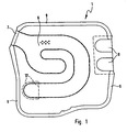
- an absorption / reflection muffler 1 of a motor vehicle an outer housing and an inner housing in half-shell technique consisting of two outer half-shells 2, 3 and two inner half shells 4, 5.
- the inner housing is substantially horizontal in the outer housing arranged and forms a partition with division the entire muffler volume of the outer housing in a Upper chamber and in a lower chamber.
- an embossed exhaust system 6 Located in the inner housing an embossed exhaust system 6 with a break 17 in the direction of the lower chamber.
- the exhaust gas inlet 7 of the exhaust system 6 is circumferentially welded to the shells 2, 3, 4 and 5. Equally welded is the exhaust gas outlet 8, in the present case, two sub-chamber-side outlet pipes are provided with two exhaust exits 8.
- the upper chamber is an absorption chamber with an absorption package in the form of basalt / Cr wool or E-glass wool.
- the sub-chamber is a cavity having a reflection chamber.
- Upper chamber and lower chamber can basically also optionally as an absorption chamber with an absorption package in the form of basalt / Cr wool or E-glass wool or as Reflection chamber are executed.
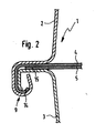
- FIG 2 is in detail the embodiment of the proposedsfalzes 9, wherein only the edge 14 of the one visible Inner half-shell 4 directly in the single-stage circumferential fold 9 bent while the non-angled Edge 15 of the other inner half-shell 5 is clamped in the circumferential fold 9 is.
Landscapes
- Engineering & Computer Science (AREA)
- Chemical & Material Sciences (AREA)
- Combustion & Propulsion (AREA)
- Mechanical Engineering (AREA)
- General Engineering & Computer Science (AREA)
- Exhaust Silencers (AREA)
Description
- Fig. 1
- einen Absorptions-/Reflexions-Schalldämpfer in einem schematischen Horizontalschnitt, und
- Fig. 2
- einen Vertikalschnitt des Schalldämpfers nach Fig. 1 im Bereich eines Umfangsfalzes.
Claims (2)
- Schalldämpfer (1), mit zwei Außenhalbschalen (2, 3) und zwei Innenhalbschalen (4, 5), in welchen eine Abgasführung (6) eingeprägt bzw. eingepresst ist, mit einem am Rand der Schalen (2, 3, 4, 5) verschweißten Abgaseintritt (7) und Abgasaustritt (8), und mit einem abgewinkelten Umfangsfalz (9), in dessen umgebogenen Teil die beiden Außenhalbschalen (2, 3) umgebogen sind,
dadurch gekennzeichnet, dass
nur der Rand (14) der einen Innenhalbschale (4) unmittelbar im einstufigen Umfangsfalz (9) gebogen aufgenommen und der Rand (15) der anderen Innenhalbschale (5) in dem Umfangsfalz (9) eingeklemmt ist, wobei im umgebogenen Teil des Umfangsfalzes (9) die beiden Außenhalbschalen (2, 3) und der Rand (14) der einen Innenhalbschale (4) umgebogen sind. - Schalldämpfer nach Anspruch 1, mit oberer Außenhalbschale (2) und unterer Außenhalbschale (3), sowie oberer Innenhalbschalen (4) und unterer Innenhalbschalen (5),
dadurch gekennzeichnet, dass
der Umfangsfalz (9) nach unten abgewinkelt ist.
Applications Claiming Priority (3)
| Application Number | Priority Date | Filing Date | Title |
|---|---|---|---|
| DE19627299A DE19627299A1 (de) | 1996-07-06 | 1996-07-06 | Schalldämpfer mit Außen- und Innenhalbschalen |
| DE19627299 | 1996-07-06 | ||
| EP97111003A EP0816650B1 (de) | 1996-07-06 | 1997-07-02 | Schalldämpfer mit Aussen- und Innenhalbschalen |
Related Parent Applications (1)
| Application Number | Title | Priority Date | Filing Date |
|---|---|---|---|
| EP97111003A Division EP0816650B1 (de) | 1996-07-06 | 1997-07-02 | Schalldämpfer mit Aussen- und Innenhalbschalen |
Publications (3)
| Publication Number | Publication Date |
|---|---|
| EP1101912A2 EP1101912A2 (de) | 2001-05-23 |
| EP1101912A3 EP1101912A3 (de) | 2003-11-19 |
| EP1101912B1 true EP1101912B1 (de) | 2005-08-31 |
Family
ID=7799127
Family Applications (2)
| Application Number | Title | Priority Date | Filing Date |
|---|---|---|---|
| EP97111003A Expired - Lifetime EP0816650B1 (de) | 1996-07-06 | 1997-07-02 | Schalldämpfer mit Aussen- und Innenhalbschalen |
| EP01103995A Expired - Lifetime EP1101912B1 (de) | 1996-07-06 | 1997-07-02 | Schalldämpfer mit Aussen- und Innenhalbschalen |
Family Applications Before (1)
| Application Number | Title | Priority Date | Filing Date |
|---|---|---|---|
| EP97111003A Expired - Lifetime EP0816650B1 (de) | 1996-07-06 | 1997-07-02 | Schalldämpfer mit Aussen- und Innenhalbschalen |
Country Status (2)
| Country | Link |
|---|---|
| EP (2) | EP0816650B1 (de) |
| DE (3) | DE19627299A1 (de) |
Cited By (1)
| Publication number | Priority date | Publication date | Assignee | Title |
|---|---|---|---|---|
| CN106041426B (zh) * | 2016-06-27 | 2018-07-03 | 常州旷达威德机械有限公司 | 一种锥体封头的加工方法 |
Families Citing this family (2)
| Publication number | Priority date | Publication date | Assignee | Title |
|---|---|---|---|---|
| EP1146206B1 (de) * | 2000-04-14 | 2006-08-02 | J. Eberspächer GmbH & Co. KG | Abgas-Schalldämpfer in Mehrkammerbauweise |
| DE10034538A1 (de) * | 2000-07-15 | 2002-01-24 | Eberspaecher J Gmbh & Co | Abgaskrümmer |
Family Cites Families (9)
| Publication number | Priority date | Publication date | Assignee | Title |
|---|---|---|---|---|
| GB1012463A (en) | 1963-04-11 | 1965-12-08 | Ford Motor Co | Motor vehicle exhaust muffler |
| US4014545A (en) | 1976-02-06 | 1977-03-29 | Keim Roy L | Ring toss game |
| DE8019067U1 (de) * | 1980-07-16 | 1980-10-30 | Paul Gillet Gmbh, 6732 Edenkoben | Schalldaempfer fuer kraftfahrzeuge |
| US4700806A (en) | 1986-11-25 | 1987-10-20 | Ap Industries, Inc. | Stamp formed muffler |
| US4941545A (en) * | 1989-04-28 | 1990-07-17 | Arvin Industries, Inc. | Muffler assembly |
| DE9308419U1 (de) * | 1993-06-05 | 1994-10-13 | Roth-Technik GmbH, 76571 Gaggenau | Schalldämpfer für vorzugsweise gasförmige Medien |
| DE9400796U1 (de) | 1994-01-20 | 1994-04-07 | Heinrich Gillet Gmbh & Co Kg, 67480 Edenkoben | Schalldämpfer |
| JPH07293234A (ja) * | 1994-04-25 | 1995-11-07 | Calsonic Corp | 消音器の支持構造 |
| DE4427459A1 (de) * | 1994-08-03 | 1996-02-08 | Roth Technik Gmbh | Abgasanlage |
-
1996
- 1996-07-06 DE DE19627299A patent/DE19627299A1/de not_active Withdrawn
-
1997
- 1997-07-02 DE DE59712413T patent/DE59712413D1/de not_active Expired - Lifetime
- 1997-07-02 DE DE59705625T patent/DE59705625D1/de not_active Expired - Lifetime
- 1997-07-02 EP EP97111003A patent/EP0816650B1/de not_active Expired - Lifetime
- 1997-07-02 EP EP01103995A patent/EP1101912B1/de not_active Expired - Lifetime
Cited By (1)
| Publication number | Priority date | Publication date | Assignee | Title |
|---|---|---|---|---|
| CN106041426B (zh) * | 2016-06-27 | 2018-07-03 | 常州旷达威德机械有限公司 | 一种锥体封头的加工方法 |
Also Published As
| Publication number | Publication date |
|---|---|
| EP0816650A1 (de) | 1998-01-07 |
| EP1101912A2 (de) | 2001-05-23 |
| DE59712413D1 (de) | 2005-10-06 |
| DE19627299A1 (de) | 1998-01-08 |
| EP0816650B1 (de) | 2001-12-05 |
| EP1101912A3 (de) | 2003-11-19 |
| DE59705625D1 (de) | 2002-01-17 |
Similar Documents
| Publication | Publication Date | Title |
|---|---|---|
| DE2738600C2 (de) | ||
| EP1146206B1 (de) | Abgas-Schalldämpfer in Mehrkammerbauweise | |
| DE69213709T2 (de) | Durch Stanzen hergestellter Schalldämpfer mit Reihenexpansionskammer und gebogen geformten Effektifströmungsröhren | |
| DE68906099T2 (de) | Durch stanzverfahren hergestellter schalldaempfer und katalytische konvertereinheit. | |
| DE3783872T2 (de) | Durch stanzverfahren hergestellter schalldaempfer. | |
| DE69510767T2 (de) | Durch Stanzverfahren hergestellter Schalldämpfer mit verschachtelten Kammern | |
| DE60025313T2 (de) | Doppelquerstromschalldämpfer | |
| DE2357992C2 (de) | Lötloser Wärmetauscher | |
| EP3473823B1 (de) | Schalldämpfer mit schalldämpfereinsatz und verfahren zur herstellung eines schalldämpfer mit schalldämpfereinsatz | |
| EP0664380A1 (de) | Schalldämpfer | |
| DE2913731C2 (de) | Katalytische Abgasreinigungsvorrichtung für den Verbrennungsmotor eines Kraftfahrzeugs | |
| DE69415796T2 (de) | Dreiteilige, durch Stanzverfahren hergestellte Verbindung zum Erzielen gleichlanger Abgasleitungen | |
| EP0849445B1 (de) | Abgassammler und Verfahren zu seiner Herstellung | |
| DE69929784T2 (de) | Schalldämpfer | |
| DE29802099U1 (de) | Abgasschalldämpfer für einen Zweitaktmotor | |
| EP0816648B1 (de) | Schalldämpfer für Kraftfahrzeuge | |
| DE69200194T2 (de) | Ansauggeräuschdämpfer. | |
| EP1101912A2 (de) | Schalldämpfer mit Aussen- und Innenhalbschalen | |
| DE19849118B4 (de) | Abgasschalldämpfer | |
| DE8812595U1 (de) | Brenner, insbesondere Gasbrenner | |
| DE112008001511T5 (de) | Schalldämpfer für eine Auspuffleitung eines Kraftfahrzeugs | |
| DE19636662B4 (de) | Abgaskatalysator für Verbrennungsmotoren | |
| DE102008017625B4 (de) | Teilstück für eine Abgasanlage eines Verbrennungsmotors und Verfahren zu seiner Herstellung | |
| DE3013692A1 (de) | Katalytischer konverter fuer brennkraftmaschinenabgase | |
| DE3631356A1 (de) | Verfahren zur herstellung von gehaeusen |
Legal Events
| Date | Code | Title | Description |
|---|---|---|---|
| PUAI | Public reference made under article 153(3) epc to a published international application that has entered the european phase |
Free format text: ORIGINAL CODE: 0009012 |
|
| AC | Divisional application: reference to earlier application |
Ref document number: 816650 Country of ref document: EP |
|
| AK | Designated contracting states |
Kind code of ref document: A2 Designated state(s): DE FR GB IT |
|
| PUAL | Search report despatched |
Free format text: ORIGINAL CODE: 0009013 |
|
| AK | Designated contracting states |
Kind code of ref document: A3 Designated state(s): DE FR GB IT |
|
| 17P | Request for examination filed |
Effective date: 20040519 |
|
| 17Q | First examination report despatched |
Effective date: 20040614 |
|
| AKX | Designation fees paid |
Designated state(s): DE FR GB IT |
|
| GRAP | Despatch of communication of intention to grant a patent |
Free format text: ORIGINAL CODE: EPIDOSNIGR1 |
|
| GRAS | Grant fee paid |
Free format text: ORIGINAL CODE: EPIDOSNIGR3 |
|
| GRAA | (expected) grant |
Free format text: ORIGINAL CODE: 0009210 |
|
| AC | Divisional application: reference to earlier application |
Ref document number: 0816650 Country of ref document: EP Kind code of ref document: P |
|
| AK | Designated contracting states |
Kind code of ref document: B1 Designated state(s): DE FR GB IT |
|
| REG | Reference to a national code |
Ref country code: GB Ref legal event code: FG4D Free format text: NOT ENGLISH |
|
| REF | Corresponds to: |
Ref document number: 59712413 Country of ref document: DE Date of ref document: 20051006 Kind code of ref document: P |
|
| GBT | Gb: translation of ep patent filed (gb section 77(6)(a)/1977) |
Effective date: 20051005 |
|
| ET | Fr: translation filed | ||
| PLBE | No opposition filed within time limit |
Free format text: ORIGINAL CODE: 0009261 |
|
| STAA | Information on the status of an ep patent application or granted ep patent |
Free format text: STATUS: NO OPPOSITION FILED WITHIN TIME LIMIT |
|
| 26N | No opposition filed |
Effective date: 20060601 |
|
| PGFP | Annual fee paid to national office [announced via postgrant information from national office to epo] |
Ref country code: DE Payment date: 20110731 Year of fee payment: 15 |
|
| PGFP | Annual fee paid to national office [announced via postgrant information from national office to epo] |
Ref country code: GB Payment date: 20120723 Year of fee payment: 16 |
|
| PGFP | Annual fee paid to national office [announced via postgrant information from national office to epo] |
Ref country code: IT Payment date: 20120724 Year of fee payment: 16 Ref country code: FR Payment date: 20120803 Year of fee payment: 16 |
|
| PG25 | Lapsed in a contracting state [announced via postgrant information from national office to epo] |
Ref country code: DE Free format text: LAPSE BECAUSE OF NON-PAYMENT OF DUE FEES Effective date: 20130201 |
|
| REG | Reference to a national code |
Ref country code: DE Ref legal event code: R119 Ref document number: 59712413 Country of ref document: DE Effective date: 20130201 |
|
| GBPC | Gb: european patent ceased through non-payment of renewal fee |
Effective date: 20130702 |
|
| REG | Reference to a national code |
Ref country code: FR Ref legal event code: ST Effective date: 20140331 |
|
| PG25 | Lapsed in a contracting state [announced via postgrant information from national office to epo] |
Ref country code: GB Free format text: LAPSE BECAUSE OF NON-PAYMENT OF DUE FEES Effective date: 20130702 |
|
| PG25 | Lapsed in a contracting state [announced via postgrant information from national office to epo] |
Ref country code: IT Free format text: LAPSE BECAUSE OF NON-PAYMENT OF DUE FEES Effective date: 20130702 Ref country code: FR Free format text: LAPSE BECAUSE OF NON-PAYMENT OF DUE FEES Effective date: 20130731 |