EP1101601A1 - Anlage zur Herstellung einer Wellpappebahn - Google Patents
Anlage zur Herstellung einer Wellpappebahn Download PDFInfo
- Publication number
- EP1101601A1 EP1101601A1 EP00124858A EP00124858A EP1101601A1 EP 1101601 A1 EP1101601 A1 EP 1101601A1 EP 00124858 A EP00124858 A EP 00124858A EP 00124858 A EP00124858 A EP 00124858A EP 1101601 A1 EP1101601 A1 EP 1101601A1
- Authority
- EP
- European Patent Office
- Prior art keywords
- corrugated cardboard
- sensor
- web
- designed
- distance
- Prior art date
- Legal status (The legal status is an assumption and is not a legal conclusion. Google has not performed a legal analysis and makes no representation as to the accuracy of the status listed.)
- Granted
Links
- 238000004519 manufacturing process Methods 0.000 title description 6
- 238000011156 evaluation Methods 0.000 claims description 8
- 238000003384 imaging method Methods 0.000 claims description 5
- 239000000123 paper Substances 0.000 claims description 4
- 238000001514 detection method Methods 0.000 description 6
- 238000002372 labelling Methods 0.000 description 1
- 230000007257 malfunction Effects 0.000 description 1
- 238000009966 trimming Methods 0.000 description 1
- 238000011144 upstream manufacturing Methods 0.000 description 1
Images

Classifications
-
- B—PERFORMING OPERATIONS; TRANSPORTING
- B31—MAKING ARTICLES OF PAPER, CARDBOARD OR MATERIAL WORKED IN A MANNER ANALOGOUS TO PAPER; WORKING PAPER, CARDBOARD OR MATERIAL WORKED IN A MANNER ANALOGOUS TO PAPER
- B31F—MECHANICAL WORKING OR DEFORMATION OF PAPER, CARDBOARD OR MATERIAL WORKED IN A MANNER ANALOGOUS TO PAPER
- B31F1/00—Mechanical deformation without removing material, e.g. in combination with laminating
- B31F1/20—Corrugating; Corrugating combined with laminating to other layers
- B31F1/24—Making webs in which the channel of each corrugation is transverse to the web feed
- B31F1/26—Making webs in which the channel of each corrugation is transverse to the web feed by interengaging toothed cylinders cylinder constructions
- B31F1/28—Making webs in which the channel of each corrugation is transverse to the web feed by interengaging toothed cylinders cylinder constructions combined with uniting the corrugated webs to flat webs ; Making double-faced corrugated cardboard
- B31F1/2831—Control
Definitions
- the invention relates to a device according to the preamble of the claim 1.
- Plants for the production of corrugated cardboard webs, in particular for Production of corrugated cardboard sheets laminated on one side, that is, from a corrugated Paper web and a cover web are generally known for example from EP 0 687 552 A (corresponding to US Pat. No. 5,632,850) or DE 195 36 007 A (corresponding to GB 2,305,675 A).
- EP 0 687 552 A corresponding to US Pat. No. 5,632,850
- DE 195 36 007 A corresponding to GB 2,305,675 A.
- With such Machines can be caused by many possible malfunctions, that the quality of the corrugated cardboard does not meet the target specifications that for example the format accuracy of a corrugated cardboard web, i.e. the location their longitudinal edges and / or the location of a crease and / or the location of a Longitudinal cut are not correct.
- the invention has for its object a device of the generic type To create a type that captures the accuracy of the format Corrugated cardboard enables.
- Claims 2 to 6 represent configurations of sensors by means of one or more quality-determining features of the corrugated cardboard web be recorded.
- Claims 7 and 8 give possible further refinements the device again.
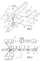
- a corrugated cardboard web 1 is shown schematically, the one upper first cover sheet 2 and a lower second cover sheet 3, each made Paper, and one arranged between the cover sheets 2, 3 and with these has glued corrugated paper web 4.
- the corrugated cardboard web 1 is located in the course of their manufacture on a plant for the production of corrugated cardboard, namely in the transport direction 5 behind a creasing and slitting device, as for example in EP 0 692 369 B1 (corresponding US Pat. No. 5,857,395) is shown and described, whereupon expressly is referred.
- the upper cover sheet 2 is in Transport direction 5 extending upper grooves 6 and the lower cover sheet 3 with the lower grooves 7a assigned to the upper grooves 6a, 6b, 7b has been provided. Furthermore, the corrugated cardboard web 1 is in this device provided with a longitudinal section 8 extending in the transport direction 5 through which the corrugated cardboard web 1 in two sub-webs 1a, 1b with the width c or d has been divided.
- corrugated cardboard web 1 divided a first quality detection device 9, which has two laser sensors 10, 11, the above and are arranged below the corrugated cardboard web 1. They are transverse to the direction of transport 5 and across the corrugated cardboard 1 on guides 12, 13 by means of not shown drives can be moved synchronously, which is indicated by the double arrows 14 is indicated in Fig. 1.
- the laser sensor 10 detects the distance a to upper cover sheet 2; the lower laser sensor 11 detects the distance b to lower cover sheet 3.
- the sensors 10 are displaced transversely, 11 these over the upper groove 6a or 6b or the lower groove 7a or 7b drive, then they record the change in distance a or b, record thus the position of the grooves 6a, 6b or 7a, 7b transverse to the transport direction 5. In the same way, they detect the position of the longitudinal section 8 and the position the side edges 25, 26. By detecting the grooves 6a, 6b, 7a, 7b and the longitudinal section 8 and the side edges 25, 26 is determined in each case whether their position in relation to each other is correct.
- the values of the distances a and b determined by the laser sensors 10, 11 are fed to an evaluation device 15. There the distance of the Side edge 25 of the partial web la from the longitudinal section 8, ie the width c of sub-web 1a. In the same way, the distance of the longitudinal section 8 from the side edge 26 of the partial web 1b, that is to say its width d, determined. Furthermore, the distance e of the grooves 6a, 7a from the side edge 25 and / or the distance f of the creasing 6a, 7a of the partial web la from Longitudinal section 8 determined.
- the evaluation device 15, a display device 15a can be assigned.
- the evaluation the position information can then be subordinate to the evaluation device 15
- the control device 16 controlled an electric motor 17, which is, for example the drive motor one downstream in the system in the transport direction 5 Cross cutter can act, by means of which a web section is cut out that is recognized as improper. Such a the section cut out is placed in a downstream of the cross cutter Soft excreted.
- 3 and 4 is a second quality detection device 18 shown, in the same way as in the first quality recording facility 9 - the correct lateral position of an upper groove 6a, 6b and one lower creasing 7a, 7b and a longitudinal section 8 is detected.
- a so-called 3D scanner is provided as sensor 19.
- This 3D scanner has one or more light sources 20, which are arranged at a cross to the Transport direction 5 above the upper cover sheet 2 arranged carrier 21 are attached.
- the light sources upstream or downstream - a line imaging system 22 in the form of a Scanners provided.
- a gap-forming device in the form of two Rollers 23, 24 are provided, against the upper and the lower cover web 2, 3 abut, the upper roller 23 forming an aperture.
- Fig. 4 are for the passage of light from the light sources 20 to the line-imaging system 22 only the upper groove 6a, 6b and the longitudinal section 8 free. Their position transverse to the direction of transport 5 can be captured exactly.
- the distance f between the Creasing 6a, 7a of the partial web la and the longitudinal section 8 or the distance g of the longitudinal section 8 determined from the scoring 6b, 7b of the partial web 1b.
- the evaluation and the possible intervention in the system takes place in the same way
- the same way as for the first quality recording device 9 Way as the location of the upper grooves 6a, 6b and the middle longitudinal section 8 the position of the outer side edges 25, 26 can be detected, which are generated, for example, by side trimming.
Landscapes
- Engineering & Computer Science (AREA)
- Mechanical Engineering (AREA)
- Making Paper Articles (AREA)
- Paper (AREA)
- Machines For Manufacturing Corrugated Board In Mechanical Paper-Making Processes (AREA)
- Laminated Bodies (AREA)
- Length Measuring Devices By Optical Means (AREA)
Abstract
Description
- Fig. 1
- eine erste Ausführungsform einer Qualitäts-Erfassungs-Vorrichtung in einer perspektivischen schematischen Darstellung,
- Fig. 2
- die erste Ausführungsform einer Qualitäts-Erfassungs-Vorrichtung in einer Querschnittsdarstellung,
- Fig. 3
- eine zweite Ausführungsform einer Qualitäts-Erfassungs-Vorrichtung in einer perspektivischen schematischen Ansicht und
- Fig. 4
- einen Querschnitt durch die zweite Ausführungsform einer . Qualitäts-Erfassungs- Vorrichtung.
Claims (8)
- Vorrichtung zur Erfassung der Formatgenauigkeit einer in einer Transportrichtung (5) bewegten Wellpappebahn (1)dadurch gekennzeichnet,mit einer ersten und einer zweiten glatten Deckbahn (2, 3),mit mindestens einer zwischen den Deckbahnen (2, 3) angeordneten gewellten Papierbahn (4),mit mehreren in Transportrichtung (5) verlaufenden Profilierungen, nämlichSeitenkanten (25, 26); und gegebenenfallsmindestens einen, die Wellpappebahn (1) in Teil-Bahnen (1a, 1b) teilenden Längsschnitt (8) und/odermindestens eine Rillung (6a, 7a; 6b, 7b),
daß mindestens ein Sensor (10, 11; 19) zur Erfassung der Lage von mindestens zwei Profilierungen relativ zueinander vorgesehen ist, dem ein Auswerte-Gerät (15) zur Ermittlung des Abstandes (c, d; e, f; g, h) der mindestens zwei Profilierungen voneinander nachgeschaltet ist. - Vorrichtung nach Anspruch 1, dadurch gekennzeichnet,
daß der mindestens eine Sensor (10, 11; 19) berührungslos arbeitend ausgebildet ist. - Vorrichtung nach Anspruch 2, dadurch gekennzeichnet,daß beiderseits der Wellpappebahn (1) zwei Sensoren (10, 11) angeordnet sind,von denen ein erster Sensor (10) den Abstand a der ersten Deckbahn (2) vom ersten Sensor (10) messend ausgebildet ist undvon denen ein zweiter Sensor (11) den Abstand b der zweiten Deckbahn (3) vom zweiten Sensor (11) messend ausgebildet ist.
- Vorrichtung nach Anspruch 3, dadurch gekennzeichnet,
daß die Sensoren als Laser-Sensoren (10, 11) ausgebildet sind. - Vorrichtung nach Anspruch 3, dadurch gekennzeichnet, daß die Sensoren (10, 11) synchron zueinander quer zur Transportrichtung (5) der Wellpappebahn (1) verschiebbar ausgebildet sind.
- Vorrichtung nach Anspruch 1, dadurch gekennzeichnet,daß auf derselben Seite der Wellpappebahn (1) mindestens eine Lichtquelle (20) und ein das Licht aufnehmendes, zeilenabbildendes System (22) vorgesehen sind, unddaß zwischen der mindestens einen Lichtquelle (20) und dem zeilenabbildenden System (22) eine an der Wellpappebahn (1) anliegende, lediglich die Rillung (6a, 6b) und/oder den Längsschnitt (8) und/oder die Seitenkanten (25, 26) freilassende Blende (23) vorgesehen ist.
- Vorrichtung nach Anspruch 1, dadurch gekennzeichnet, daß dem Auswerte-Gerät (15) ein Anzeige-Gerät (15a) zugeordnet ist.
- Vorrichtung nach Anspruch 1, dadurch gekennzeichnet, daß dem Auswerte-Gerät (15) ein Steuer-Gerät (16) nachgeordnet ist.
Applications Claiming Priority (2)
| Application Number | Priority Date | Filing Date | Title |
|---|---|---|---|
| DE19955916 | 1999-11-20 | ||
| DE19955916A DE19955916A1 (de) | 1999-11-20 | 1999-11-20 | Anlage zur Herstellung einer Wellpappebahn |
Publications (2)
| Publication Number | Publication Date |
|---|---|
| EP1101601A1 true EP1101601A1 (de) | 2001-05-23 |
| EP1101601B1 EP1101601B1 (de) | 2005-01-26 |
Family
ID=7929766
Family Applications (1)
| Application Number | Title | Priority Date | Filing Date |
|---|---|---|---|
| EP00124858A Expired - Lifetime EP1101601B1 (de) | 1999-11-20 | 2000-11-15 | Anlage zur Herstellung einer Wellpappebahn |
Country Status (4)
| Country | Link |
|---|---|
| EP (1) | EP1101601B1 (de) |
| AT (1) | ATE287791T1 (de) |
| DE (2) | DE19955916A1 (de) |
| ES (1) | ES2235740T3 (de) |
Cited By (2)
| Publication number | Priority date | Publication date | Assignee | Title |
|---|---|---|---|---|
| EP2048494A1 (de) * | 2007-10-09 | 2009-04-15 | BHS Corrugated Maschinen-und Anlagenbau GmbH | Vorrichtung zur Erfassung der Formatgenauigkeit einer Wellpappebahn |
| WO2016156199A1 (de) * | 2015-04-02 | 2016-10-06 | Bhs Corrugated Maschinen- Und Anlagenbau Gmbh | Vorrichtung zur bestimmung der qualität einer wellpappe-bahn |
Families Citing this family (4)
| Publication number | Priority date | Publication date | Assignee | Title |
|---|---|---|---|---|
| DE102007022580B4 (de) * | 2007-05-11 | 2011-07-28 | Electronic Wood Systems GmbH, 31785 | Verfahren und Vorrichtung zur Dickenmessung einer Platte |
| DE102015000191A1 (de) * | 2015-01-03 | 2016-07-21 | RSD - Industrietechnik GmbH | Verklebungs Kontrolle |
| DE102019117193B4 (de) * | 2019-06-26 | 2023-06-07 | Baumer Electric Ag | Sensorvorrichtung zur Bestimmung einer Wegstrecke, einer Fläche oder eines Volumens |
| DE102024203709A1 (de) * | 2024-04-22 | 2025-10-23 | Bhs Corrugated Maschinen- Und Anlagenbau Gmbh | Verfahren zur Identifizierung von Anomalien und somit auch tatsächlichen Bearbeitungspositionen einer Bahn sowie zur Klassifizierung dieser Anomalien, Anlage und Computerprogrammprodukt |
Citations (6)
| Publication number | Priority date | Publication date | Assignee | Title |
|---|---|---|---|---|
| EP0162139A2 (de) * | 1984-05-25 | 1985-11-27 | Werner H. K. Peters Maschinenfabrik GmbH | Vorrichtung zur Erfassung und/oder Steuerung der Kantenlage von Papierbahnen in Wellpappenmaschinen oder dergleichen |
| US4737846A (en) * | 1986-05-29 | 1988-04-12 | Rengo Co., Ltd. | Device for detecting defects in single faced corrugated fiberboards |
| GB2305675A (en) * | 1995-09-28 | 1997-04-16 | Bhs Corr Masch & Anlagenbau | Corrugating board: web pressing |
| US5632850A (en) * | 1994-06-16 | 1997-05-27 | BHS Corrugated Maschinen- und Anlagenbau GmbH | Machine for the manufacture of a web of at least single-face corrugated board |
| US5857395A (en) * | 1994-07-16 | 1999-01-12 | Bhs Corrugated Maschinen- Und Anlagenbau Gmbh | Apparatus for the manufacture of sheets of corrugated board of variable size |
| DE19802913A1 (de) * | 1998-01-27 | 1999-07-29 | Bhs Corr Masch & Anlagenbau | Vorrichtung zur Erfassung der Kantenlage einer bewegten Materialbahn |
Family Cites Families (2)
| Publication number | Priority date | Publication date | Assignee | Title |
|---|---|---|---|---|
| JPS5689541A (en) * | 1979-12-05 | 1981-07-20 | Rengo Co Ltd | Method and device for guiding one side corrugated cardboard |
| US5581353A (en) * | 1995-02-14 | 1996-12-03 | Qualitek Ltd. | Laser-based measurement apparatus and method for the on-line measurement of multiple corrugated board characteristics |
-
1999
- 1999-11-20 DE DE19955916A patent/DE19955916A1/de not_active Withdrawn
-
2000
- 2000-11-15 AT AT00124858T patent/ATE287791T1/de not_active IP Right Cessation
- 2000-11-15 ES ES00124858T patent/ES2235740T3/es not_active Expired - Lifetime
- 2000-11-15 EP EP00124858A patent/EP1101601B1/de not_active Expired - Lifetime
- 2000-11-15 DE DE50009341T patent/DE50009341D1/de not_active Expired - Lifetime
Patent Citations (6)
| Publication number | Priority date | Publication date | Assignee | Title |
|---|---|---|---|---|
| EP0162139A2 (de) * | 1984-05-25 | 1985-11-27 | Werner H. K. Peters Maschinenfabrik GmbH | Vorrichtung zur Erfassung und/oder Steuerung der Kantenlage von Papierbahnen in Wellpappenmaschinen oder dergleichen |
| US4737846A (en) * | 1986-05-29 | 1988-04-12 | Rengo Co., Ltd. | Device for detecting defects in single faced corrugated fiberboards |
| US5632850A (en) * | 1994-06-16 | 1997-05-27 | BHS Corrugated Maschinen- und Anlagenbau GmbH | Machine for the manufacture of a web of at least single-face corrugated board |
| US5857395A (en) * | 1994-07-16 | 1999-01-12 | Bhs Corrugated Maschinen- Und Anlagenbau Gmbh | Apparatus for the manufacture of sheets of corrugated board of variable size |
| GB2305675A (en) * | 1995-09-28 | 1997-04-16 | Bhs Corr Masch & Anlagenbau | Corrugating board: web pressing |
| DE19802913A1 (de) * | 1998-01-27 | 1999-07-29 | Bhs Corr Masch & Anlagenbau | Vorrichtung zur Erfassung der Kantenlage einer bewegten Materialbahn |
Cited By (4)
| Publication number | Priority date | Publication date | Assignee | Title |
|---|---|---|---|---|
| EP2048494A1 (de) * | 2007-10-09 | 2009-04-15 | BHS Corrugated Maschinen-und Anlagenbau GmbH | Vorrichtung zur Erfassung der Formatgenauigkeit einer Wellpappebahn |
| US7952714B2 (en) | 2007-10-09 | 2011-05-31 | BHS Corrugated Machinen-und Anlagenbau | Apparatus for detection of the accuracy of format of a web of corrugated cardboard |
| WO2016156199A1 (de) * | 2015-04-02 | 2016-10-06 | Bhs Corrugated Maschinen- Und Anlagenbau Gmbh | Vorrichtung zur bestimmung der qualität einer wellpappe-bahn |
| US10655950B2 (en) | 2015-04-02 | 2020-05-19 | Bhs Corrugated Maschinen- Und Anlagenbau Gmbh | Device for determining the quality of a corrugated board web |
Also Published As
| Publication number | Publication date |
|---|---|
| EP1101601B1 (de) | 2005-01-26 |
| DE50009341D1 (de) | 2005-03-03 |
| ATE287791T1 (de) | 2005-02-15 |
| ES2235740T3 (es) | 2005-07-16 |
| DE19955916A1 (de) | 2001-05-23 |
Similar Documents
| Publication | Publication Date | Title |
|---|---|---|
| EP0091714B1 (de) | Verfahren und Vorrichtung zur Herstellung druckfrischer, numerierter und auf Format geschnittener Wertscheine | |
| EP1270473A2 (de) | Schräglauf-Kompensations-Vorrichtung für Wellpappeanlage | |
| DE69100928T2 (de) | Rotierende Schneidevorrichtung. | |
| DE69218621T2 (de) | Endlosformular und vorrichtung zum herstellen von briefbogen davon | |
| DE10312600A1 (de) | Wellpappe-Anlage sowie Verfahren zur Herstellung von Wellpappe-Bögen | |
| EP3354426B1 (de) | Positionskorrektur beim passmarken-schnitt von wellpappe | |
| EP0692369A1 (de) | Anlage zur Herstellung von Wellpappebögen mit veränderbarem Format | |
| DE2660035C2 (de) | Vorrichtung zum Abstreifen von gestanzten Abschnitten oder Ausschnitten aus Wellpappe- oder Kartonzuschnitten | |
| EP1166977B1 (de) | Schneidmaschine zum selbsttätigen Beschneiden von Druckerzeugnissen | |
| EP2060388A2 (de) | Wellpappe-Anlage und Verfahren zur Herstellung einer endlosen Wellpappe-Bahn | |
| DE69905123T2 (de) | Verfahren zum Wechseln zwischen Bestellungen für eine Wellpappenmaschine | |
| EP1105333B1 (de) | Verfahren und vorrichtung zur perforation von materialbahnen | |
| DE69118667T2 (de) | Verfahren und Vorrichtung zum Anbringen von Verbindungsstellen-Anzeigelöchern in Fotopapier | |
| EP0523346A1 (de) | Vorrichtung zum Transport einer Papierbahn in den Falzapparat einer Druckerpresse | |
| EP1101601B1 (de) | Anlage zur Herstellung einer Wellpappebahn | |
| EP0203328A2 (de) | Einrichtung zum Verschieben von Untermessern | |
| EP0755356B1 (de) | Vorrichtung und verfahren zum zusammenführen und veredeln mehrerer papierbahnen | |
| EP0622320A1 (de) | Verarbeitungsvorrichtung und Verfahren zur Bearbeitung von Material zu Blattlagen | |
| DE69813747T2 (de) | Einrichtung zum Zuführen von Schachtelzuschnitten und Verfahren | |
| EP1025993B1 (de) | Vorrichtung zum Auftragen einer Längsleimung in einer Falzvorrichtung von schnellaufenden Rotationsdruckmaschinen | |
| EP1112952B1 (de) | Vorrichtung zum fortlaufenden Falzen von flachem Material | |
| EP3077306B1 (de) | Vorrichtung sowie verfahren zum schneiden eines bahnmaterials in teilbahnen und spreizen der teilbahnen | |
| DE3633168A1 (de) | Vorrichtung zum gleichmaessigen vorziehen der einzelnen lagen einer mehrlagigen bahn aus papier oder dergl. | |
| DE102022207528A1 (de) | Gegenzylinder-Anordnung | |
| EP1101600A1 (de) | Anlage zur Herstellung einer Wellpappebahn |
Legal Events
| Date | Code | Title | Description |
|---|---|---|---|
| PUAI | Public reference made under article 153(3) epc to a published international application that has entered the european phase |
Free format text: ORIGINAL CODE: 0009012 |
|
| AK | Designated contracting states |
Kind code of ref document: A1 Designated state(s): AT BE CH CY DE DK ES FI FR GB GR IE IT LI LU MC NL PT SE TR |
|
| AX | Request for extension of the european patent |
Free format text: AL;LT;LV;MK;RO;SI |
|
| TPAD | Observations filed by third parties |
Free format text: ORIGINAL CODE: EPIDOS TIPA |
|
| 17P | Request for examination filed |
Effective date: 20011015 |
|
| AKX | Designation fees paid |
Free format text: AT BE CH CY DE DK ES FI FR GB GR IE IT LI LU MC NL PT SE TR |
|
| 17Q | First examination report despatched |
Effective date: 20030227 |
|
| GRAP | Despatch of communication of intention to grant a patent |
Free format text: ORIGINAL CODE: EPIDOSNIGR1 |
|
| GRAS | Grant fee paid |
Free format text: ORIGINAL CODE: EPIDOSNIGR3 |
|
| GRAA | (expected) grant |
Free format text: ORIGINAL CODE: 0009210 |
|
| AK | Designated contracting states |
Kind code of ref document: B1 Designated state(s): AT BE CH CY DE DK ES FI FR GB GR IE IT LI LU MC NL PT SE TR |
|
| PG25 | Lapsed in a contracting state [announced via postgrant information from national office to epo] |
Ref country code: IE Free format text: LAPSE BECAUSE OF FAILURE TO SUBMIT A TRANSLATION OF THE DESCRIPTION OR TO PAY THE FEE WITHIN THE PRESCRIBED TIME-LIMIT Effective date: 20050126 Ref country code: TR Free format text: LAPSE BECAUSE OF FAILURE TO SUBMIT A TRANSLATION OF THE DESCRIPTION OR TO PAY THE FEE WITHIN THE PRESCRIBED TIME-LIMIT Effective date: 20050126 Ref country code: NL Free format text: LAPSE BECAUSE OF FAILURE TO SUBMIT A TRANSLATION OF THE DESCRIPTION OR TO PAY THE FEE WITHIN THE PRESCRIBED TIME-LIMIT Effective date: 20050126 Ref country code: FI Free format text: LAPSE BECAUSE OF FAILURE TO SUBMIT A TRANSLATION OF THE DESCRIPTION OR TO PAY THE FEE WITHIN THE PRESCRIBED TIME-LIMIT Effective date: 20050126 |
|
| REG | Reference to a national code |
Ref country code: GB Ref legal event code: FG4D Free format text: NOT ENGLISH |
|
| REG | Reference to a national code |
Ref country code: CH Ref legal event code: EP |
|
| GBT | Gb: translation of ep patent filed (gb section 77(6)(a)/1977) |
Effective date: 20050126 |
|
| REG | Reference to a national code |
Ref country code: IE Ref legal event code: FG4D Free format text: GERMAN |
|
| REF | Corresponds to: |
Ref document number: 50009341 Country of ref document: DE Date of ref document: 20050303 Kind code of ref document: P |
|
| RAP2 | Party data changed (patent owner data changed or rights of a patent transferred) |
Owner name: BHS CORRUGATED MASCHINEN-UND ANLAGENBAU GMBH |
|
| PG25 | Lapsed in a contracting state [announced via postgrant information from national office to epo] |
Ref country code: DK Free format text: LAPSE BECAUSE OF FAILURE TO SUBMIT A TRANSLATION OF THE DESCRIPTION OR TO PAY THE FEE WITHIN THE PRESCRIBED TIME-LIMIT Effective date: 20050426 Ref country code: GR Free format text: LAPSE BECAUSE OF FAILURE TO SUBMIT A TRANSLATION OF THE DESCRIPTION OR TO PAY THE FEE WITHIN THE PRESCRIBED TIME-LIMIT Effective date: 20050426 Ref country code: SE Free format text: LAPSE BECAUSE OF FAILURE TO SUBMIT A TRANSLATION OF THE DESCRIPTION OR TO PAY THE FEE WITHIN THE PRESCRIBED TIME-LIMIT Effective date: 20050426 |
|
| NLT2 | Nl: modifications (of names), taken from the european patent patent bulletin |
Owner name: BHS CORRUGATED MASCHINEN-UND ANLAGENBAU GMBH |
|
| NLV1 | Nl: lapsed or annulled due to failure to fulfill the requirements of art. 29p and 29m of the patents act | ||
| REG | Reference to a national code |
Ref country code: ES Ref legal event code: FG2A Ref document number: 2235740 Country of ref document: ES Kind code of ref document: T3 |
|
| REG | Reference to a national code |
Ref country code: IE Ref legal event code: FD4D |
|
| PG25 | Lapsed in a contracting state [announced via postgrant information from national office to epo] |
Ref country code: CY Free format text: LAPSE BECAUSE OF FAILURE TO SUBMIT A TRANSLATION OF THE DESCRIPTION OR TO PAY THE FEE WITHIN THE PRESCRIBED TIME-LIMIT Effective date: 20051115 Ref country code: AT Free format text: LAPSE BECAUSE OF NON-PAYMENT OF DUE FEES Effective date: 20051115 |
|
| PG25 | Lapsed in a contracting state [announced via postgrant information from national office to epo] |
Ref country code: MC Free format text: LAPSE BECAUSE OF NON-PAYMENT OF DUE FEES Effective date: 20051130 Ref country code: CH Free format text: LAPSE BECAUSE OF NON-PAYMENT OF DUE FEES Effective date: 20051130 Ref country code: LU Free format text: LAPSE BECAUSE OF NON-PAYMENT OF DUE FEES Effective date: 20051130 Ref country code: BE Free format text: LAPSE BECAUSE OF NON-PAYMENT OF DUE FEES Effective date: 20051130 Ref country code: LI Free format text: LAPSE BECAUSE OF NON-PAYMENT OF DUE FEES Effective date: 20051130 |
|
| PLBE | No opposition filed within time limit |
Free format text: ORIGINAL CODE: 0009261 |
|
| STAA | Information on the status of an ep patent application or granted ep patent |
Free format text: STATUS: NO OPPOSITION FILED WITHIN TIME LIMIT |
|
| ET | Fr: translation filed | ||
| 26N | No opposition filed |
Effective date: 20051027 |
|
| REG | Reference to a national code |
Ref country code: CH Ref legal event code: PL |
|
| BERE | Be: lapsed |
Owner name: BHS CORRUGATED MASCHINEN- UND ANLAGENBAU G.M.B.H. Effective date: 20051130 |
|
| PG25 | Lapsed in a contracting state [announced via postgrant information from national office to epo] |
Ref country code: PT Free format text: LAPSE BECAUSE OF NON-PAYMENT OF DUE FEES Effective date: 20050626 |
|
| REG | Reference to a national code |
Ref country code: FR Ref legal event code: PLFP Year of fee payment: 16 |
|
| REG | Reference to a national code |
Ref country code: FR Ref legal event code: PLFP Year of fee payment: 17 |
|
| PGFP | Annual fee paid to national office [announced via postgrant information from national office to epo] |
Ref country code: FR Payment date: 20161124 Year of fee payment: 17 |
|
| REG | Reference to a national code |
Ref country code: FR Ref legal event code: ST Effective date: 20180731 |
|
| PG25 | Lapsed in a contracting state [announced via postgrant information from national office to epo] |
Ref country code: FR Free format text: LAPSE BECAUSE OF NON-PAYMENT OF DUE FEES Effective date: 20171130 |
|
| PGFP | Annual fee paid to national office [announced via postgrant information from national office to epo] |
Ref country code: IT Payment date: 20191120 Year of fee payment: 20 Ref country code: ES Payment date: 20191216 Year of fee payment: 20 |
|
| PGFP | Annual fee paid to national office [announced via postgrant information from national office to epo] |
Ref country code: GB Payment date: 20191126 Year of fee payment: 20 Ref country code: DE Payment date: 20200124 Year of fee payment: 20 |
|
| REG | Reference to a national code |
Ref country code: DE Ref legal event code: R071 Ref document number: 50009341 Country of ref document: DE |
|
| REG | Reference to a national code |
Ref country code: GB Ref legal event code: PE20 Expiry date: 20201114 |
|
| PG25 | Lapsed in a contracting state [announced via postgrant information from national office to epo] |
Ref country code: GB Free format text: LAPSE BECAUSE OF EXPIRATION OF PROTECTION Effective date: 20201114 |
|
| REG | Reference to a national code |
Ref country code: ES Ref legal event code: FD2A Effective date: 20210226 |
|
| PG25 | Lapsed in a contracting state [announced via postgrant information from national office to epo] |
Ref country code: ES Free format text: LAPSE BECAUSE OF EXPIRATION OF PROTECTION Effective date: 20201116 |