EP1099865A2 - Zierleistenbefestigung, insbesondere für Kraftwagen - Google Patents
Zierleistenbefestigung, insbesondere für Kraftwagen Download PDFInfo
- Publication number
- EP1099865A2 EP1099865A2 EP00120063A EP00120063A EP1099865A2 EP 1099865 A2 EP1099865 A2 EP 1099865A2 EP 00120063 A EP00120063 A EP 00120063A EP 00120063 A EP00120063 A EP 00120063A EP 1099865 A2 EP1099865 A2 EP 1099865A2
- Authority
- EP
- European Patent Office
- Prior art keywords
- recess
- decorative strip
- expansion pin
- attachment according
- pin
- Prior art date
- Legal status (The legal status is an assumption and is not a legal conclusion. Google has not performed a legal analysis and makes no representation as to the accuracy of the status listed.)
- Granted
Links
Images
Classifications
-
- B—PERFORMING OPERATIONS; TRANSPORTING
- B60—VEHICLES IN GENERAL
- B60R—VEHICLES, VEHICLE FITTINGS, OR VEHICLE PARTS, NOT OTHERWISE PROVIDED FOR
- B60R13/00—Elements for body-finishing, identifying, or decorating; Arrangements or adaptations for advertising purposes
- B60R13/02—Internal Trim mouldings ; Internal Ledges; Wall liners for passenger compartments; Roof liners
- B60R13/0206—Arrangements of fasteners and clips specially adapted for attaching inner vehicle liners or mouldings
-
- B—PERFORMING OPERATIONS; TRANSPORTING
- B60—VEHICLES IN GENERAL
- B60R—VEHICLES, VEHICLE FITTINGS, OR VEHICLE PARTS, NOT OTHERWISE PROVIDED FOR
- B60R13/00—Elements for body-finishing, identifying, or decorating; Arrangements or adaptations for advertising purposes
- B60R13/04—External Ornamental or guard strips; Ornamental inscriptive devices thereon
-
- F—MECHANICAL ENGINEERING; LIGHTING; HEATING; WEAPONS; BLASTING
- F16—ENGINEERING ELEMENTS AND UNITS; GENERAL MEASURES FOR PRODUCING AND MAINTAINING EFFECTIVE FUNCTIONING OF MACHINES OR INSTALLATIONS; THERMAL INSULATION IN GENERAL
- F16B—DEVICES FOR FASTENING OR SECURING CONSTRUCTIONAL ELEMENTS OR MACHINE PARTS TOGETHER, e.g. NAILS, BOLTS, CIRCLIPS, CLAMPS, CLIPS OR WEDGES; JOINTS OR JOINTING
- F16B19/00—Bolts without screw-thread; Pins, including deformable elements; Rivets
- F16B19/04—Rivets; Spigots or the like fastened by riveting
- F16B19/08—Hollow rivets; Multi-part rivets
- F16B19/10—Hollow rivets; Multi-part rivets fastened by expanding mechanically
- F16B19/1027—Multi-part rivets
- F16B19/1036—Blind rivets
- F16B19/1081—Blind rivets fastened by a drive-pin
-
- F—MECHANICAL ENGINEERING; LIGHTING; HEATING; WEAPONS; BLASTING
- F16—ENGINEERING ELEMENTS AND UNITS; GENERAL MEASURES FOR PRODUCING AND MAINTAINING EFFECTIVE FUNCTIONING OF MACHINES OR INSTALLATIONS; THERMAL INSULATION IN GENERAL
- F16B—DEVICES FOR FASTENING OR SECURING CONSTRUCTIONAL ELEMENTS OR MACHINE PARTS TOGETHER, e.g. NAILS, BOLTS, CIRCLIPS, CLAMPS, CLIPS OR WEDGES; JOINTS OR JOINTING
- F16B5/00—Joining sheets or plates, e.g. panels, to one another or to strips or bars parallel to them
- F16B5/12—Fastening strips or bars to sheets or plates, e.g. rubber strips, decorative strips for motor vehicles, by means of clips
- F16B5/123—Auxiliary fasteners specially designed for this purpose
-
- F—MECHANICAL ENGINEERING; LIGHTING; HEATING; WEAPONS; BLASTING
- F16—ENGINEERING ELEMENTS AND UNITS; GENERAL MEASURES FOR PRODUCING AND MAINTAINING EFFECTIVE FUNCTIONING OF MACHINES OR INSTALLATIONS; THERMAL INSULATION IN GENERAL
- F16B—DEVICES FOR FASTENING OR SECURING CONSTRUCTIONAL ELEMENTS OR MACHINE PARTS TOGETHER, e.g. NAILS, BOLTS, CIRCLIPS, CLAMPS, CLIPS OR WEDGES; JOINTS OR JOINTING
- F16B5/00—Joining sheets or plates, e.g. panels, to one another or to strips or bars parallel to them
- F16B5/12—Fastening strips or bars to sheets or plates, e.g. rubber strips, decorative strips for motor vehicles, by means of clips
- F16B5/128—Fastening strips or bars to sheets or plates, e.g. rubber strips, decorative strips for motor vehicles, by means of clips a strip with a C-or U-shaped cross section being fastened to a plate such that the fastening means remain invisible, e.g. the fastening being completely enclosed by the strip
Definitions
- the invention relates to a molding attachment, in particular for Motor vehicle, according to the preamble of claim 1.
- a known trim strip attachment is an existing plastic Fastening clip by means of a slotted foot part in an opening in a sheet or The same can be used and there through a in a central bore of Fixing clip insertable expansion pin can be fixed.
- the fastening clip is included a support plate on the side of the plate facing away from the foot part and points in Distance from the support plate on a head piece, at least from the trim is partially encompassed.
- This trim attachment has the disadvantage that the expansion pin of Fastening clips are not reusable because it is removed when the Fastening clips can only be moved in the direction of insertion until it moves away from the Fastening clip releases and in the adjacent, mostly inaccessible Body cavity falls. There he can make undesirable noises while driving cause. When reusing the fastening clip, a new spreader pin must be in the central hole of the fastening clip can be used.
- the object of the invention is to attach a molding of the aforementioned To further develop the genus so that the complete fastening clip including the Spreader pin is reusable.
- the main advantages achieved with the invention are that the recess on the head piece and by at least one slot-like recess on Expansion pin disassembly of the expansion pin against the direction of insertion Spreader pin is made possible by means of an auxiliary tool, so that the complete Fastening clip is reusable. Unwanted noise when driving due to expansion pins lying around in inaccessible body cavities are thus avoided.
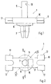
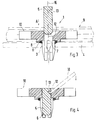
- the plastic fastening clip 1 shown in the drawing has a slotted foot part 2, which in an opening 3 of a sheet 4 or one Carrier part is inserted and there by driving in the indicated in Fig. 3
- Spreader pin 5 can be set.
- the cylindrical expansion pin 5 is in Insertion direction A seen at its front end for ease of insertion provided with a bevel 6 and is in a central bore 7 of the Fastening clips 1 insertable.
- the spreader pin 5 has at its rear end no enlarged head area. 1 and 3, the expansion pin 5 is still in the not shown driven state.
- a support plate 8 which on the the foot part 2 of the opposite side of the sheet 4 rests.
- the platen 8 is in Embodiment circular, the outer diameter of the The support plate 8 is larger than the opening 3 provided in the sheet 4
- the support plate 8 ensures that the decorative strip 9 does not rest directly on the sheet 4, but runs at a short distance from it.
- a sealing ring 11 surrounding the foot part 2 is inserted into a groove one side of the sheet 4 is supported.
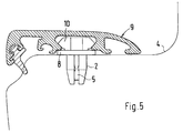
- the fastening clip 1 is at a distance from Platen 8 has an elongated head piece 10, which, when the trim strip 9 is clipped on is at least partially encompassed.
- the head piece 10 locally up to the bore 7 or to the driven expansion pin 5 reaching recess 12 and that on Spreader pin 5 at least one slot-like aligned with the recess 12 Recess 13 is arranged so that when the trim 9 is removed Disassembly of the expansion pin 5 against the insertion direction A by means of a Auxiliary tool is made possible.
- An auxiliary tool is preferably a Screwdriver 18 provided.
- Fig. 4 is the driven, approximately flush with the Top of the head piece 10 extending expansion pin 5 and the inserted Screwdriver 18 shown for dismantling the expansion pin 5.
- the recess 12 is formed according to FIG. 3 on the top of the head piece 10 and designed approximately rectangular. 2, the recess 12 is on the side connected to the central bore 7. The recess 12 could also on one of the be provided on both longitudinal sides 14, 15 of the head piece 10.
- the at least one slot-like recess 13 is approximately perpendicular to the longitudinal axis 16 of the expansion pin 5 aligned. Several, with Recesses 13 arranged axially spaced apart.
- one is in an upper edge region of the expansion pin 5 slot-like recess 13 formed. This only extends in a partial area of the circumference of the expansion pin 5.
- the head piece 10 has on both longitudinal sides Each ends two spaced resilient receiving sections 17 for the clip-on Trim 9 on.
Landscapes
- Engineering & Computer Science (AREA)
- Mechanical Engineering (AREA)
- General Engineering & Computer Science (AREA)
- Connection Of Plates (AREA)
- Insertion Pins And Rivets (AREA)
- Vehicle Interior And Exterior Ornaments, Soundproofing, And Insulation (AREA)
Abstract
Description
- Fig. 1
- eine Seitenansicht auf einen Befestigungsclip für eine Zierleiste,
- Fig. 2
- eine Draufsicht auf den Befestigungsclip,
- Fig. 3
- einen Schnitt nach der Linie III-III der Fig. 2 durch den Befestigungsclip
- Fig. 4
- einen Schnitt entsprechend Fig. 3 mit eingetriebenem Spreizstift und
- Fig. 5
- einen Schnitt nach der Linie V-V der Fig. 2 durch die montierte Zierleiste und den Befestigungsclip.
Claims (7)
- Zierleistenbefestigung, insbesondere für Kraftwagen, mit einem Befestigungsclip, der über ein Fußteil in eine Öffnung eines Bleches oder dergleichen einsetzbar und dort durch einen in eine zentrale Bohrung des Befestigungsclipses eintreibbaren Spreizstift festlegbar ist, wobei der Befestigungsclip eine Auflageplatte und im Abstand davon ein Kopfstück aufweist, das von der Zierleiste wenigstens teilweise umgriffen wird, dadurch gekennzeichnet, daß am Kopfstück (10) örtlich eine bis zum Spreizstift (5) ragende Aussparung (12) vorgesehen ist und daß am Spreizstift (5) zumindest eine schlitzartige Ausnehmung (13) angeordnet ist, so daß eine Demontage des Spreizstiftes (5) entgegen der Einschubrichtung (A) mittels eines Hilfswerkzeuges ermöglicht wird.
- Zierleistenbefestigung nach Anspruch 1, dadurch gekennzeichnet, daß die zumindest eine schlitzartige Ausnehmung (13) etwa rechtwinkelig zur Längsachse (16) des Spreizstiftes (5) ausgerichtet ist.
- Zierleistenbefestigung nach den Ansprüchen 1 und 2, dadurch gekennzeichnet, daß am Spreizstift (5) mehrere mit axialem Abstand zueinander angeordnete schlitzartige Ausnehmungen (13) ausgebildet sind.
- Zierleistenbefestigung nach einem der vorangegangenen Ansprüche, dadurch gekennzeichnet, daß sich die schlitzartigen Ausnehmungen (13) nur in einem Teilbereich des Umfangs des Spreizstiftes (5) erstrecken und mit ihren offenen Seiten der Aussparung (12) zugewandt sind.
- Zierleistenbefestigung nach Anspruch 1, dadurch gekennzeichnet, daß als Hilfswerkzeug ein Schraubendreher (18) dient.
- Zierleistenbefestigung nach Anspruch 1, dadurch gekennzeichnet, daß die Aussparung (12) an einer Längsseite (14, 15) des Kopfstückes (10) oder an die zentrale Bohrung (7) seitlich anschließend zwischen den beiden Längsseiten (14, 15) des Kopfstückes (10) vorgesehen ist.
- Zierleistenbefestigung nach Anspruch 1 oder 6, dadurch gekennzeichnet, daß die Aussparung (12) an der Oberseite des Kopfstückes (10) ausgebildet ist.
Applications Claiming Priority (2)
| Application Number | Priority Date | Filing Date | Title |
|---|---|---|---|
| DE1999154293 DE19954293C1 (de) | 1999-11-11 | 1999-11-11 | Zierleistenbefestigung, insbesondere für Kraftfwagen |
| DE19954293 | 1999-11-11 |
Publications (3)
| Publication Number | Publication Date |
|---|---|
| EP1099865A2 true EP1099865A2 (de) | 2001-05-16 |
| EP1099865A3 EP1099865A3 (de) | 2002-07-03 |
| EP1099865B1 EP1099865B1 (de) | 2006-11-15 |
Family
ID=7928700
Family Applications (1)
| Application Number | Title | Priority Date | Filing Date |
|---|---|---|---|
| EP00120063A Expired - Lifetime EP1099865B1 (de) | 1999-11-11 | 2000-09-15 | Zierleistenbefestigung, insbesondere für Kraftwagen |
Country Status (3)
| Country | Link |
|---|---|
| EP (1) | EP1099865B1 (de) |
| DE (2) | DE19954293C1 (de) |
| ES (1) | ES2272228T3 (de) |
Cited By (1)
| Publication number | Priority date | Publication date | Assignee | Title |
|---|---|---|---|---|
| DE102012019641A1 (de) | 2012-10-06 | 2014-04-10 | Volkswagen Aktiengesellschaft | Verbindungsanordnung zur lösbaren Verbindung von Bauteilen untereinander unter Vermittlung wenigstens eines Hohlniets sowie Hohlniet dazu |
Families Citing this family (5)
| Publication number | Priority date | Publication date | Assignee | Title |
|---|---|---|---|---|
| DE102007015780A1 (de) | 2007-03-30 | 2008-10-02 | Daimler Ag | Vorrichtung und Verfahren zur Befestigung einer Zierleiste an einer Werkstückfläche |
| DE102008032381B4 (de) | 2008-07-09 | 2015-06-25 | Audi Ag | Verfahren zur Demontage einer kombinierten Steck- und Rastverbindung |
| DE102010021049B4 (de) * | 2010-02-23 | 2018-11-08 | Audi Ag | Vorrichtung zur Demontage eines an einer Innenverkleidung eines Kraftfahrzeugs angeordneten Blendenteils |
| FR3017168B1 (fr) | 2014-01-31 | 2016-09-02 | Trw Automotive Elect & Components Gmbh | Attache de fixation de pieces d'habillage, support pour un element de fixation et outil de demontage pour un element de fixation |
| DE102019213689B4 (de) * | 2019-09-10 | 2024-05-02 | Stellantis Auto Sas | Fahrtrichtungsanzeiger eines Kraftfahrzeugs sowie Kraftfahrzeug |
Family Cites Families (3)
| Publication number | Priority date | Publication date | Assignee | Title |
|---|---|---|---|---|
| DE4117114C1 (de) * | 1991-05-25 | 1992-08-06 | A. Raymond Kg, 7850 Loerrach, De | |
| DE4223563C1 (en) * | 1992-07-17 | 1993-09-02 | Mercedes-Benz Aktiengesellschaft, 70327 Stuttgart, De | Cover for tubular component - has protrusion extending into component and containing boss expanding it into engaged position |
| DE19633511C2 (de) * | 1995-09-13 | 1998-04-09 | Illinois Tool Works | Befestigungsmittel |
-
1999
- 1999-11-11 DE DE1999154293 patent/DE19954293C1/de not_active Expired - Fee Related
-
2000
- 2000-09-15 EP EP00120063A patent/EP1099865B1/de not_active Expired - Lifetime
- 2000-09-15 ES ES00120063T patent/ES2272228T3/es not_active Expired - Lifetime
- 2000-09-15 DE DE50013745T patent/DE50013745D1/de not_active Expired - Lifetime
Non-Patent Citations (1)
| Title |
|---|
| None |
Cited By (1)
| Publication number | Priority date | Publication date | Assignee | Title |
|---|---|---|---|---|
| DE102012019641A1 (de) | 2012-10-06 | 2014-04-10 | Volkswagen Aktiengesellschaft | Verbindungsanordnung zur lösbaren Verbindung von Bauteilen untereinander unter Vermittlung wenigstens eines Hohlniets sowie Hohlniet dazu |
Also Published As
| Publication number | Publication date |
|---|---|
| DE50013745D1 (de) | 2006-12-28 |
| ES2272228T3 (es) | 2007-05-01 |
| DE19954293C1 (de) | 2001-06-21 |
| EP1099865B1 (de) | 2006-11-15 |
| EP1099865A3 (de) | 2002-07-03 |
Similar Documents
| Publication | Publication Date | Title |
|---|---|---|
| EP1958825B1 (de) | Befestigungsvorrichtung | |
| DE19943293C2 (de) | Halteeinrichtung für einen Ultraschallwandler an einem Aussenteil eines Kraftfahrzeuges | |
| EP0430022B1 (de) | Bauteilbefestigung in Kraftfahrzeugkarosserien mit einer Blechmutter und einem Schraubenbolzen | |
| DE19543830A1 (de) | Kunststoff-Befestigungselement, insbesondere für eine Fahrzeugverkleidung | |
| DE102008033307A1 (de) | Befestigungsvorrichtung | |
| DE19619087A1 (de) | Befestigungsvorrichtung | |
| DE102004016810A1 (de) | Scheibenwischvorrichtung, insbesondere für ein Kraftfahrzeug | |
| DE3430121A1 (de) | Instrumententafel fuer kraftfahrzeuge | |
| DE10329574A1 (de) | Scheibenwischvorrichtung für ein Kraftfahrzeug | |
| EP1873016A1 (de) | Befestigungseinrichtung für ein Anbauteil | |
| DE10242787B3 (de) | Lösbare Verbindung zwischen zwei angrenzenden Bauteilen, insbesondere Aussenhautteilen einer Fahrzeugkarosserie | |
| DE19741062A1 (de) | Mehrfunktionsschiene | |
| DE4423440B4 (de) | Vorrichtung zur Befestigung einer Fensterscheibe eines Kraftfahrzeugs an der Führungsvorrichtung eines Fensterhebers | |
| DE3902399A1 (de) | Zierleistenhalter | |
| DE202004020237U1 (de) | Kunststoffbauteil | |
| DE19954293C1 (de) | Zierleistenbefestigung, insbesondere für Kraftfwagen | |
| DE4134201C1 (en) | Covered internal trimming fixture for car bodywork - uses form-fitting snap arrangement allowing release without damage for servicing | |
| DE3009704A1 (de) | Vorrichtung zur gelenkigen halterung eines scheibenwischer-wischblattes an einem wischarm | |
| DE19547070A1 (de) | Befestigungsvorrichtung mit einem Halteelement für eine Leitung | |
| DE102009035148B4 (de) | Seitenführungselement | |
| EP0672558A1 (de) | Verschlusseinrichtung zum lösbaren Verbinden zweier Bauteile | |
| EP0593909A1 (de) | Kunststoff-Halteclip für Schutz-, Zierleisten oder dergleichen, insbesondere an Kraftfahrzeugen | |
| DE10223383A1 (de) | Gehäuse mit Rastvorrichtung zur Befestigung an einer Trägerplatte | |
| DE10149483A1 (de) | Befestigungsvorrichtung zur Herstellung eines Bauteilverbundes | |
| DE102005019078B4 (de) | Vorrichtung zur Montage eines Kraftfahrzeugsitzes |
Legal Events
| Date | Code | Title | Description |
|---|---|---|---|
| PUAI | Public reference made under article 153(3) epc to a published international application that has entered the european phase |
Free format text: ORIGINAL CODE: 0009012 |
|
| AK | Designated contracting states |
Kind code of ref document: A2 Designated state(s): AT BE CH CY DE DK ES FI FR GB GR IE IT LI LU MC NL PT SE |
|
| AX | Request for extension of the european patent |
Free format text: AL;LT;LV;MK;RO;SI |
|
| PUAL | Search report despatched |
Free format text: ORIGINAL CODE: 0009013 |
|
| AK | Designated contracting states |
Kind code of ref document: A3 Designated state(s): AT BE CH CY DE DK ES FI FR GB GR IE IT LI LU MC NL PT SE |
|
| AX | Request for extension of the european patent |
Free format text: AL;LT;LV;MK;RO;SI |
|
| RIC1 | Information provided on ipc code assigned before grant |
Free format text: 7F 16B 19/10 A, 7B 60R 13/02 B, 7B 60R 13/04 B, 7F 16B 5/12 B |
|
| 17P | Request for examination filed |
Effective date: 20030103 |
|
| AKX | Designation fees paid |
Designated state(s): DE ES FR GB IT |
|
| GRAP | Despatch of communication of intention to grant a patent |
Free format text: ORIGINAL CODE: EPIDOSNIGR1 |
|
| GRAS | Grant fee paid |
Free format text: ORIGINAL CODE: EPIDOSNIGR3 |
|
| GRAA | (expected) grant |
Free format text: ORIGINAL CODE: 0009210 |
|
| AK | Designated contracting states |
Kind code of ref document: B1 Designated state(s): DE ES FR GB IT |
|
| REG | Reference to a national code |
Ref country code: GB Ref legal event code: FG4D Free format text: NOT ENGLISH |
|
| REF | Corresponds to: |
Ref document number: 50013745 Country of ref document: DE Date of ref document: 20061228 Kind code of ref document: P |
|
| GBT | Gb: translation of ep patent filed (gb section 77(6)(a)/1977) |
Effective date: 20070130 |
|
| ET | Fr: translation filed | ||
| REG | Reference to a national code |
Ref country code: ES Ref legal event code: FG2A Ref document number: 2272228 Country of ref document: ES Kind code of ref document: T3 |
|
| PLBE | No opposition filed within time limit |
Free format text: ORIGINAL CODE: 0009261 |
|
| STAA | Information on the status of an ep patent application or granted ep patent |
Free format text: STATUS: NO OPPOSITION FILED WITHIN TIME LIMIT |
|
| 26N | No opposition filed |
Effective date: 20070817 |
|
| PGFP | Annual fee paid to national office [announced via postgrant information from national office to epo] |
Ref country code: GB Payment date: 20080918 Year of fee payment: 9 |
|
| PGFP | Annual fee paid to national office [announced via postgrant information from national office to epo] |
Ref country code: ES Payment date: 20080929 Year of fee payment: 9 |
|
| REG | Reference to a national code |
Ref country code: FR Ref legal event code: TP |
|
| REG | Reference to a national code |
Ref country code: FR Ref legal event code: CD |
|
| GBPC | Gb: european patent ceased through non-payment of renewal fee |
Effective date: 20090915 |
|
| PG25 | Lapsed in a contracting state [announced via postgrant information from national office to epo] |
Ref country code: GB Free format text: LAPSE BECAUSE OF NON-PAYMENT OF DUE FEES Effective date: 20090915 |
|
| PGFP | Annual fee paid to national office [announced via postgrant information from national office to epo] |
Ref country code: IT Payment date: 20100924 Year of fee payment: 11 Ref country code: FR Payment date: 20101005 Year of fee payment: 11 |
|
| REG | Reference to a national code |
Ref country code: FR Ref legal event code: TP |
|
| REG | Reference to a national code |
Ref country code: ES Ref legal event code: FD2A Effective date: 20110714 |
|
| PG25 | Lapsed in a contracting state [announced via postgrant information from national office to epo] |
Ref country code: ES Free format text: LAPSE BECAUSE OF NON-PAYMENT OF DUE FEES Effective date: 20110704 |
|
| PG25 | Lapsed in a contracting state [announced via postgrant information from national office to epo] |
Ref country code: ES Free format text: LAPSE BECAUSE OF NON-PAYMENT OF DUE FEES Effective date: 20090916 |
|
| PG25 | Lapsed in a contracting state [announced via postgrant information from national office to epo] |
Ref country code: IT Free format text: LAPSE BECAUSE OF NON-PAYMENT OF DUE FEES Effective date: 20110915 |
|
| REG | Reference to a national code |
Ref country code: FR Ref legal event code: ST Effective date: 20120531 |
|
| PG25 | Lapsed in a contracting state [announced via postgrant information from national office to epo] |
Ref country code: FR Free format text: LAPSE BECAUSE OF NON-PAYMENT OF DUE FEES Effective date: 20110930 |
|
| PGFP | Annual fee paid to national office [announced via postgrant information from national office to epo] |
Ref country code: DE Payment date: 20140815 Year of fee payment: 15 |
|
| REG | Reference to a national code |
Ref country code: DE Ref legal event code: R119 Ref document number: 50013745 Country of ref document: DE |
|
| PG25 | Lapsed in a contracting state [announced via postgrant information from national office to epo] |
Ref country code: DE Free format text: LAPSE BECAUSE OF NON-PAYMENT OF DUE FEES Effective date: 20160401 |