EP1099828A2 - Verfahren zum Anschwingen eines elektromagnetischen Aktuators - Google Patents
Verfahren zum Anschwingen eines elektromagnetischen Aktuators Download PDFInfo
- Publication number
- EP1099828A2 EP1099828A2 EP00121922A EP00121922A EP1099828A2 EP 1099828 A2 EP1099828 A2 EP 1099828A2 EP 00121922 A EP00121922 A EP 00121922A EP 00121922 A EP00121922 A EP 00121922A EP 1099828 A2 EP1099828 A2 EP 1099828A2
- Authority
- EP
- European Patent Office
- Prior art keywords
- spring
- voltage
- armature
- frequency
- mass system
- Prior art date
- Legal status (The legal status is an assumption and is not a legal conclusion. Google has not performed a legal analysis and makes no representation as to the accuracy of the status listed.)
- Granted
Links
Images


Classifications
-
- F—MECHANICAL ENGINEERING; LIGHTING; HEATING; WEAPONS; BLASTING
- F01—MACHINES OR ENGINES IN GENERAL; ENGINE PLANTS IN GENERAL; STEAM ENGINES
- F01L—CYCLICALLY OPERATING VALVES FOR MACHINES OR ENGINES
- F01L9/00—Valve-gear or valve arrangements actuated non-mechanically
- F01L9/20—Valve-gear or valve arrangements actuated non-mechanically by electric means
-
- Y—GENERAL TAGGING OF NEW TECHNOLOGICAL DEVELOPMENTS; GENERAL TAGGING OF CROSS-SECTIONAL TECHNOLOGIES SPANNING OVER SEVERAL SECTIONS OF THE IPC; TECHNICAL SUBJECTS COVERED BY FORMER USPC CROSS-REFERENCE ART COLLECTIONS [XRACs] AND DIGESTS
- Y10—TECHNICAL SUBJECTS COVERED BY FORMER USPC
- Y10T—TECHNICAL SUBJECTS COVERED BY FORMER US CLASSIFICATION
- Y10T137/00—Fluid handling
- Y10T137/0318—Processes
Definitions
- the invention relates to a method for oscillating a switching element, in particular an internal combustion engine lift valve, actuating electromagnetic Actuator, in which an acting on the switching element Armature oscillating between two electro-magnetic coils the force of at least one return spring by alternating energization of the Electromagnetic coils is moved so that the switching element with the armature and the return springs an oscillating spring-mass system represents, and starting from the idle state of the system in which the armature of the return springs is essentially in the middle between this magnetic coils is held to swing this spring-mass system the electro-magnetic coils alternately by applying electrical alternating voltage can be excited by a certain frequency.
- EP 0 118 591 B1 reference is made to the technical environment DE 33 07 070 C2 referenced.
- an electromagnetic actuator with the features of claim 1 is the electromagnetically actuated valve train of internal combustion engines, i.e. the gas exchange stroke valves of a reciprocating piston internal combustion engine are desired by such actuators Actuated wise, i.e. oscillatingly opened and closed.
- the electromagnetically actuated valve train are the globe valves individually or in groups via electromechanical actuators, the so-called Actuators moved, the time for opening and closing each stroke valve can be chosen essentially completely freely.
- the valve timing of the internal combustion engine can be optimally matched to the current one Operating status (this is defined by speed and load) and on the respective requirements with regard to consumption, torque, emissions, Comfort and responsiveness of a driven by the internal combustion engine Be adapted to the vehicle.
- the essential components of a known actuator for actuating the lift valves of an internal combustion engine are an armature and two electromagnets for holding the armature in the "lift valve open” or “lift valve closed” position with the associated solenoid coils, and also return springs for the movement of the armature between the positions "lift valve open” and “lift valve closed”.
- FIG. 1 shows such an actuator with an associated lift valve in the two possible end positions of the lift valve and actuator armature, and the course of the armature stroke between the two states or positions of the actuator / lift valve unit shown z or armature path between the two solenoid coils over time t is shown in simplified form.
- FIG. 1 the closing process of an internal combustion engine lift valve is shown, which is designated by the reference number 1 and which in this case moves in the direction of its valve seat 30.
- a valve closing spring or first return spring 2a acts on this lifting valve 1, furthermore the actuator designated in its entirety with 4 acts on the stem of the lifting valve 1 - here with the interposition of a (not absolutely necessary) hydraulic valve lash compensation element 3.
- this consists of a push rod 4c acting on the stem of the lift valve 1, which carries an armature 4d which is guided in an oscillating, longitudinally displaceable manner between the electromagnetic coils 4a, 4b.
- a valve opening spring or second return spring 2b also acts on the end of the push rod 4c facing away from the stem of the lifting valve 1.
- Is on the left 1 shows the first end position of this oscillatory system, in which the lift valve 1 is fully open and the armature 4d on of the lower electromagnetic coil 4b.
- On the right is in Figure 1 second end position of the vibratory system shown, in which the lift valve 1 is completely closed and the armature 4d on the upper one Electromagnetic coil 4a is present. It is in these two end positions the armature 4d by suitable excitation or de-excitation of the respective magnetic coils 4a, 4b moves.
- the armature 4d When the system is idle, i.e. if none of the solenoids 4a, 4b is excited, the armature 4d is located substantially in the middle between the two solenoids 4a, 4b and is suitable in this position by the designed return springs 2a, 2b held. Starting from this Rest position must be required for this system to operate, i.e. For a desired oscillating actuation of the lift valve 1 the whole Spring mass system can be swung.
- the object of the present invention is to provide a remedial measure for the problems described.
- the solution to this problem is characterized in that an essentially sinusoidal or similar AC voltage is applied to the electro-magnetic coils instead of the previously generally substantially rectangular shape of the AC voltage over time, either in the form of a variable one constant voltage curve or in the form of a corresponding changeable pulse width modulated voltage curve.
- Advantageous further developments are included in the subclaims.
- the voltage profile of the exciting AC voltage ie alternating voltage applied to the two electromagnetic coils at a certain frequency
- the present invention proposes an essentially sinusoidal or similar course of the applied alternating voltage U, as is shown by way of example in FIG. 2a over time t. This can be a constant voltage curve (as in FIG.
- electromagnetic actuator according to the preamble of claim 1 not more with periodic rectangular voltage pulses and also not more absolutely to excite with the natural frequency of the spring-mass system, but a suitable input signal with a non-linear one Vibration system adapted periodic course - essentially a sinusoidal or similar course that is changeable - to use for swinging.
- the amplitude or pulse width duty cycle of the selected course of the AC voltage results derive from the theory of anharmonic vibrations (and generally does not match the natural frequency of the spring-mass system match).
- the frequency of the overall system generally depends on the amplitude of vibration, so that consequently the frequency of the AC voltage depending on the Vibration amplitude of the armature can be changed.
- the damping contained in the entire actuator Spring-mass vibrator can be temperature-dependent, in particular if viscosity influences one with part of the overall system lubricating oil coming into contact play a role. This results in a Shift of the system resonance frequency, with the result that the electromagnetic actuator at different ambient temperatures must be swung at different frequencies or only with different frequencies can be swung up. When determining the frequency of the proposed periodic, substantially sinusoidal AC voltage can therefore influence such temperatures be taken into account. This leads to an unnecessarily high energy consumption of the avoided electromagnetic actuator.
- the changeable, essentially sinusoidal or similar stimulating AC voltage to the following further thought Be taken into account. It is even based on it of the linear spring-mass system desirable that when starting with a periodic adapted to the vibratory system Force course is excited.
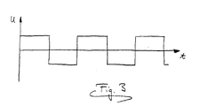
- the one already mentioned and shown in FIG. 3 previous rectangular course of the AC voltage has accordingly a Fourier analysis has a relatively high harmonic content, so that in particular also on a real actuator, which as already explained represents a highly nonlinear system, possibly undesirable Harmonics are excited in the actuator, so that the Energy consumption is unnecessarily high.
- the waveform or sine shape of the exciting voltage to be chosen such that the fundamental vibration alone, but not one Harmonics of the spring-mass system is excited.
- the method according to the invention is thus characterized in particular by a lower energy consumption and thus a lower need electrical power.
- to start the Actuator requires fewer amplitudes, although it should also be pointed out that of course details, for example, of the actuator actually used deviating from the above description or from the simplified figure representation can be without leaving the content of the claims.
Landscapes
- Engineering & Computer Science (AREA)
- Mechanical Engineering (AREA)
- General Engineering & Computer Science (AREA)
- Valve Device For Special Equipments (AREA)
- Reciprocating, Oscillating Or Vibrating Motors (AREA)
Abstract
Description
Die Lösung dieser Aufgabe ist dadurch gekennzeichnet, daß anstelle des bisher üblichen im wesentlichen rechteckförmigen Verlaufes der Wechsel-Spannung über der Zeit eine im wesentlichen sinusförmige oder einer solchen ähnliche Wechsel-Spannung an die Elektro-Magnetspulen angelegt wird, und zwar entweder in Form eines veränderbaren stetigen Spannungsverlaufes oder in Form eines entsprechenden veränderbaren pulsweitenmodulierten Spannungsverlaufs. Vorteilhafte Weiterbildungen sind Inhalt der Unteransprüche.
Claims (5)
- Verfahren zum Anschwingen eines ein Schaltelement, insbesondere ein Brennkraftmaschinen-Hubventil (1) betätigenden elektromagnetischen Aktuators (4), in welchem ein auf das Schaltelement einwirkender Anker (4d) oszillierend zwischen zwei Elektro-Magnetspulen (4a, 4b) jeweils gegen die Kraft zumindest einer Rückstellfeder (2a, 2b) durch alternierende Bestromung der Elektromagnet-Spulen (4a, 4b) bewegt wird, so daß das Schaltelement mit dem Anker (4d) und den Rückstellfedern (2a, 2b) ein schwingungsfähiges Feder-Masse-System darstellt,
und wobei ausgehend vom Ruhezustand des Systems, in welchem der Anker (4d) von den Rückstellfedern (2a, 2b) im wesentlichen in der Mitte zwischen diesen Magnetspulen (4a, 4b) gehalten wird, zum Anschwingen dieses Feder-Masse-Systemes die Elektro-Magnetspulen (4a, 4b) abwechselnd durch Beaufschlagung mit elektrischer Wechsel-Spannung von bestimmter Frequenz erregt werden, dadurch gekennzeichnet, daß anstelle des bisher üblichen im wesentlichen rechteckförmigen Verlaufes der Wechsel-Spannung (U) über der Zeit (t) eine im wesentlichen sinusförmige Wechsel-Spannung (U) an die Elektro-Magnetspulen (4a, 4b) angelegt wird, und zwar entweder in Form eines veränderbaren stetigen Spannungsverlaufes oder in Form eines entsprechenden veränderbaren pulsweitenmodulierten Spannungsverlaufes. - Verfahren nach Anspruch 1,
dadurch gekennzeichnet, daß sich die Frequenz der Wechsel-Spannung aus der Theorie der anharmonischen Schwingungen ergibt und im allgemeinen nicht mit der Eigenfrequenz des Feder-Masse-Systemes übereinstimmt. - Verfahren nach Anspruch 1 oder 2,
dadurch gekennzeichnet, daß die Frequenz der Wechselspannung in Abhängigkeit von der Schwingungsamplitude des Ankers verändert wird. - Verfahren nach einem der vorangegangenen Ansprüche,
dadurch gekennzeichnet, daß bei der Bestimmung der Frequenz der Wechsel-Spannung eine insbesondere temperaturabhängige Veränderung der Dämpfung des Feder-Masse-Systemes und damit von dessen Resonanzfrequenz berücksichtigt wird. - Verfahren nach einem der vorangegangenen Ansprüche,
dadurch gekennzeichnet, daß die Sinusform oder Wellenform der Wechsel-Spannung derart gewählt wird, das alleine die Grundschwingung, nicht jedoch eine Oberschwingung des Feder-Masse-Systemes angeregt wird.
Applications Claiming Priority (2)
| Application Number | Priority Date | Filing Date | Title |
|---|---|---|---|
| DE19954416A DE19954416A1 (de) | 1999-11-12 | 1999-11-12 | Verfahren zum Anschwingen eines elektromagnetischen Aktuators |
| DE19954416 | 1999-11-12 |
Publications (3)
| Publication Number | Publication Date |
|---|---|
| EP1099828A2 true EP1099828A2 (de) | 2001-05-16 |
| EP1099828A3 EP1099828A3 (de) | 2002-03-27 |
| EP1099828B1 EP1099828B1 (de) | 2004-03-31 |
Family
ID=7928782
Family Applications (1)
| Application Number | Title | Priority Date | Filing Date |
|---|---|---|---|
| EP00121922A Expired - Lifetime EP1099828B1 (de) | 1999-11-12 | 2000-10-07 | Verfahren zum Anschwingen eines elektromagnetischen Aktuators |
Country Status (5)
| Country | Link |
|---|---|
| US (1) | US6390113B1 (de) |
| EP (1) | EP1099828B1 (de) |
| JP (1) | JP2001217123A (de) |
| DE (2) | DE19954416A1 (de) |
| ES (1) | ES2215537T3 (de) |
Cited By (5)
| Publication number | Priority date | Publication date | Assignee | Title |
|---|---|---|---|---|
| EP1271571A1 (de) * | 2001-06-19 | 2003-01-02 | MAGNETI MARELLI POWERTRAIN S.p.A. | Regelverfahren eines elektromagnetischen Aktuators zur Steuerung eines Motorventils von Ruhestellung |
| FR2853002A1 (fr) * | 2003-03-25 | 2004-10-01 | Toyota Motor Co Ltd | Systeme et procede de commande d'une soupape actionnee electromagnetiquement |
| US6920029B2 (en) | 2001-06-19 | 2005-07-19 | Magneti Marelli Powertrain S.P.A. | Control method for an electromagnetic actuator for the control of a valve of an engine from an abutment condition |
| DE102005024173A1 (de) * | 2005-05-23 | 2006-11-30 | Volkswagen Ag | Verfahren zur Steuerung von Schaltelementen |
| CN107332424A (zh) * | 2017-08-15 | 2017-11-07 | 李良杰 | 程控直线电机 |
Families Citing this family (3)
| Publication number | Priority date | Publication date | Assignee | Title |
|---|---|---|---|---|
| DE10332489A1 (de) * | 2003-07-16 | 2005-02-24 | Mahle Filtersysteme Gmbh | Verfahren zum Anschwingen einer elektromagnetischen Stelleinrichtung |
| DE102012011934B4 (de) * | 2012-06-18 | 2014-07-10 | Krohne Messtechnik Gmbh | Verfahren zum Betreiben eines Resonazmesssystems und diesbezügliche Resonanzmesssystem |
| US10234496B2 (en) * | 2016-02-16 | 2019-03-19 | Woodward, Inc. | Detection of valve open time for solenoid operated fuel injectors |
Family Cites Families (9)
| Publication number | Priority date | Publication date | Assignee | Title |
|---|---|---|---|---|
| DE3307070C2 (de) * | 1983-03-01 | 1985-11-28 | FEV Forschungsgesellschaft für Energietechnik und Verbrennungsmotoren mbH, 5100 Aachen | Stelleinrichtung für ein zwischen zwei Endstellungen verstellbares Schaltelement |
| DE3307683C1 (de) * | 1983-03-04 | 1984-07-26 | Klöckner, Wolfgang, Dr., 8033 Krailling | Verfahren zum Aktivieren einer elektromagnetisch arbeitenden Stelleinrichtung sowie Vorrichtung zum Durchfuehren des Verfahrens |
| DE3402118A1 (de) * | 1984-01-23 | 1985-07-25 | Robert Bosch Gmbh, 7000 Stuttgart | Steuerventil |
| JP2772534B2 (ja) * | 1989-02-20 | 1998-07-02 | 株式会社いすゞセラミックス研究所 | 電磁力バルブ駆動装置 |
| DE19544207C2 (de) * | 1995-11-28 | 2001-03-01 | Univ Dresden Tech | Verfahren zur modellbasierten Messung und Regelung von Bewegungen an elektromagnetischen Aktoren |
| DE29600866U1 (de) * | 1996-01-19 | 1996-03-07 | Festo Kg, 73734 Esslingen | Schaltungsanordnung zur Steuerung von Magnetventilen |
| DE19723931A1 (de) * | 1997-06-06 | 1998-12-10 | Siemens Ag | Einrichtung zum Steuern eines elektromechanischen Stellgeräts |
| DE19739840C2 (de) * | 1997-09-11 | 2002-11-28 | Daimler Chrysler Ag | Verfahren zur Steuerung einer elektromagnetisch betätigbaren Stellvorrichtung, insbesondere eines Ventils für Brennkraftmaschinen |
| US6005763A (en) * | 1998-02-20 | 1999-12-21 | Sturman Industries, Inc. | Pulsed-energy controllers and methods of operation thereof |
-
1999
- 1999-11-12 DE DE19954416A patent/DE19954416A1/de not_active Withdrawn
-
2000
- 2000-10-07 DE DE50005882T patent/DE50005882D1/de not_active Expired - Fee Related
- 2000-10-07 ES ES00121922T patent/ES2215537T3/es not_active Expired - Lifetime
- 2000-10-07 EP EP00121922A patent/EP1099828B1/de not_active Expired - Lifetime
- 2000-11-09 JP JP2000341792A patent/JP2001217123A/ja active Pending
- 2000-11-13 US US09/709,333 patent/US6390113B1/en not_active Expired - Fee Related
Cited By (6)
| Publication number | Priority date | Publication date | Assignee | Title |
|---|---|---|---|---|
| EP1271571A1 (de) * | 2001-06-19 | 2003-01-02 | MAGNETI MARELLI POWERTRAIN S.p.A. | Regelverfahren eines elektromagnetischen Aktuators zur Steuerung eines Motorventils von Ruhestellung |
| US6659422B2 (en) | 2001-06-19 | 2003-12-09 | Magnetti Marelli Powerstrain S.P.A. | Control method for an electromagnetic actuator for the control of a valve of an engine from a rest condition |
| US6920029B2 (en) | 2001-06-19 | 2005-07-19 | Magneti Marelli Powertrain S.P.A. | Control method for an electromagnetic actuator for the control of a valve of an engine from an abutment condition |
| FR2853002A1 (fr) * | 2003-03-25 | 2004-10-01 | Toyota Motor Co Ltd | Systeme et procede de commande d'une soupape actionnee electromagnetiquement |
| DE102005024173A1 (de) * | 2005-05-23 | 2006-11-30 | Volkswagen Ag | Verfahren zur Steuerung von Schaltelementen |
| CN107332424A (zh) * | 2017-08-15 | 2017-11-07 | 李良杰 | 程控直线电机 |
Also Published As
| Publication number | Publication date |
|---|---|
| US6390113B1 (en) | 2002-05-21 |
| DE19954416A1 (de) | 2001-05-17 |
| EP1099828B1 (de) | 2004-03-31 |
| ES2215537T3 (es) | 2004-10-16 |
| JP2001217123A (ja) | 2001-08-10 |
| EP1099828A3 (de) | 2002-03-27 |
| DE50005882D1 (de) | 2004-05-06 |
Similar Documents
| Publication | Publication Date | Title |
|---|---|---|
| DE3307070C2 (de) | Stelleinrichtung für ein zwischen zwei Endstellungen verstellbares Schaltelement | |
| EP0973178B1 (de) | Verfahren zur Bewegungssteuerung eines Ankers eines elektromagnetischen Aktuators | |
| DE19640659B4 (de) | Verfahren zur Betätigung eines elektromagnetischen Aktuators mit Beeinflussung des Spulenstroms während der Ankerbewegung | |
| EP0405189B1 (de) | Elektromagnetisch arbeitende Stelleinrichtung | |
| DE19526681B4 (de) | Verfahren zur zeitgenauen Steuerung der Ankerbewegung eines elektromagnetisch betätigbaren Stellmittels | |
| EP1262639A9 (de) | Verfahren zur Steuerung einer elektromagnetisch betätigten Stellvorrichtung, insbesondere zur Steuerung eines Gaswechselventils einer Brennkraftmaschine | |
| DE3024109A1 (de) | Elektromagnetisch arbeitende stelleinrichtung | |
| DE60115766T2 (de) | Selbstkompensierender piezoelektrischer Aktuator für ein Steuerventil | |
| EP1099828B1 (de) | Verfahren zum Anschwingen eines elektromagnetischen Aktuators | |
| DE19960796A1 (de) | System zum Steuern eines elektromagnetisch betätigten Ventils | |
| EP1134364A2 (de) | Verfahren zum Betrieb eines elektromagnetischen Aktors | |
| EP0973177B1 (de) | Verfahren zur Bewegungssteuerung eines Ankers eines elektromagnetischen Aktuators | |
| DE102011016895A1 (de) | Verfahren zur Bestimmung des Verschleißzustandes eines elektromagnetischen Aktors während dessen Betriebs | |
| EP1187972B1 (de) | Elektromagnetischer aktuator und verfahren zur justierung des elektromagnetischen aktuators | |
| EP0935054A2 (de) | Elektromagnetischer Aktuator | |
| DE19841124A1 (de) | Elektromagnetisch betätigbares Gaswechselventil für eine Kolbenbrennkraftmaschine mit pneumatischen Rückstellfedern | |
| DE102014202428A1 (de) | Elektrohydraulisches Schaltventil und Verfahren zum geräuscharmen Ansteuern eines solchen | |
| DE19529152B4 (de) | Aus der Ruhelage selbstanziehender elektromagnetischer Aktuator | |
| DE10206031B4 (de) | Verfahren zur Steuerung der Bewegung eines Ankers eines elektromagnetischen Aktuators | |
| DE102006025397B4 (de) | Elektromagnetisch angetriebenes Ventil | |
| DE19838118A1 (de) | Elektromagnetischer Aktuator für ein Brennkraftmaschinen-Hubventil | |
| DE10325706B4 (de) | Verfahren zur Steuerung der Bewegung eines Ankers eines elektromagnetischen Aktuators | |
| DE10318244A1 (de) | Verfahren zur Steuerung der Bewegung eines Ankers eines elektromagnetischen Aktuators | |
| DE19852169C1 (de) | Verfahren zum Betrieb eines Aktors zur elektromagnetischen Ventilsteuerung bei Brennkraftmaschinen | |
| WO2012084682A1 (de) | Magnetodynamischer aktor und verfahren zur betätigung eines kraftstoffeinspritzventils |
Legal Events
| Date | Code | Title | Description |
|---|---|---|---|
| PUAI | Public reference made under article 153(3) epc to a published international application that has entered the european phase |
Free format text: ORIGINAL CODE: 0009012 |
|
| AK | Designated contracting states |
Kind code of ref document: A2 Designated state(s): AT BE CH CY DE DK ES FI FR GB GR IE IT LI LU MC NL PT SE Kind code of ref document: A2 Designated state(s): DE ES FR GB IT SE |
|
| AX | Request for extension of the european patent |
Free format text: AL;LT;LV;MK;RO;SI |
|
| PUAL | Search report despatched |
Free format text: ORIGINAL CODE: 0009013 |
|
| AK | Designated contracting states |
Kind code of ref document: A3 Designated state(s): AT BE CH CY DE DK ES FI FR GB GR IE IT LI LU MC NL PT SE |
|
| AX | Request for extension of the european patent |
Free format text: AL;LT;LV;MK;RO;SI |
|
| AKX | Designation fees paid | ||
| 17P | Request for examination filed |
Effective date: 20021114 |
|
| RBV | Designated contracting states (corrected) |
Designated state(s): DE ES FR GB IT SE |
|
| R17P | Request for examination filed (corrected) |
Effective date: 20020214 |
|
| RBV | Designated contracting states (corrected) |
Designated state(s): DE ES FR GB IT SE |
|
| GRAP | Despatch of communication of intention to grant a patent |
Free format text: ORIGINAL CODE: EPIDOSNIGR1 |
|
| GRAS | Grant fee paid |
Free format text: ORIGINAL CODE: EPIDOSNIGR3 |
|
| GRAA | (expected) grant |
Free format text: ORIGINAL CODE: 0009210 |
|
| AK | Designated contracting states |
Kind code of ref document: B1 Designated state(s): DE ES FR GB IT SE |
|
| REG | Reference to a national code |
Ref country code: GB Ref legal event code: FG4D Free format text: NOT ENGLISH |
|
| GBT | Gb: translation of ep patent filed (gb section 77(6)(a)/1977) | ||
| REG | Reference to a national code |
Ref country code: IE Ref legal event code: FG4D Free format text: GERMAN |
|
| REF | Corresponds to: |
Ref document number: 50005882 Country of ref document: DE Date of ref document: 20040506 Kind code of ref document: P |
|
| REG | Reference to a national code |
Ref country code: SE Ref legal event code: TRGR |
|
| PGFP | Annual fee paid to national office [announced via postgrant information from national office to epo] |
Ref country code: ES Payment date: 20041007 Year of fee payment: 5 |
|
| REG | Reference to a national code |
Ref country code: ES Ref legal event code: FG2A Ref document number: 2215537 Country of ref document: ES Kind code of ref document: T3 |
|
| PGFP | Annual fee paid to national office [announced via postgrant information from national office to epo] |
Ref country code: SE Payment date: 20041027 Year of fee payment: 5 |
|
| ET | Fr: translation filed | ||
| REG | Reference to a national code |
Ref country code: IE Ref legal event code: FD4D |
|
| PLBE | No opposition filed within time limit |
Free format text: ORIGINAL CODE: 0009261 |
|
| STAA | Information on the status of an ep patent application or granted ep patent |
Free format text: STATUS: NO OPPOSITION FILED WITHIN TIME LIMIT |
|
| 26N | No opposition filed |
Effective date: 20050104 |
|
| PG25 | Lapsed in a contracting state [announced via postgrant information from national office to epo] |
Ref country code: IT Free format text: LAPSE BECAUSE OF NON-PAYMENT OF DUE FEES Effective date: 20051007 |
|
| PG25 | Lapsed in a contracting state [announced via postgrant information from national office to epo] |
Ref country code: SE Free format text: LAPSE BECAUSE OF NON-PAYMENT OF DUE FEES Effective date: 20051008 Ref country code: ES Free format text: LAPSE BECAUSE OF NON-PAYMENT OF DUE FEES Effective date: 20051008 |
|
| EUG | Se: european patent has lapsed | ||
| REG | Reference to a national code |
Ref country code: ES Ref legal event code: FD2A Effective date: 20051008 |
|
| PGFP | Annual fee paid to national office [announced via postgrant information from national office to epo] |
Ref country code: DE Payment date: 20071129 Year of fee payment: 8 |
|
| PGFP | Annual fee paid to national office [announced via postgrant information from national office to epo] |
Ref country code: FR Payment date: 20071029 Year of fee payment: 8 Ref country code: GB Payment date: 20071031 Year of fee payment: 8 |
|
| GBPC | Gb: european patent ceased through non-payment of renewal fee |
Effective date: 20081007 |
|
| REG | Reference to a national code |
Ref country code: FR Ref legal event code: ST Effective date: 20090630 |
|
| PG25 | Lapsed in a contracting state [announced via postgrant information from national office to epo] |
Ref country code: DE Free format text: LAPSE BECAUSE OF NON-PAYMENT OF DUE FEES Effective date: 20090501 |
|
| PG25 | Lapsed in a contracting state [announced via postgrant information from national office to epo] |
Ref country code: FR Free format text: LAPSE BECAUSE OF NON-PAYMENT OF DUE FEES Effective date: 20081031 |
|
| PG25 | Lapsed in a contracting state [announced via postgrant information from national office to epo] |
Ref country code: GB Free format text: LAPSE BECAUSE OF NON-PAYMENT OF DUE FEES Effective date: 20081007 |