EP1099809A2 - Burial vault - Google Patents
Burial vault Download PDFInfo
- Publication number
- EP1099809A2 EP1099809A2 EP00124145A EP00124145A EP1099809A2 EP 1099809 A2 EP1099809 A2 EP 1099809A2 EP 00124145 A EP00124145 A EP 00124145A EP 00124145 A EP00124145 A EP 00124145A EP 1099809 A2 EP1099809 A2 EP 1099809A2
- Authority
- EP
- European Patent Office
- Prior art keywords
- trough
- sleeve
- hole
- floor pan
- peripheral walls
- Prior art date
- Legal status (The legal status is an assumption and is not a legal conclusion. Google has not performed a legal analysis and makes no representation as to the accuracy of the status listed.)
- Withdrawn
Links
Images


Classifications
-
- E—FIXED CONSTRUCTIONS
- E04—BUILDING
- E04H—BUILDINGS OR LIKE STRUCTURES FOR PARTICULAR PURPOSES; SWIMMING OR SPLASH BATHS OR POOLS; MASTS; FENCING; TENTS OR CANOPIES, IN GENERAL
- E04H13/00—Monuments; Tombs; Burial vaults; Columbaria
- E04H13/005—Ventilation systems therefor
Definitions
- Grave chambers made of precast concrete used. This can be refilled after the decomposition has been completed, if the leg remains of the previous occupancy on one suitable place, for example in a bone chamber, have been filed.
- These burial chambers made of precast concrete are available in different versions roughly divide into open burial chambers and closed burial chambers can.
- An open burial chamber is from DE 35 37 367.9 A1 known. It has several chamber rings in one Pit to be stacked on top of each other by being circulating Heels on both the top and bottom of the chamber rings be led among themselves. At the bottom there is a base plate on which the chamber rings are loose are put on. On the top chamber ring there are ceiling panels hung up after the interior of the burial chambers complete at the top. These ceiling tiles are about 60 cm below ground level. The space becomes earth, especially with topsoil, filled up to earth level. This earth cover of the burial chamber encloses a gas lock, on a passage opening in one of the ceiling panels is put on. After a funeral is in the Gas lock inserted a filter cartridge with activated carbon, which is supposed to bind the putrefaction gases, if appropriate Pressure conditions a gas exchange from the inside to the outside takes place.
- This open burial chamber can only be used in soil and water conditions are used where penetration and Water is not expected to accumulate in the burial chamber.
- the ground With each burial, the ground must be above the ceiling tiles removed and the ceiling panels are removed. After burial you must first do it in reverse order put the ceiling tiles back on and after inserting them or replace the filter cartridge in the gas lock the earth cover is put back on the ceiling slab become. In addition, the entire grass planting must later to be renewed.
- One of the embodiments has a closed floor pan. As a cover serves a trough that is placed on the walls of the floor pan becomes. There is a seal between the floor pan and the trough. There is an earth cover in the trough, which is below other grave planting.
- the gas exchange between the interior of the burial chamber and its surroundings through a gas exchange line that has a through hole in the Has bottom of the trough to which a gas lock is connected is. From the gas lock, the exiting Gases distributed in the earth cover, which in doing so Biofilter works.
- the earth cover remains in the trough and therefore also an existing grave plantation. So this must be done after a Burial will not be renewed. So that the trough in front of one Burial easily taken off and after burial can be put back on, there are retaining walls, which the burial chamber at the height of the trough at a short distance surrounded outside. Depending on whether these burial chambers in Individual arrangement or in group arrangement, especially in Row arrangement next to each other, have the Retaining walls a different embodiment.
- the invention is based on the object of a burial chamber to create the benefits of a closed burial chamber can be achieved with lower manufacturing costs than at the well-known burial chamber. This task is accomplished by a Grave chamber solved with the features specified in claim 1.
- the trough can be hung in the floor pan, with its cantilever edge on the peripheral walls of the Floor pan rests.
- the trough can be just as light and simple be lifted out of the floor pan for burial.
- the earth cover can be used together with any Planting remains in the trough.
- the mouth of the air exchange line is located at a sufficient depth below the surface of the Soil material with which the environment of the burial chamber to about is filled up at the top of the trough.
- This Soil material is used for the biodegradation of the decomposition gases, at the mouth of the air exchange line to the outside emerge.
- a drainage pipe for the trough is on the one hand at a through hole of the Troges, especially on the bottom, and on the other an outlet opening in one of the peripheral walls or in Bottom of the floor pan is connected, that from the trough ingested rainwater or meltwater or even excess Irrigation water can be drained to the outside, so that it does not accumulate in the trough.
- a desired residual moisture in the trough can be obtained by using the through hole for the drainage pipe or the inlet opening the drainage line itself in a corresponding Distance is arranged above the bottom of the trough.
- the grave chamber looks pleasing.
- the usually prefabricated seal more easily be positioned around the peripheral walls of the floor pan.
- the through hole in the peripheral wall for the Air exchange line a smooth inner surface with proportionate has narrow diameter tolerances, so that Connecting the air exchange line is facilitated. Because at least one circumferential groove in the sleeve with a sealing ring, the air exchange line after inserting into the sleeve at the same time sealed. If two circumferential grooves and therefore two If there are sealing rings, the plug is inserted into the sleeve Part of the air exchange line at the same time Alignment line of the axis of the sleeve is maintained and also double sealed.
- the sleeve can be used in the manufacture of the Floor pan can be embedded in their material. She could also be inserted into the through hole later and potted with a sealant. Also at a sleeve embedded in the manufacturing process can Add a sealant to ensure the tightness of the seat Improve the sleeve in the peripheral wall even further.
- the burial chambers according to claim 7 ensures that the drainage line is not through Parts of the earth cover in the trough are blocked.
- the drainage hose due to the mounting hole in the vicinity of the through hole for the drainage pipe the drainage hose also afterwards, that is after the complete one Hang the trough in the floor pan, on the floor the trough and / or connected to the peripheral wall of the floor pan become.
- Access to the drainage hose is easy when installing the burial chamber for the first time possible if there is no earth cover in the trough. Even if such an earth cover is already in the trough has been filled in, the earth cover only needs to be in the Area of the opening of the month to be removed so her Lid can be lifted off and the connection of the drainage hose made with the two parts of the burial chamber or vice versa can be solved again.
- the burial chamber according to claim 9 ensures that even when very unfavorable Water from outside into the interior of the burial chamber should have penetrated, this through the check valve can flow off again. Conversely, outside rising water not through the float valve in the Enter the interior of the burial chamber.
- the burial chambers according to claim 10 can - similar to the use of a check valve the locking body the through hole in the bottom of the If necessary, the floor pan is opened and then closed again around something that has penetrated from somewhere To drain water from the burial chamber.
- the closure body On the coupling element can the closure body with a tool be recorded and operated.
- the closure body With further training after Claim 11 is sufficient, the closure body only so far pull out the sleeve that the through holes in its collar above the upper sealing ring of the sleeve stand. The part of the collar remaining in the sleeve facilitates pushing the closure body back into the Closed position.
- the burial chamber which can be seen in particular from FIGS. 1 and 2 30 has a trough-shaped as main assemblies Base body 31 and a cover in the form of a trough 32 on.
- the trough-shaped body is briefly referred to as Floor pan 31 called.
- the floor pan 31 is by a floor 33 and by four Sidewalls or peripheral walls 34 formed, the gas and connect waterproof to each other. If necessary, follow the four peripheral walls 34 by additional digits of distinguished each other.
- a circumferential channel 36 (FIG. 4), in which is an annular sealing strip 37 is inserted.
- the trough 32 is through a bottom 38 and through four side walls or circumferential walls 39 formed, which are gastight and watertight connect to each other. Again, if necessary the peripheral walls 39 are distinguished from one another by additional digits.
- the peripheral walls 39 of the trough 32 have a plan that within the outline of the peripheral walls 34 of the floor pan 31 is located.
- the cantilever edge 41 covers the floor plan area of the peripheral walls 34 of the floor pan 31. Conveniently the outside of the cantilever edge 41 is flush with the outside of the peripheral walls 34 of the floor pan 31.
- the floor pan 31 and the trough 32 are made of concrete, and preferably made of steel fiber concrete.
- the burial chamber 30 is equipped with an air exchange line 42 (Fig. 1, 3 and 4)
- a through hole 43 available. This is as far as possible above the Bottom 33 arranged.
- the through hole 43 is provided with a sleeve 43. This is made of plastic. Their length is at least approximately equal to the wall thickness of the peripheral wall 34.1.
- the Sleeve 44 has two circumferential on its inside Grooves 45, in each of which a sealing ring 46 in the form of a Round cord ring is used. Because of these two sealing rings 46 the sleeve 44 is also used as a double sleeve designated.
- the sleeve 43 is used in the manufacture of the floor pan 31 embedded in their material. Because of through the grooves 45 formed circumferential bulges on the The outside of the sleeve 44 has this in the material of the peripheral wall 34.1 sufficient liability. If it is anyway sleeve 44 may appear desirable or necessary additionally with a sealing compound against the peripheral wall 34.1 are sealed.
- the sleeve 44 To the through hole 43, strictly speaking to the sleeve 44, connects the actual air exchange line 42. This has a pipe bend of at least approximately 90 °.
- the Leg with the smooth pipe section is in the sleeve 44 inserted where it is held by the two sealing rings 46 and sealed at the same time.
- the other Leg is designed at the end as a pipe sleeve into which a Sealing ring is used.
- this pipe socket is a straight pipe section used.
- a check valve 49 in the form of a float valve connected to the outside rising water closes the air exchange line 42 and so prevents water from entering the interior of the burial chamber 30 penetrates.
- the parts of the air exchange line 42, namely the elbow 47, the pipe section 48 and that Check valve 49, are additionally by means of an adhesive permanently connected. This is to ensure that when filling the area around the burial chamber the parts of the air exchange line 42 from each other be separated.
- the air exchange line 42 extends from the through hole 43 from downwards, as can be seen from FIG. 3. A slight inclination can also be allowed become. It is important that the mouth of the air exchange line 42 is so deep that the height of the Air exchange line enveloping filling material and that sufficient material down to the earth's surface biological cleaning effect in relation to the Has putrefaction gases emerging from the air exchange line, if the air pressure is outside due to fluctuations in air pressure the burial chamber 30 lower than the air pressure inside the burial chamber is.
- the burial chamber 30 with a drainage line 51 (Fig. 1, 6 and 7) equipped so the rain and meltwater collected by the trough, but even excess water in the trough 32 is not up to damming its upper edge but flowing outwards can.
- the drainage line 51 has a flexible Hose 52 on which at each of its ends with a Hose nozzle 52 is permanently and tightly connected.
- the Hose 52 can be a smooth hose, a corrugated hose or be designed as a spiral hose. As a corrugated hose and it is generally easier to use as a spiral hose bend and also change in length within certain limits.
- the hose nozzles 53 are sections of a rigid cylindrical Plastic tube.
- the drainage line 51 includes on one side Through hole 54 in the bottom 38 of the tube 32 and on the other hand to a through hole 55 in the peripheral wall 34 of the floor pan 31 at.
- a double sleeve 56 is arranged, the has a length which is equal to the wall thickness of the base 38, and in the manufacture of the trough 32 in its material is embedded.
- the double sleeve 56 has two circumferential Grooves, in each of which a sealing ring 57 in the form a round cord ring is used.
- Hose nozzle 53.1 of hose 52 is only up to about the middle of the double sleeve 56 inserted into this, so that it only cooperates with the lower sealing ring 57 and is held by this by friction.
- a sieve 58 is inserted in the upper part of the double sleeve 56, such as the drainage pipes from Flat roofs is common.
- a double sleeve is also embedded in its material. It also has two sealing rings 62.
- the interacting hose sleeve 53.2 of hose 52 is so long that it emerges from the double sleeve 61 protrudes a certain distance so that what emerges from it Water not on the outside of the peripheral wall 34 runs down, but directly into the circumferential trough 34 surrounding filling material passes over and derived from this becomes.
- the mounting opening 31 is provided with a double sleeve 66, which is embedded in the material of the bottom 38. She points two sealing rings 67.
- the sleeve 66 is arranged that it is flush with the bottom 68 of the bottom and overhangs the top 69 to a certain extent.
- the Assembly opening 65 is closed by a cover 71, which has a hollow cylindrical collar 72, matched to the double sleeve 66 and its sealing rings 67 is.
- the lid 71 has an outer diameter of is larger than the outer diameter of the double sleeve 66. The excess should be so large that the lid 71 is comfortable can be grasped with the hands and lifted out can.
- the protrusion of the double sleeve should also be on top of this the top 69 of the bottom 38 can be matched.
- the assembly opening 65 is expediently chosen so large that through it the drainage line 51, in particular whose hose 52 can be easily reached by hand
- the floor pan 81 shown in detail in FIG. 8 has a check valve 83 in the shape of its bottom 82 a float valve on how it is similar in the air exchange line 42 (Fig. 5) is used.
- the check valve 83 is either, as shown, in the material of the bottom 82 embedded, or it is in a not shown Housing used waterproof, which in turn in the material of the bottom 82 is embedded and / or by means of a sealant is sealed with it.
- the check valve 83 is advantageously with a Provide collar 84, if not already one the design of the check valve 83 is present.
- This Collar 84 protrudes over the top 85 of the bottom 82 so high out, so high a liquid level in the burial chamber 80 is desired so that in the burial chamber 80 always one for the Decaying processes in the burial chamber have sufficient humidity is guaranteed.
- the through hole with the double sleeve 94 and the cover 95 is expedient in the floor plan area of the assembly opening 65 arranged in the trough 92, so that the closure body 95 can be operated from there.
- FIG. 10 shows a special embodiment of the closure body 95 can be seen. With him are in the hollow cylindrical Collar 97 radially aligned through holes present in a normal to the longitudinal axis of the closure body 95 aligned plane are arranged in axial direction between the two sealing rings Double sleeve 94 is located. It is useful if this Through holes 98 near the top seal ring of FIG Double sleeve 97 are located.
Abstract
Description
Die herkömmliche Erdbestattung kann unter ungünstigen Umständen erhebliche Probleme mit sich bringen. Bei ungünstiger mineralogischer Zusammensetzung des Erdbodens, zum Beispiel bei hohem Schluff- oder Tonanteil, und auch bei ungünstiger Wasserführung, zum Beispiel bei häufigem Stauwasser, bei Schichtwasser, bei Hangwasser oder bei hochstehendem Grundwasser, ist eine vollständige Verwesung innerhalb einer bestimmten Ruhezeit nicht gewährleistet. Die für die Verwesung wichtigen aeroben Bakterien können nicht wirksam werden und die notwendigen Oxidationsvorgänge können nicht stattfinden. Das erfordert oft teure Meliorationsmassnahmen, zum Beispiel Enwässerungsmassnahmen oder künstliche Belüftung des Bodens. Manchmal hilft nur das Auffüllen des Bodens, was praktisch auf eine Neuanlage des betreffenden Gräberfeldes hinausläuft. Trotz der zuerst genannten Massnahme kann die Wiederbelebung eines Gräberfeldes nach Ablauf der üblichen Ruhezeit mit unangenehmen und für das Friedhofpersonals manchmal unzumutbaren Begleiterscheinungen belastet sein.Conventional burial can be unfavorable May cause significant problems. With less favorable mineralogical composition of the soil, to Example with high silt or clay content, and also with less favorable ones Water flow, for example with frequent backwater, with layer water, with slope water or with standing water Groundwater, is a complete decay not guaranteed within a certain rest period. The aerobic bacteria important for decay cannot become effective and the necessary oxidation processes can do not take place. That often requires expensive melioration measures, for example drainage measures or artificial ones Ventilation of the floor. Sometimes it only helps to fill up the Soil, which is practically a new installation of the concerned Grave field runs out. Despite the first measure can revive a burial ground after expiration the usual rest period with uncomfortable and for the cemetery staff sometimes unacceptable side effects be burdened.
In zunehmendem Masse werden bei ungünstigen Bodenverhältnissen Grabkammern aus Betonfertigteilen verwendet. Diese können nach Abschluss der Verwesung wiederbelegt werden, wenn die Gebeinreste der vorangehenden Belegung an einem dafür geeigneten Ort, zum Beispiel in einer Gebeinkammer, abgelegt worden sind. Diese Grabkammern aus Betonfertigteilen gibt es in verschiedenen Ausführungsformen, die man grob in offene Grabkammern und geschlossene Grabkammern einteilen kann.Increasingly, with unfavorable soil conditions Grave chambers made of precast concrete used. This can be refilled after the decomposition has been completed, if the leg remains of the previous occupancy on one suitable place, for example in a bone chamber, have been filed. These burial chambers made of precast concrete are available in different versions roughly divide into open burial chambers and closed burial chambers can.
Eine offene Grabkammer ist aus der DE 35 37 367.9 A1 bekannt. Sie weist mehrere Kammerringe auf, die in einer Grube aufeinandergestellt werden, wobei sie durch umlaufende Absätze sowohl am oberen wie am unteren Rand der Kammerringe untereinander geführt werden. An der untersten Stelle befindet sich eine Basisplatte, auf die die Kammerringelose aufgesetzt sind. Auf den obersten Kammerring sind Deckenplatten aufgelegt, die den Innenraum der Grabkammern nach oben abschließen. Diese Deckenplatten befinden sich etwa 60 cm unter dem Erdniveau. Der Zwischenraum wird mit Erde, insbesondere mit Mutterboden, bis zum Erdniveau aufgefüllt. Diese Erdabdeckung der Grabkammer umschliesst eine Gasschleuse, die auf eine Durchlassöffnung in einer der Deckenplatten aufgesetzt ist. Nach einer Bestattung wird in die Gasschleuse eine Filterpatrone mit Aktivkohle eingesetzt, die die Verwesungsgase binden soll, wenn bei entsprechenden Druckverhältnissen ein Gasaustausch von innen nach außen statt findet.An open burial chamber is from DE 35 37 367.9 A1 known. It has several chamber rings in one Pit to be stacked on top of each other by being circulating Heels on both the top and bottom of the chamber rings be led among themselves. At the bottom there is a base plate on which the chamber rings are loose are put on. On the top chamber ring there are ceiling panels hung up after the interior of the burial chambers complete at the top. These ceiling tiles are about 60 cm below ground level. The space becomes earth, especially with topsoil, filled up to earth level. This earth cover of the burial chamber encloses a gas lock, on a passage opening in one of the ceiling panels is put on. After a funeral is in the Gas lock inserted a filter cartridge with activated carbon, which is supposed to bind the putrefaction gases, if appropriate Pressure conditions a gas exchange from the inside to the outside takes place.
Diese offene Grabkammer kann nur bei Boden- und Wasserverhältnissen eingesetzt werden, bei denen ein Eindringen und Anstauen von Wasser in der Grabkammer nicht zu erwarten ist. Bei jeder Bestattung muss der Erdboden über den Deckenplatten abgetragen und die Deckenplatten abgenommen werden. Nach der Bestattung müssen in umgekehrter Reihenfolge zunächst die Deckenplatten wieder aufgelegt und nach dem Einsetzen oder Auswechseln der Filterpatrone in der Gasschleuse die Erdabdeckung wieder auf die Deckenplatte aufgebracht werden. Ausserdem muss später die gesamte Grasbepflanzung erneuert werden.This open burial chamber can only be used in soil and water conditions are used where penetration and Water is not expected to accumulate in the burial chamber. With each burial, the ground must be above the ceiling tiles removed and the ceiling panels are removed. After burial you must first do it in reverse order put the ceiling tiles back on and after inserting them or replace the filter cartridge in the gas lock the earth cover is put back on the ceiling slab become. In addition, the entire grass planting must later to be renewed.
Diese Nachteile der offenen Grabkammer werden bei einer geschlossenen Grabkammer weitgehend vermieden, wie sie etwa aus der DE 41 18 408 A1 bekannt ist. Eine der Ausführungsformen weist eine geschlossene Bodenwanne auf. Als Abdeckung dient ein Trog, der auf die Wände der Bodenwanne aufgesetzt wird. Zwischen Bodenwanne und Trog ist eine Dichtung vorhanden. Im Trog ist eine Erdabdeckung vorhanden, die unter anderem der Grabbepflanzung dient. Der Gasaustausch zwischen dem Innenraum der Grabkammer und ihrer Umgebung erfolgt durch eine Gasaustauschleitung, die ein Durchgangsloch im Boden des Troges aufweist, an das eine Gasschleuse angeschlossen ist. Von der Gasschleuse aus werden die austretenden Gase in der Erdabdeckung verteilt, die dabei als Biofilter wirkt.These disadvantages of the open burial chamber are with a closed one Grave chamber largely avoided, such as is known from DE 41 18 408 A1. One of the embodiments has a closed floor pan. As a cover serves a trough that is placed on the walls of the floor pan becomes. There is a seal between the floor pan and the trough. There is an earth cover in the trough, which is below other grave planting. The gas exchange between the interior of the burial chamber and its surroundings through a gas exchange line that has a through hole in the Has bottom of the trough to which a gas lock is connected is. From the gas lock, the exiting Gases distributed in the earth cover, which in doing so Biofilter works.
Die Erdabdeckung verbleibt ständig im Trog und damit auch eine vorhandene Grabbepflanzung. Diese muss also nach einer Bestattung nicht erneuert werden. Damit der Trog vor einer Bestattung ohne weiteres abgehoben und nach der Bestattung wieder aufgesetzt werden kann, sind Stützwände vorhanden, die die Grabkammer in Höhe des Troges in einem geringen Abstand außen umgeben. Je nachdem ob diese Grabkammern in Einzelanordnung oder in Gruppenanordnung, insbesondere in Reihenanordnung nebeneinander, eingesetzt werden, haben die Stützwände eine unterschiedliche Ausführungsform.The earth cover remains in the trough and therefore also an existing grave plantation. So this must be done after a Burial will not be renewed. So that the trough in front of one Burial easily taken off and after burial can be put back on, there are retaining walls, which the burial chamber at the height of the trough at a short distance surrounded outside. Depending on whether these burial chambers in Individual arrangement or in group arrangement, especially in Row arrangement next to each other, have the Retaining walls a different embodiment.
Diese Stützwände bewahren die Grabkammer davor, dass das die Grabkammer umgebende Erdreich in die geöffnete Grabkammer einbricht. Diese Stützwände erfordern eine entsprechenden Bauaufwand und Kostenaufwand bei der Herstellung der Grabkammern.These retaining walls prevent the burial chamber from doing so Soil surrounding earth in the open burial chamber breaks in. These retaining walls require a corresponding one Construction effort and cost of manufacturing the burial chambers.
Der Erfindung liegt die Aufgabe zu Grunde, eine Grabkammer
zu schaffen, bei der die Vorteile einer geschlossenen Grabkammer
mit geringeren Herstellungskosten erreicht werden als
bei der bekannten Grabkammer. Diese Aufgabe wird durch eine
Grabkammer mit den im Anspruch 1 angegebenen Merkmalen gelöst.The invention is based on the object of a burial chamber
to create the benefits of a closed burial chamber
can be achieved with lower manufacturing costs than
at the well-known burial chamber. This task is accomplished by a
Grave chamber solved with the features specified in
Dadurch, dass die Abmessungen des Troges kleiner als die lichten Maße der Bodenwanne sind, und dadurch, dass der Trog ringsum einen Kragrand aufweist, der den Grundrissbereich der Umfangswände der Bodenwände zumindest zum Teil überdeckt, kann der Trog in die Bodenwanne eingehängt werden, wobei er mit seinem Kragrand auf den Umfangswänden der Bodenwanne aufliegt. Ebenso leicht und einfach kann der Trog für eine Bestattung aus der Bodenwanne herausgehoben werden. Die Erdabdeckung kann dabei zusammen mit einer etwaigen Bepflanzung im Trog verbleiben.Because the dimensions of the trough are smaller than that clear dimensions of the floor pan, and that the trough has a cantilever edge all around, which the floor plan area at least partially covers the peripheral walls of the bottom walls, the trough can be hung in the floor pan, with its cantilever edge on the peripheral walls of the Floor pan rests. The trough can be just as light and simple be lifted out of the floor pan for burial. The earth cover can be used together with any Planting remains in the trough.
Dadurch, dass zwischen dem Kragrand des Troges und den Umfangswänden der Bodenwanne eine ringförmige in sich geschlossene Dichtung vorhanden ist, wird der Innenraum der Grabkammer nach außen hin abgedichtet, so dass weder Verwesunggase aus dem Inneren der Grabkammer heraustreten können, noch umgekehrt Wasser von außen in die Grabkammer eindringen kann.The fact that between the cantilever of the trough and the Circumferential walls of the floor pan an annular in itself closed seal is present, the interior of the Tomb chamber sealed to the outside, so that neither decomposition gases step out of the interior of the burial chamber can, conversely, water from the outside into the burial chamber can penetrate.
Dadurch, dass die Luftaustauschleitung an einem Durchgangsloch in einer der Umfangswände der Bodenwanne anschliesst und sich zumindest zum Teil vom Durchgangsloch aus abwärts erstreckt, befindet sich die Mündung der Luftaustauschleitung in ausreichender Tiefe unterhalb der Oberfläche des Bodenmaterials, mit dem die Umgebung der Grabkammer bis etwa in Höhe der Oberseite des Troges aufgefüllt ist. Dieses Bodenmaterial dient dem biologischen Abbau der Verwesungsgase, die an der Mündung der Luftaustauschleitung nach außen austreten.The fact that the air exchange line on a through hole in one of the peripheral walls of the floor pan and down at least in part from the through hole extends, the mouth of the air exchange line is located at a sufficient depth below the surface of the Soil material with which the environment of the burial chamber to about is filled up at the top of the trough. This Soil material is used for the biodegradation of the decomposition gases, at the mouth of the air exchange line to the outside emerge.
Dadurch, dass eine Entwässerungsleitung für den Trog vorhanden ist, die einerseits an einem Durchgangsloch des Troges, insbesondere an dessen Boden, und andererseits an einer Auslauföffnung in einer der Umfangswände oder auch im Boden der Bodenwanne angeschlossen ist, kann das vom Trog aufgenommene Regenwasser oder Schmelzwasser oder auch überschüssiges Gießwasser nach außen abgeleitet werden, so dass es sich im Trog nicht anstaut. Eine erwünschte Restfeuchtigkeit im Trog kann dadurch erhalten werden, dass am Durchgangsloch für die Entwässerungsleitung oder die Einlassöffnung der Entwässerungsleitung selbst in einem entsprechenden Abstand über dem Boden des Troges angeordnet wird. Because there is a drainage pipe for the trough is on the one hand at a through hole of the Troges, especially on the bottom, and on the other an outlet opening in one of the peripheral walls or in Bottom of the floor pan is connected, that from the trough ingested rainwater or meltwater or even excess Irrigation water can be drained to the outside, so that it does not accumulate in the trough. A desired residual moisture in the trough can be obtained by using the through hole for the drainage pipe or the inlet opening the drainage line itself in a corresponding Distance is arranged above the bottom of the trough.
Bei einer Ausgestaltung der Grabkammer nach Anspruch 2 wird ein gefälliges Aussehen der Grabkammer erreicht.In an embodiment of the burial chamber according to claim 2 the grave chamber looks pleasing.
Bei einer Ausgestaltung der Grabkammer nach Anspruch 3 kann die in der Regel vorkonfektionierte Dichtung leichter auf den Umfangswänden der Bodenwanne positioniert werden.In an embodiment of the burial chamber according to claim 3 the usually prefabricated seal more easily be positioned around the peripheral walls of the floor pan.
Bei einer Ausgestaltung der Grabkammern nach Anspruch 4 wird erreicht, dass das Durchgangsloch in der Umfangswand für die Luftaustauschleitung eine glatte Innenfläche mit verhältnismäßig engen Durchmessertoleranzen hat, so dass das Anschließen der Luftaustauschleitung erleichtert ist. Dadurch dass in der Muffe mindestens eine umlaufende Rille mit einem Dichtungsring vorhanden ist, wird die Luftaustauschleitung nach dem Einstecken in die Muffe zugleich abgedichtet. Wenn zwei umlaufende Rillen und damit zwei Dichtungsringe vorhanden sind, wird der in die Muffe eingesteckte Teil der Luftaustauschleitung zugleich in der Fluchtlinie der Achse der Muffe gehalten und außerdem zweifach abgedichtet. Die Muffe kann bei der Fertigung der Bodenwanne gleich in deren Werkstoff eingebettet werden. Sie könnte auch nachträglich in das Durchgangsloch eingesteckt und mittels einer Dichtungsmasse vergossen werden. Auch bei einer beim Fertigungsvorgang eingebetteten Muffe kann der Zusatz einer Dichtungsmasse die Dichtheit des Sitzes der Muffe in der Umfangswand noch weiter verbessern.In an embodiment of the burial chambers according to claim 4 achieved that the through hole in the peripheral wall for the Air exchange line a smooth inner surface with proportionate has narrow diameter tolerances, so that Connecting the air exchange line is facilitated. Because at least one circumferential groove in the sleeve with a sealing ring, the air exchange line after inserting into the sleeve at the same time sealed. If two circumferential grooves and therefore two If there are sealing rings, the plug is inserted into the sleeve Part of the air exchange line at the same time Alignment line of the axis of the sleeve is maintained and also double sealed. The sleeve can be used in the manufacture of the Floor pan can be embedded in their material. she could also be inserted into the through hole later and potted with a sealant. Also at a sleeve embedded in the manufacturing process can Add a sealant to ensure the tightness of the seat Improve the sleeve in the peripheral wall even further.
Bei einer Ausgestaltung der Grabkammer nach Anspruch 5 wird selbst dann, wenn in der Umgebung der Grabkammern gelegentlich oder häufiger ein höherer Wasserstand auftritt, auf einfache Weise verhindert, dass dieses Wasser in den Innenraum der Grabkammer gelangen kann und so die Verwesungsvorgänge stören kann.In an embodiment of the burial chamber according to claim 5 even if occasionally around the burial chambers or more often a higher water level occurs simple way prevents this water from entering the interior can reach the burial chamber and so the decomposition processes can disturb.
Bei einer Ausgestaltung der Grabkammern nach Anspruch 6 wird durch die Verwendung eines biegsamen Schlauches als Teil der Entwässerungsleitung erreicht, dass die Entwässerungsleitung einerseits mit dem Durchgangsloch im Boden des Troges und andererseits mit der Auslassöffnung in der Seitenwand der Bodenwanne hergestellt werden, noch ehe der Trog in die Bodenwanne abgesenkt worden ist. Ebenso leicht kann die Entwässerungsleitung wieder getrennt werden, wenn der Trog bis etwas oberhalb der Oberseite der Wände der Bodenwanne angehoben worden ist. Die Verwendung je einer Muffe sowohl am Trog wie auch an der Umfangswand der Bodenwanne ergibt eine glatte Innenfläche mit engen Maßtoleranzen für den Anschluss des Entwässerungsschlauches insbesondere seiner Schlauchtüllen. Durch das Vorhandensein wenigstens einer Rille mit je einem Dichtungsring wird mit dem Einstecken der Schlauchtülle in die Muffe diese Verbindungsstelle zugleich abgedichtet. Wenn die Muffen gleich bei der Herstellung des Troges und der Bodenwanne in deren Werkstoff eingebettet werden, ist der Fertigungsaufwand erheblich verringert. Dessen ungeachtet können die Muffen auch nachträglich eingebaut und vergossen werden. Durch zusätzliches Vergiessen mit einer Dichtungsmasse kann eine eingebettete Muffe zusätzlich abgedichtet werden.In an embodiment of the burial chambers according to claim 6 by using a flexible hose as part of the Drainage pipe reaches that drainage pipe on the one hand with the through hole in the bottom of the trough and on the other hand with the outlet opening in the side wall of the Floor pan are made before the trough into the Floor pan has been lowered. The drainage line can be just as easy be separated again when the trough up raised slightly above the top of the floor pan walls has been. The use of a sleeve on both Trough as well as on the peripheral wall of the floor pan results in one smooth inner surface with narrow dimensional tolerances for the connection the drainage hose, in particular its hose nozzles. By having at least one groove One sealing ring each with the insertion of the hose nozzle in the sleeve this connection point sealed at the same time. If the sleeves are used in the manufacture of the Troughs and the floor pan embedded in their material the manufacturing effort is significantly reduced. Nevertheless, the sleeves can also be retrofitted and be shed. By additional potting with An embedded sleeve can also be used as a sealant be sealed.
Bei einer Ausgestaltung der Grabkammern nach Anspruch 7 wird sichergestellt, dass die Entwässerungsleitung nicht durch Teile der Erdabdeckung im Trog verstopft wird.In an embodiment of the burial chambers according to claim 7 ensures that the drainage line is not through Parts of the earth cover in the trough are blocked.
Bei einer Ausgestaltung der Grabkammern nach Anspruch 8 kann aufgrund der Montageöffnung in der Nachbarschaft des Durchgangsloches für die Entwässerungsleitung der Entwässerungsschlauch auch noch nachträglich, das heißt nach dem vollständigen Einhängen des Troges in die Bodenwanne, am Boden des Troges und/oder an der Umfangswand der Bodenwanne angeschlossen werden. Dadurch kann der Entwässerungsschlauch kürzer gehalten werden. Der Zugang zum Enwässerungschlauch ist bei der Erstmontage der Grabkammer ohne weiteres möglich, wenn im Trog sich noch keine Erdabdeckung befindet. Selbst wenn eine solche Erdabdeckung bereits in den Trog eingefüllt worden ist, muss die Erdabdeckung lediglich im Bereich der Monatageöffnung entfernt werden, damit ihr Deckel abgehoben werden kann und die Verbindung des Entwässerungsschlauches mit den beiden Grabkammerteilen hergestellt oder umgekehrt auch wieder gelöst werden kann. Bei dem Einsatz einer Muffe in der Montageöffnung wird sowohl das Einsetzen wie auch das Abdichten des Deckels erleichtert. Dadurch, dass die Muffe über die Oberseite des Bodens übersteht und der Deckel einen grösseren Aussendurchmesser als die Muffe hat, kann der Deckel an dem überstehenden Rand leicht erfasst und aus der Muffe herausgehoben werden. Ebenso kann er leicht und ohne Verletzungsgefahr in die Muffe eingesetzt werden.In one embodiment of the burial chambers according to claim 8 due to the mounting hole in the vicinity of the through hole for the drainage pipe the drainage hose also afterwards, that is after the complete one Hang the trough in the floor pan, on the floor the trough and / or connected to the peripheral wall of the floor pan become. This allows the drainage hose be kept shorter. Access to the drainage hose is easy when installing the burial chamber for the first time possible if there is no earth cover in the trough. Even if such an earth cover is already in the trough has been filled in, the earth cover only needs to be in the Area of the opening of the month to be removed so her Lid can be lifted off and the connection of the drainage hose made with the two parts of the burial chamber or vice versa can be solved again. At the use of a sleeve in the assembly opening will both the insertion as well as the sealing of the lid easier. By having the sleeve over the top of the floor survives and the lid has a larger outer diameter than the sleeve has, the lid can on the protruding edge easily grasped and lifted out of the sleeve. He can also easily and without risk of injury in the Sleeve are used.
Bei einer Ausgestaltung der Grabkammer nach Anspruch 9 wird sichergestellt, dass auch dann, wenn bei sehr ungünstigen Umständen von außen her Wasser in den Innenraum der Grabkammer eingedrungen sein sollte, dieses durch das Rückschlagventil wieder abfließen kann. Umgekehrt kann außen ansteigendes Wasser nicht durch das Schwimmerventil in den Innenraum der Grabkammer gelangen.In an embodiment of the burial chamber according to claim 9 ensures that even when very unfavorable Water from outside into the interior of the burial chamber should have penetrated, this through the check valve can flow off again. Conversely, outside rising water not through the float valve in the Enter the interior of the burial chamber.
Bei einer Ausgestaltung der Grabkammern nach Anspruch 10 kann - ähnlich wie beim Einsatz eines Rückschlagventilesdurch den Verschlusskörper das Durchgangsloch im Boden der Bodenwanne bei Bedarf geöffnet und anschliessend wieder verschlossen werden, etwa um von irgend woher eingedrungenes Wasser aus der Grabkammer abfließen zu lassen. Am Koppelungselement kann der Verschlusskörper mit einem Werkzeug erfasst und betätigt werden. Bei einer Weiterbildung nach Anspruch 11 genügt es, den Verschlußkörper nur so weit aus der Muffe hereauszuziehen, daß die Durchgangslöcher in seinem Kragen oberhalb des oberen Dichtungsringes der Muffe stehen. Der in der Muffe verbleibende Teil des Kragens erleichtert das Zurückschieben des Verschlusskörpers in die Schließstellung. In an embodiment of the burial chambers according to claim 10 can - similar to the use of a check valve the locking body the through hole in the bottom of the If necessary, the floor pan is opened and then closed again around something that has penetrated from somewhere To drain water from the burial chamber. On the coupling element can the closure body with a tool be recorded and operated. With further training after Claim 11 is sufficient, the closure body only so far pull out the sleeve that the through holes in its collar above the upper sealing ring of the sleeve stand. The part of the collar remaining in the sleeve facilitates pushing the closure body back into the Closed position.
Die Erfindung wird im Folgenden anhand einiger in der Zeichnung dargestellter Ausführungsbeispiele näher erläutert. Es zeigen:
- Fig. 1
- Einen Längsschnitt einer Grabkammer mit Bodenwanne und Trog sowie mit einer Luftaustauschleitung und einer Entwässerungsleitung;
- Fig. 2
- einen Querschnitt der Grabkammer nach Fig. 1 mit einer Montageöffnung in der Nähe der Entwässerungsleitung;
- Fig. 3
- eine Stirnansicht der Grabkammer nach Fig. 1 + 2 auf der Seite der Luftaustauschleitung;
- Fig. 4
- eine Draufsicht der Grabkammer nach Fig. 1 - 3;
- Fig. 5
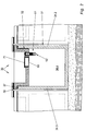
- einen vergrössert dargestellten Ausschnitt aus Fig. 1 im Bereich der Luftaustauschleitung;
- Fig. 6
- einen vergrössert dargestellten Ausschnitt aus Fig. 1 im Bereich der Entwässerungsleitung;
- Fig. 7
- einen vergrössert dargestellten Ausschnitt aus Fig. 2 im Bereich der Entwässerungsleitung;
- Fig. 8
- einen ausschnittsweise dargestellten Längsschnitt einer ersten Abwandlung der Bodenwanne nach Fig. 1;
- Fig. 9
- einen ausschnittsweise dargestellten Längsschnitt einer zweiten Abwandlung der Bodenwanne nach Fig. 1;
- Fig. 10
- einen vergrößert dargestellten Ausschnitt aus Fig. 9.
- Fig. 1
- A longitudinal section of a burial chamber with a trough and a trough as well as with an air exchange line and a drainage line;
- Fig. 2
- a cross-section of the burial chamber of Figure 1 with an assembly opening near the drainage line.
- Fig. 3
- an end view of the burial chamber of Figures 1 + 2 on the side of the air exchange line.
- Fig. 4
- a plan view of the burial chamber according to FIGS. 1-3;
- Fig. 5
- an enlarged section of Figure 1 in the area of the air exchange line.
- Fig. 6
- an enlarged section of Figure 1 in the area of the drainage line.
- Fig. 7
- an enlarged section of Figure 2 in the area of the drainage line.
- Fig. 8
- a fragmentary longitudinal section of a first modification of the floor pan of FIG. 1;
- Fig. 9
- a fragmentary longitudinal section of a second modification of the floor pan of FIG. 1;
- Fig. 10
- 9 shows an enlarged section from FIG. 9.
Die insbesondere aus Fig. 1 und Fig. 2 ersichtliche Grabkammer
30 weist als Hauptbaugruppen einen wannenförmigen
Grundkörper 31 und eine Abdeckung in Form eines Troges 32
auf. Der wannenförmige Grundkörper wird im folgenen kurz als
Bodenwanne 31 bezeichnet.The burial chamber which can be seen in particular from FIGS. 1 and 2
30 has a trough-shaped as main
Die Bodenwanne 31 wird durch einen Boden 33 und durch vier
Seitenwände oder Umfangswände 34 gebildet, die gas- und
wasserdicht aneinander anschließen. Bei Bedarf werden im
folgenden die vier Umfangswände 34 durch Zusatzziffern von
einander unterschieden. An der Oberseite 35 der Umfangswände
34 ist eine umlaufende Rinne 36 (Fig. 4) vorhanden, in
die ein ringförmig in sich geschlossenes Dichtungsband 37
eingelegt ist.The
Der Trog 32 wird durch einen Boden 38 und durch vier Seitenwände
oder Umfangswände 39 gebildet, die gas- und wasserdicht
aneinander anschließen. Auch hier werden bei Bedarf
die Umfangswände 39 durch Zusatzziffern voneinander unterschieden.The
Am oberen Rand der Umfangswände 39 des Troges 32 schließt
ringsum ein nach außen auskragender Rand 41 an der im
folgenden kurz als Kragrand 41 bezeichnet wird.Closes at the upper edge of the
Die Umfangswände 39 des Troges 32 haben einen Grundriss, der
innerhalb des Grundrisses der Umfangswände 34 der Bodenwanne
31 gelegen ist. Der Kragrand 41 überdeckt den Grundrissbereich
der Umfangswände 34 der Bodenwanne 31. Zweckmässigerweise
ist die Außenseite des Kragrandes 41 bündig mit
der Außenseite der Umfangswände 34 der Bodenwanne 31. Durch
diese Gestaltung des Troges 32 kann er in die Bodenwanne 31
eingehängt werden, wobei er mit seinem Kragrand 41 auf den
Umfangswänden 34 der Bodenwanne 31 aufliegt.The
Nach einer Belegung der Grabkammer 30 wird vor dem Einhängen
des Troges 32 das Dichtungsband 37 in die Rinne 36 der
Umfangswände 34 der Bodenwanne 31 einglegt. Dadurch wird das
Dichtungsband 37 zwischen dem Kragrand 41 und der Oberseite
der Umfangswände 34 der Bodenwanne eingespannt und so eine
hermetische Abdichtung zwischen Bodenwanne 31 und Trog 32
errreicht.After the
Die Bodenwanne 31 und der Trog 32 sind aus Beton hergestellt,
und zwar vorzugsweise aus Stahlfaser-Beton. The
Die Grabkammer 30 ist mit einer Luftaustauschleitung 42 ausgerüstet
(Fig. 1, 3 und 4) Dafür ist in einer der Umfangswände
34 der Bodenwanne 31, bei dem dargestellten Ausführungsbeispiel
in der Umfangswand 34.1, ein Durchgangsloch 43
vorhanden. Dieses ist soweit wie möglich oberhalb des
Bodens 33 angeordnet. Wie aus Fig. 5 näher zu ersehen ist,
ist das Durchgangsloch 43 mit einer Muffe 43 versehen. Diese
ist aus Kunststoff hergestellt. Ihre Länge ist zumindest
annähernd gleich der Wanddicke der Umfangswand 34.1. Die
Muffe 44 weist auf ihrer Innenseite zwei umlaufende
Rillen 45 auf, in die je ein Dichtungsring 46 in Form eines
Rundschnurringes eingesetzt ist. Wegen dieser zwei Dichtungsringe
46 wird die Muffe 44 auch als Doppelmuffe
bezeichnet. Die Muffe 43 wird bei der Herstellung der Bodenwanne
31 in deren Werkstoff eingebettet. Aufgrund der durch
die Rillen 45 entstandenen umlaufenden Ausbuchtungen an der
Aussenseite der Muffe 44 hat diese im Werkstoff der Umfangswand
34.1 eine ausreichende Haftung. Wenn es dennoch
wünschenswert oder erforderlich erscheint, kann die Muffe 44
zusätzlich mit einer Dichtungsmasse gegenüber der Umfangswand
34.1 abgedichtet werden.The
An das Durchgangsloch 43, genaugenommen an die Muffe 44,
schliesst die eigentliche Luftaustauschleitung 42 an. Diese
weist einen Rohrkrümmer von zumindest annähernd 90° aus. Der
Schenkel mit dem glatten Rohrabschnitt ist in die Muffe 44
eingesteckt, wo er von den beiden Dichtungsringen 46 festgehalten
und gleichzeitig abgedichtet wird. Der andere
Schenkel ist am Ende als Rohrmuffe ausgebildet, in die ein
Dichtungsring eingesetzt ist. In diese Rohrmuffe ist ein
gerader Rohrabschnitt eingesetzt.To the through
Am Ende dieses Rohrabschnittes ist ein Rückschlagventil 49
in Form eines Schwimmerventils angeschlossen, das bei außen
ansteigendem Wasser die Luftaustauschleitung 42 verschließt
und so verhindert, dass Wasser in den Innenraum der Grabkammer
30 eindringt. Die Teile der Luftaustaschleitung 42,
nämlich der Rohrkrümmer 47, der Rohrabschnitt 48 und das
Rückschlagventil 49, werden zusätzlich mittels eines Klebemittels
dauerhaft miteinander verbunden. Damit soll sichergestellt
werden, dass beim Auffüllen der Umgebung der Grabkammer
die Teile der Luftaustauschleitung 42 von einander
getrennt werden.At the end of this pipe section there is a
Die Luftaustauschleitung 42 erstreckt sich von dem Durchgangsloch
43 aus abwärts, wie aus Fig. 3 ersichtlich ist.
Eine leichte Schrägstellung kann ebenfalls zugelassen
werden. Wichtig ist, dass die Mündung der Luftaustauschleitung
42 so tief angeordnet ist, dass die Höhe des die
Luftaustauschleitung umhüllenden Auffüllmaterials und das
bis zur Erdoberfläche aufgebrachte Material eine ausreichende
biologische Reinigungswirkung in Bezug auf die
Verwesungsgase hat, die aus der Luftaustauschleitung austreten,
wenn bei Luftdruckschwankungen der Luftdruck außerhalb
der Grabkammer 30 niedriger als der Luftdurck innerhalb
der Grabkammer ist.The
Da der Trog 32 sich innerhalb der Umfangswände 34 der Bodenwanne
31 befindet, ist die Grabkammer 30 mit einer Entwässerungsleitung
51 (Fig. 1, 6 und 7) ausgerüstet, damit
das vom Trog 32aufgefangene Regen- und Schmelzwasser, aber
auch überschüssiges Gießwasser im Trog 32 sich nicht bis zu
seinem oberen Rand anstaut sondern nach außen abfließen
kann.Since the
Die Entwässerungsleitung 51 weist einen biegsamen
Schlauch 52 auf, der an jedem seiner Enden mit einer
Schlauchtülle 52 dauerhaft und dicht verbunden ist. Der
Schlauch 52 kann als glatter Schlauchh, als Wellschlauch
oder als Wendelschlauch ausgebildet sein. Als Wellschlauch
und als Wendelschlauch lässt er sich im allgemeinen leichter
biegen und auch in gewissen Grenzen in der Länge verändern.
Die Schlauchtüllen 53 sind Abschnitte eines starren zylindrischen
Rohres aus Kunststoff. The
Die Entwässerungsleitung 51 schliesst auf einer Seite an ein
Durchgangsloch 54 im Boden 38 des Rohres 32 und andererseits
an ein Durchgangsloch 55 in der Umfangswand 34 der Bodenwanne
31 an.The
Im Durchgangsloch 54 ist eine Doppelmuffe 56 angeordent, die
eine Länge hat, die gleich der Wanddicke des Bodens 38 ist,
und die bei der Herstellung des Troges 32 in dessen Werkstoff
eingebettet wird. Die Doppelmuffe 56 weist zwei umlaufende
Rillen auf, in die je ein Dichtungsring 57 in Form
eines Rundschnurringes eingesetzt ist.In the through
Die mit der Doppelmuffe 56 im Boden 38 des Troges 32 zusammenwirkende
Schlauchtülle 53.1 des Schlauches 52 ist nur bis
etwa zur Mitte der Doppelmuffe 56 in diese eingesteckt, so
dass sie nur mit dem unteren Dichtungsring 57 zusammenwirkt
und von diesem durch Reibschluss festgehalten wird. In den
oberen Teil der Doppelmuffe 56 ist ein Sieb 58 eingesteckt,
wie es zum Beispiel bei den Entwässerungsleitungen von
Flachdächern üblich ist.The cooperating with the
Im Durchgangsloch 55 in der Umfangswand 34 der Bodenwanne 31
ist ebenfalls eine Doppelmuffe in deren Werkstoff eingebettet.
Sie weist ebenfalls zwei Dichtungsringe 62 auf. Die
damit zusammenwirkende Schlauchhülle 53.2 des Schlauches 52
ist so lang ausgebildet, dass sie aus der Doppelmuffe 61
eine gewisse Strecke heraus ragt, damit das aus ihr austretende
Wasser nicht an der Außenseite der Umfangswand 34
herunter läuft, sondern gleich in das die Umfangswanne 34
umgebende Auffüllmaterial übertritt und von diesem abgeleitet
wird.In the through
Wie aus Fig. 2, 4 und 7 zu ersehen ist, ist in der Nachbarschaft
des Durchgangsloches 54 für die Entwässerungsleitung
51 im Boden 38 des Troges 32 eine Montageöffnung 65
vorhanden. As can be seen from Figs. 2, 4 and 7, is in the neighborhood
of the through
Die Montageöffnung 31 ist mit einer Doppelmuffe 66 versehen,
die im Werkstoff des Bodens 38 eingebettet ist. Sie weist
zwei Dichtungsringe 67 auf. Die Muffe 66 ist so angeordnet,
dass sie mit der Unterseite 68 des Bodens bündig ist und
über die Oberseite 69 um ein gewisses Maß übersteht. Die
Montageöffnung 65 wird mittels eines Deckels 71 verschlossen,
der einen hohlzylindrischen Kragen 72 aufweist,
der auf die Doppelmuffe 66 und ihre Dichtungsringe 67 abgestimmt
ist. Der Deckel 71 hat einen Aussendurchmesser der
größer als der Aussendurchmesser der Doppelmuffe 66 ist.
Das Übermass sollte so groß sein, dass der Deckel 71 bequem
mit den Händen erfasst werden kann und herausgehoben werden
kann. Darauf sollte auch der Überstand der Doppelmuffe über
die Oberseite 69 des Bodens 38 abgestimmt sein. Die Montageöffnung
65 wird zweckmäßigerweise so groß gewählt, dass
durch sie hindurch die Entwässerungsleitung 51, insbesondere
deren Schlauch 52, mit der Hand bequem erreicht werden kann-The mounting
An der Bodenwanne 31 sind auf der Au0enseite einer ihrer
Strirnwände in der Nähe deren oberen Randes mehrere Dübellöcher
75 vorhanden, in die Dübel eingesetzt sind. Darin
sind Befestigungsschrauben 76 eingeschraubt. die ein quader-förmiges
Grabmalfundament 77 mit der Bodenwanne 31 verbinden.
Darauf ist ein Grabmal 78 aufgesetzt und in der
üblichen Weise mit dem Grabmalfundament verbunden.On the
Aus Fig. 8 und 9 sind Abwandlungen der Grabkammer 30, und
zwar ihrer Bodenwanne, zu ersehen. Soweit im Folgenden
einzelne Baugruppen oder Bauteile nicht gesondert erläutert
werden, ist davon auszugehen, dass sie gleich oder zumindest
ähnlich den entsprechenden Baugruppen beziehungsweise Bauteilen
der Grabkammer 30 ausgebildet sind.8 and 9 are modifications of the
Die aus Fig. 8 ausschnittweise ersichtliche Bodenwanne 81
weist in ihrem Boden 82 ein Rückschlagventil 83 in Form
eines Schwimmerventils auf, wie es ähnlich in der Luftaustauschleitung
42 (Fig. 5) verwendet wird. Das Rückschlagventil
83 ist entweder, wie dargestellt, in den Werkstoff
des Bodens 82 eingebettet, oder es ist in ein nicht dargestelltes
Gehäuse wasserdicht eingesetzt, das seinerseits in
den Werkstoff des Bodens 82 eingebettet ist und/oder mittels
einer Dichtungsmasse mit ihm dicht vergossen ist.The
Das Rückschlagventil 83 ist zweckmäßigerweise mit einem
Kragen 84 versehen, soweit ein solcher nicht bereits durch
die Bauart des Rückschlagventils 83 vorhanden ist. Dieser
Kragen 84 ragt über die Oberseite 85 des Bodens 82 so hoch
hinaus, so hoch ein Flüssigkeitsspiegel in der Grabkammer 80
erwünscht ist, damit in der Grabkammer 80 stets eine für die
Verwesungsvorgänge in der Grabkammer ausreichende Luftfeuchtigkeit
gewährleistet ist.The
Bei der aus Fig. 9 ersichtlichen Grabkammer 90 mit der
Bodenwanne 91 und dem Trog 92 ist im Boden 93 der Bodenwanne
91 ein Durchgangsloch vorhanden, das mit einer Doppelmuffe
94 versehen ist. In die Doppelmuffe 94 ist ein Verschlusskörper
95 eingesetzt, der ähnlich dem Deckel 71 der
Montageöffnung 65 im Trog 92 gestaltet ist. Die Doppelmuffe
94 und der Deckel 95 haben jedoch kleinere Durchmessermaße.In the
Das Durchgangsloch mit der Doppelmuffe 94 und dem Deckel 95
ist zweckmäßigerweise im Grundrissbereich der Montageöffnung
65 im Trog 92 angeordnet, so dass der Verschlusskörper
95 von dort aus betätigt werden kann. Zu diesem Zweck
ist der Verschlusskörper 95 mit einem Koppelungselement 96
versehen, das zum Beispiel als ringförmiger Bügel an der
Oberseite des Verschlusskörpers 95 angeformt ist.The through hole with the
Aus Fig. 10 ist eine besondere Ausgestaltung des Verschlusskörpers
95 ersichtlich. Bei ihm sind in dem hohlzylindrischen
Kragen 97 radial ausgerichtete Durchgangslöcher
vorhanden, die in einer normal zu Längsachse des Verschlusskörpers
95 ausgerichteten Ebene angeordnet sind, die in
axialer Richtung zwischen den beiden Dichtungsringen der
Doppelmuffe 94 gelegen ist. Es ist zweckmäßig, wenn diese
Durchgangslöcher 98 nahe dem oberen Dichtungsring der
Doppelmuffe 97 gelegen sind.10 shows a special embodiment of the
Aufgrund dieser Durchgangslöcher 98 im Kragen 97 muss der
Verschlusskörper nur soweit angehoben werden, dass die
Durchgangslöcher 98 oberhalb des oberen Dichtungsringes der
Doppelmuffe 94 stehen. Dann bereits kann in der Bodenwanne
91 vorhandene Flüssigkeit nach unten austreten, soweit
sie in der Bodenwanne 91 höher als der obere Rand der
Doppelmuffe 94 steht. Auch hier richtet sich die Höhe dieses
Überstandes der Doppelmuffe 94 über den Boden 93 danach, wie
hoch eine solche Flüssigkeit stehen soll. Falls das nur in
sehr geringem Maße oder überhaupt nicht erwünscht ist,
können in dem überstehenden Rand der Doppelmuffe 94 Durchgangslöcher
oder Schlitze angebracht werden, durch die die
Flüssigkeit sofort austreten kann, sobald die Durchgangslöcher
98 am Verschlusskörper 95 über den oberen Dichtungsring
der Doppelmuffe 94 hochgezogen worden sind. Because of these through
- 3030th
- GrabkammerBurial chamber
- 3131
- BodenwanneFloor pan
- 3232
- Trogtrough
- 3333
- Bodenground
- 3434
- UmfangswändePeripheral walls
- 3535
- OberseiteTop
- 3636
- RinneGutter
- 3737
- DichtungsbandSealing tape
- 3838
- Bodenground
- 3939
- UmfangswändePeripheral walls
- 4141
- KragrandCantilever
- 4242
- LuftaustauschleitungAir exchange line
- 4343
- DurchaanaslochThrough hole
- 4444
- Muffesleeve
- 4545
- RillenGrooves
- 4646
- DichtunasrinaeDichtunasrinae
- 4747
- RohrkrümmerPipe elbow
- 4848
- RohrabschnittPipe section
- 4949
- RückschlaaventilReturn valve
- 5151
- EntwässerungsleitungDrainage pipe
- 5252
- Schlauchtube
- 5353
- SchlauchtüllenHose nozzles
- 5454
- DurchgangslochThrough hole
- 5555
- DurchgangslochThrough hole
- 5656
- DoppelmuffeDouble sleeve
- 5757
- DichrunasrinaeDichrunasrinae
- 5858
- Siebscree
- 6161
- DoppelmuffeDouble sleeve
- 6262
- DichtunasrinaeDichtunasrinae
- 6565
- MontageöffnungAssembly opening
- 6666
- DoppelmuffeDouble sleeve
- 6767
- DichtunasrinaeDichtunasrinae
- 6868
- Unterseitebottom
- 6969
- OberseiteTop
- 7171
- Deckelcover
- 7272
- KranenCranes
- 7373
- Randedge
- 7474
- MuffenabschnittSleeve section
- 7575
- DübellöcherDowel holes
- 7676
- BefestigungsschraubenMounting screws
- 7777
- GrabmalfundamentTomb foundation
- 7878
- GrabmalTomb
- 8080
- GrabkammerBurial chamber
- 8181
- BodenwanneFloor pan
- 8282
- Bodenground
- 8383
- Rückschlagventilcheck valve
- 8484
- Kragencollar
- 8585
- Oberseite Top
- 9090
- GrabkammerBurial chamber
- 9191
- BodenwanneFloor pan
- 9292
- Trogtrough
- 9393
- Bodenground
- 9494
- DoppelmuffeDouble sleeve
- 9595
- VerschlusskörperClosure body
- 9696
- KoppelungselementCoupling element
- 9797
- Kragencollar
- 9898
- DurchgangslöcherThrough holes
Claims (11)
Applications Claiming Priority (2)
| Application Number | Priority Date | Filing Date | Title |
|---|---|---|---|
| DE1999153740 DE19953740B4 (en) | 1999-11-09 | 1999-11-09 | grave chamber |
| DE19953740 | 1999-11-09 |
Publications (2)
| Publication Number | Publication Date |
|---|---|
| EP1099809A2 true EP1099809A2 (en) | 2001-05-16 |
| EP1099809A3 EP1099809A3 (en) | 2003-01-15 |
Family
ID=7928338
Family Applications (1)
| Application Number | Title | Priority Date | Filing Date |
|---|---|---|---|
| EP00124145A Withdrawn EP1099809A3 (en) | 1999-11-09 | 2000-11-07 | Burial vault |
Country Status (2)
| Country | Link |
|---|---|
| EP (1) | EP1099809A3 (en) |
| DE (1) | DE19953740B4 (en) |
Cited By (1)
| Publication number | Priority date | Publication date | Assignee | Title |
|---|---|---|---|---|
| CN1827986B (en) * | 2006-01-26 | 2010-05-12 | 吴晓鸣 | Totally-enclosed centralized cemetery |
Families Citing this family (3)
| Publication number | Priority date | Publication date | Assignee | Title |
|---|---|---|---|---|
| DE102008031869A1 (en) | 2008-07-05 | 2010-01-07 | Werner Frey | Burial chamber has a sectional concrete construction with base plate, sides and top cover secured by interlocking edge profiles and adhesive |
| DE102008031867A1 (en) | 2008-07-05 | 2010-01-07 | Ackermann, Peter | Burial chamber has base plate with rectangular layout and has circulating rebated joint, whose rib is aligned to base plate |
| DE102008031866A1 (en) | 2008-07-05 | 2010-01-07 | Ackermann, Peter | Grave chamber, has air exchange device formed by continuous air exchange opening, whose longitudinal axis is inclined from inward to outward, where air exchange device is arranged in wall of base body |
Citations (2)
| Publication number | Priority date | Publication date | Assignee | Title |
|---|---|---|---|---|
| DE3537367A1 (en) | 1985-10-21 | 1987-04-23 | Gerhard Suckfuell | Burial chamber |
| DE4118408A1 (en) | 1991-06-05 | 1992-12-10 | Guenther Ackermann | Burial chambers formed of pre-cast sections - chambers are watertight and ventilated through cover trough to ensure decomposition |
Family Cites Families (5)
| Publication number | Priority date | Publication date | Assignee | Title |
|---|---|---|---|---|
| DE3035578A1 (en) * | 1980-09-20 | 1982-04-08 | Lambert 5401 Dieblich Schäfer | Hygienic prefab. concrete grave - has chamber adjoining initial burial chamber with insulating panel inside sealing cover |
| DE19613380C1 (en) * | 1996-04-03 | 1997-05-15 | Reinhard Martin | Tomb chamber ventilation system |
| DE29609187U1 (en) * | 1996-05-22 | 1996-08-14 | Suckfuell Gerhard | Burial chamber |
| DE29813992U1 (en) * | 1998-08-05 | 1998-10-29 | Aschenbrenner Harald | Reusable burial chamber |
| DE29820298U1 (en) * | 1998-11-16 | 1999-03-18 | Lammering Thomas Dipl Ing | Grave chamber system solution |
-
1999
- 1999-11-09 DE DE1999153740 patent/DE19953740B4/en not_active Expired - Fee Related
-
2000
- 2000-11-07 EP EP00124145A patent/EP1099809A3/en not_active Withdrawn
Patent Citations (2)
| Publication number | Priority date | Publication date | Assignee | Title |
|---|---|---|---|---|
| DE3537367A1 (en) | 1985-10-21 | 1987-04-23 | Gerhard Suckfuell | Burial chamber |
| DE4118408A1 (en) | 1991-06-05 | 1992-12-10 | Guenther Ackermann | Burial chambers formed of pre-cast sections - chambers are watertight and ventilated through cover trough to ensure decomposition |
Cited By (1)
| Publication number | Priority date | Publication date | Assignee | Title |
|---|---|---|---|---|
| CN1827986B (en) * | 2006-01-26 | 2010-05-12 | 吴晓鸣 | Totally-enclosed centralized cemetery |
Also Published As
| Publication number | Publication date |
|---|---|
| DE19953740A1 (en) | 2001-05-10 |
| EP1099809A3 (en) | 2003-01-15 |
| DE19953740B4 (en) | 2007-12-06 |
Similar Documents
| Publication | Publication Date | Title |
|---|---|---|
| DE202015105638U1 (en) | floor drain | |
| EP1099809A2 (en) | Burial vault | |
| DE102008047254B3 (en) | Irrigation system for use with control device for plants, and for use in apartments for watering of house plants, has storage vessel for absorption of liquid serving for irrigation, and piston, which is partly projected in storage vessel | |
| DE19633987C2 (en) | Distribution device for rainwater | |
| DE3934633C1 (en) | Collector for rain water - tank sealed at bottom and mounted coaxially in drainage pit | |
| EP1653012A2 (en) | Installation for infiltration | |
| DE102009053027A1 (en) | System for draining and/or retaining rain water in e.g. building roof, has intake pipe discharging into cavity or into bed and provided for supplying rain water, where bed is made from water-permeable material e.g. sand or gravel | |
| DE3333883A1 (en) | Tank for a sewage pumping station | |
| DE19910254C2 (en) | Waste water lifting station | |
| DE19655160C2 (en) | Prefabricated filter to purify rain water | |
| EP0657015B1 (en) | Chimney base | |
| EP0699255A1 (en) | Prefabricated stucture of ferroconcrete or a substitute material | |
| DE19610743C2 (en) | Soil filter for rain and waste water | |
| DE4118408A1 (en) | Burial chambers formed of pre-cast sections - chambers are watertight and ventilated through cover trough to ensure decomposition | |
| DE60022526T2 (en) | MODULAR DRAMAGE BLOCK | |
| DE19951194A1 (en) | Multi-purpose shaft, small sewage treatment plant and wastewater treatment process | |
| EP0808966B1 (en) | Burial crypt | |
| DE2748934A1 (en) | Irrigation system for plant containers - has profiled irrigation and drainage sections in lower part of vessels interconnected by unions | |
| DE20320107U1 (en) | Water supply device for potted plants | |
| DE19835426C2 (en) | Standpipe arrangement for a downpipe for rainwater use | |
| EP1958500B1 (en) | Device for watering plants in containers | |
| EP0372535B1 (en) | Process for establishing a measuring point for ground water, and device for carrying out this process | |
| EP0528124A1 (en) | Burial crypt | |
| EP1386536A2 (en) | Buriable shaft for a watering system | |
| DE4320761A1 (en) | Tank |
Legal Events
| Date | Code | Title | Description |
|---|---|---|---|
| PUAI | Public reference made under article 153(3) epc to a published international application that has entered the european phase |
Free format text: ORIGINAL CODE: 0009012 |
|
| AK | Designated contracting states |
Kind code of ref document: A2 Designated state(s): AT BE CH CY DE DK ES FI FR GB GR IE IT LI LU MC NL PT SE TR |
|
| AX | Request for extension of the european patent |
Free format text: AL;LT;LV;MK;RO;SI |
|
| PUAL | Search report despatched |
Free format text: ORIGINAL CODE: 0009013 |
|
| AK | Designated contracting states |
Kind code of ref document: A3 Designated state(s): AT BE CH CY DE DK ES FI FR GB GR IE IT LI LU MC NL PT SE TR |
|
| AX | Request for extension of the european patent |
Free format text: AL;LT;LV;MK;RO;SI |
|
| AKX | Designation fees paid |
Designated state(s): AT BE CH CY DE DK ES FI FR GB GR IE IT LI LU MC NL PT SE TR |
|
| STAA | Information on the status of an ep patent application or granted ep patent |
Free format text: STATUS: THE APPLICATION IS DEEMED TO BE WITHDRAWN |
|
| 18D | Application deemed to be withdrawn |
Effective date: 20030603 |