EP1099553A2 - Dispositif et procédé pour éviter des enroulements dans une machine d'impression rotative - Google Patents
Dispositif et procédé pour éviter des enroulements dans une machine d'impression rotative Download PDFInfo
- Publication number
- EP1099553A2 EP1099553A2 EP00122294A EP00122294A EP1099553A2 EP 1099553 A2 EP1099553 A2 EP 1099553A2 EP 00122294 A EP00122294 A EP 00122294A EP 00122294 A EP00122294 A EP 00122294A EP 1099553 A2 EP1099553 A2 EP 1099553A2
- Authority
- EP
- European Patent Office
- Prior art keywords
- web
- cylinder
- doctor blade
- fed rotary
- blanket
- Prior art date
- Legal status (The legal status is an assumption and is not a legal conclusion. Google has not performed a legal analysis and makes no representation as to the accuracy of the status listed.)
- Withdrawn
Links
Images


Classifications
-
- B—PERFORMING OPERATIONS; TRANSPORTING
- B41—PRINTING; LINING MACHINES; TYPEWRITERS; STAMPS
- B41F—PRINTING MACHINES OR PRESSES
- B41F33/00—Indicating, counting, warning, control or safety devices
- B41F33/18—Web break detection
-
- B—PERFORMING OPERATIONS; TRANSPORTING
- B41—PRINTING; LINING MACHINES; TYPEWRITERS; STAMPS
- B41P—INDEXING SCHEME RELATING TO PRINTING, LINING MACHINES, TYPEWRITERS, AND TO STAMPS
- B41P2233/00—Arrangements for the operation of printing presses
- B41P2233/20—Safety devices preventing damage
- B41P2233/22—Safety devices preventing damage by deviating the web in case of web break
Definitions
- the present invention relates to an apparatus and a method for prevention of winders of a torn web of material around a cylinder Web-fed rotary printing press according to the preamble of claims 1 and 14.
- a broken web can quickly wrap around the Blanket cylinders wrap and considerable damage and thus downtime cause.
- US 5,678,484 discloses a device for preventing winders for a Web rotary printing machine.
- This device is a separate unit behind a last printing unit and placed in front of a dryer and a web break sensor and rollers to receive and tension the torn web.
- the device described in this patent can also be used as a web catcher because it catches the web after a tear and thus a winder prevented around the blanket cylinder.
- Web catching devices generally have the disadvantage of being expensive and complicated are demanding electronics and maintenance and their reliability can be different.
- webbing devices can because of their Size usually only behind the last printing unit and not between the Printing units are placed and can therefore be in front of the last printing unit printing units before a web break or insufficient web tension protect.
- Web safety devices cannot normally be used on an upper web a two-web inline printing machine.
- US 4,676,159 discloses an integrated in a paper transport or guide roller Paper cutter.
- the Paper cutter in a retracted condition and affects the operation of the Transport or guide roller not. If a web break is found, the Paper cutter over the circumference of the roller into a cutting position moved so that the web can be cut.
- This device has the disadvantage that in the event of a malfunction thereof, the web during printing is cut. It may also be desirable not to shut the web in place cut at which this device cuts the web. It also has Device the disadvantage that it is not for a normal blanket or Plate cylinder, but only used on a separate transport or guide roller can be.
- EP 0 442 824 A2 discloses a blanket winder detector with a serrated edge, to cut the web, if the web should start, around the rubber blanket wrap.
- the web can be pushed against the serrated edge using a push rod become.
- This device is arranged separately from the printing units and has the Disadvantage that if the jagged edge cannot separate the web, the Blanket winder does. In addition, the web may not be desirable cut at the point where this device cuts the web.
- the object of the present invention is a simple and reliable device to create that for preventing winder in a web-fed rotary press serves.
- the present invention provides an apparatus for preventing winders which a sensor for detecting a web break in a web-fed rotary printing press and a doctor blade controlled by the sensor, the doctor blade a first Assumes position in which it is not in contact with the outer surface of a cylinder Printing press stands, and occupies a second position in which it is in contact with the The outer surface of the cylinder stands. This is during normal operation Doctor knife in its first position. If the sensor detects a web break the doctor blade is moved to its second position, in which it touches the outer surface of the cylinder is turned on, so that when the web starts, it turns around the cylinder wrap, this deflects away from the cylinder and thus prevents a winder.
- the device of the present invention enables reliable and light weight Prevent a winder using a component that is small enough to be next to everyone Printing unit can be placed within the printing press. Even if one If the web breaks within a printing unit, a winder can be avoided. It is furthermore advantageous that the web by the device according to the present invention is not cut.
- the doctor blade can be moved between its first and second position by a piston, which can be activated electrically, hydraulically or pneumatically. Also the doctor blade can be attached to one side of a rotary arm, the other Side of the arm is provided with two stops to prevent the arm from moving limit. Set screws can be provided for the respective stops, so that the first and second positions of the doctor blade can be fine-tuned. The Setting the second position can help damage the blanket too prevent.
- the device can advantageously in a web-fed offset printing press be used in which this with a rubber blanket cylinder, which is a rubber blanket contributes, cooperates. It is particularly advantageous if the device with a gapless rubber blanket is used, since then the doctor blade does not have a Gap must move what the doctor blade potentially, but not necessarily could damage. However, the device can also be used with blankets that have a gap.
- the device according to the invention is also particularly advantageous in High speed web-fed rotary printing machines, e.g. B. in with over 610 m / min. (2000 feet / min.) Running machines, usable.
- the doctor blade can preferably be made of plastic.
- the doctor blade can advantageously be exchangeable in a knife holder being held.
- the knife holder can comprise a first and a second strip, wherein the first bar is located on a side of the doctor blade away from the cylinder.
- the knife holder functions as a clamp, which is a replacement of the Doctor blade allows.
- the second bar can have a width that is almost over extends the entire width of the doctor blade to support the doctor blade when this contacts the cylinder.
- the first and second strips preferably consist of a hard material, e.g. B. made of metal or a hard polymer material.
- a third Bar of the knife holder can be provided as a support along an edge of the doctor knife be made of the same material as the first and second strips.
- the doctor blade preferably contacts the in its second position Blanket cylinder such that between the doctor blade and a tangent to The outer surface of the blanket cylinder forms an obtuse angle. That angle favors the deflection of the web after a crack.
- the doctor blade can advantageously be located downstream of the cylinder, d. H. be placed on one side of the cylinder where the web passes through a nip moved while the sensor is attached anywhere along the track can be.
- a doctor blade housing is preferably on the drive-side frame of a printing unit attached or integrated so that the housing is firmly connected to the frame.
- the present invention also provides a method for preventing a winder a web-fed rotary printing machine, which is characterized by the detection, namely the Detecting a web break and moving a doctor blade into a position to a cylinder of the web-fed rotary printing press. That way the broken web is deflected from the cylinder.
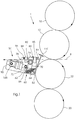
- a printing unit 1 is shown schematically Offset printing machine with an associated device 50 for preventing Winder.
- the printing unit 1 comprises an upper plate cylinder 10, an upper one Blanket cylinder 12, a lower blanket cylinder 22 and a lower one Plate cylinder 20.
- Fig. 1 shows an offset printing unit for two-sided printing of the web.
- the present invention may e.g. B. also in printing units for single-sided printing or used in non-offset printing units.
- the device for preventing winders comprises a doctor blade 52 which is fixed in a holder 60 is held, the rear bar 62, a front bar 64 and a Has bottom bar 66.
- the holder preferably functions as a clamp that the Doctor blade 52 clamps between the rear bar 62 and the front bar 64, the Rear bar 62 and the front bar 64 are movable with respect to each other, so that Doctor knife 52 can be easily removed and replaced.
- the holder 60 is on one side, namely on the holder side 72 of a rotatable Arms 70 attached or integrated therein, and the rotatable arm 70 is one fixed axis of rotation 78 rotatable.
- the parking stop 80 can be through the end of an adjustable screw 84, which in a shoulder 85th is adjustable, be formed.
- the extension 85 can be attached to a housing 90 of the device 50 attached or integrated into this.
- the housing 90 can with the frame of the Printing unit 1 connected or integrated into this.
- the stop stop 82 can be formed by an adjustable screw 86 which is adjustable in a shoulder 88.
- a piston 100 is rotatably connected at one end to one side of the arm 70, so that the piston 100 can move the arm 70 about the axis of rotation 78.
- the other end piston 100 is preferably rotatably attached to housing 90.
- the Piston 100 the arm 70 on its restricted side 74 between the Move the stop 80 and the stop 82.
- These two positions correspond to a parked position of the device 50, in which the doctor blade 52 um a gap 105 is separated from the lower blanket cylinder 22, as shown in FIG. 1 and an employed position, in which the doctor blade 52 the blanket cylinder 22nd contacted at a point 23, as shown in Fig. 2.
- the piston 100 can e.g. B. can be operated pneumatically, hydraulically or electrically. However, it is also possible use other activation devices.
- Fig. 3 is a schematic top view of the device of Fig. 1, but the Clarity shown without the stop and stop.
- the Doctor knife 52 is held in the holder 60 which in a free-floating arrangement is connected to or integrated in the rotatable arm 70.
- the axis of rotation 78 can be directly connected to the housing 90.
- a rotatable bolt 110 connects the Arm 70 with one end of the piston 100, the other end through one Bolt 112 is rotatably attached to the housing 90.
- the piston 100 can e.g. B. with a pneumatic, hydraulic or electrical power source.
- free floating arrangement can have the same set of activation elements on the other Side of the doctor blade 52 and holder 60 may be provided to provide additional support create.
- the doctor blade is 130 in length at least over half the length, preferably corresponds to the entire length of the assigned cylinder.
- Each printing unit has advantageously, but not necessarily an associated device 50, 150, 250, 350 for preventing winders.
- On Dryer 140 can be arranged behind the last printing unit 4.
- One or more web break sensors can be placed anywhere along the web be appropriate, the web break z. B. determine by loss of web tension can.
- the sensors can function on a photoelectric basis, e.g. B. using of laser and photo detector. However, they can also be contact sensors or on the Basis of other techniques, e.g. B. detect a web break using infrared rays.
- web break sensors 120, 121, 122, 123 and 124 are on provided at various points along the track.
- Each of the web break sensors is preferably 120, 121, 122, 123 and 124, e.g. B. electrically with a respective Activation mechanism for the doctor blades of devices 50, 150, 250 and 350 connected. All devices are of the same nature as that in 1, 2 and 3 described device 50. If one or several of the web break sensors 120, 121, 122, 123 or 124 detect a web break, all activation devices are activated, and the doctor blade of each The device moves from the parking position to the parking position, causing each Blanket in each printing unit is protected from a winder.
- the web follows one during normal production operation Path 8, with the path going through the gap between the top Blanket cylinder 12 and the lower blanket cylinder 22 is formed therethrough emotional. If a web break from a sensor z. B. due to lack of web tension are detected, the piston 100 is activated and this moves the doctor blade 52 in the contact with the rubber blanket 22 at a point 23, as shown in Fig. 2. If the web begins to wrap around cylinder 22 due to the web break, then follows the web an alternative path 9 away from the cylinder 22 so that a winder is avoided becomes. The machine can then be stopped and restarted as soon as the Web is tensioned again.
- the term "blanket cylinder" in this description can mean both namely a blanket cylinder body and the actual itself on the Blanket cylinder located blanket.
- the rubber blankets are the Printing unit gapless, removable rubber blankets, which axially on the respective Blanket cylinder body are applied.
- Such axially removable rubber blankets and the associated blanket cylinders are e.g. B. in U.S. Patent No. 5,429,048.
- the present invention can also be used for conventional, non-sleeve-shaped Blankets are used, provided that that used for the doctor blade Material is suitable and the dimension and type of between the ends of the flat Blanket shaped gap allow this.
- plate cylinder in this specification means any type Impression cylinder, e.g. B. a digitally imageable printing cylinder or a gapless Image carrier receiving printing cylinder, but preferably the plate cylinder a flat offset printing plate.
- web-fed rotary printing press in this description includes all Web-fed rotary printing presses of all sizes and types.
- the contact mentioned here with a cylinder means both physical contact and physical contact close proximity to the cylinder, d. H. less distance from the cylinder than the thickness of the used web material.
- doctor blade in this specification means any elongated Construction suitable to deflect the web from the cylinder when the former is in Contact with the cylinder.
- This construction includes e.g. B. both a thin narrow knife as well as thicker structures with a tapered or a U-shaped Edge.
Applications Claiming Priority (2)
| Application Number | Priority Date | Filing Date | Title |
|---|---|---|---|
| US43680999A | 1999-11-09 | 1999-11-09 | |
| US436809 | 1999-11-09 |
Publications (2)
| Publication Number | Publication Date |
|---|---|
| EP1099553A2 true EP1099553A2 (fr) | 2001-05-16 |
| EP1099553A3 EP1099553A3 (fr) | 2002-12-11 |
Family
ID=23733910
Family Applications (1)
| Application Number | Title | Priority Date | Filing Date |
|---|---|---|---|
| EP00122294A Withdrawn EP1099553A3 (fr) | 1999-11-09 | 2000-10-20 | Dispositif et procédé pour éviter des enroulements dans une machine d'impression rotative |
Country Status (3)
| Country | Link |
|---|---|
| EP (1) | EP1099553A3 (fr) |
| JP (1) | JP2001171077A (fr) |
| DE (1) | DE10052013A1 (fr) |
Families Citing this family (2)
| Publication number | Priority date | Publication date | Assignee | Title |
|---|---|---|---|---|
| DE102004017676B4 (de) * | 2004-04-10 | 2008-09-11 | Baldwin Germany Gmbh | Fehlererfassungsvorrichtung einer Rollenrotations-Druckmaschine |
| DE102015102695A1 (de) * | 2015-02-25 | 2016-08-25 | Manroland Web Systems Gmbh | Strangfangvorrichtung |
Citations (6)
| Publication number | Priority date | Publication date | Assignee | Title |
|---|---|---|---|---|
| EP0476437A1 (fr) * | 1990-09-15 | 1992-03-25 | Grafotec Kotterer Gmbh | Méthode et dispositif pour saisir une bande d'impression déchirée |
| EP0490106A1 (fr) * | 1990-12-07 | 1992-06-17 | M.A.N.-ROLAND Druckmaschinen Aktiengesellschaft | Dispositif pour éviter des dommages dans une presse d'imprimerie |
| US5429048A (en) * | 1989-10-05 | 1995-07-04 | Gaffney; John M. | Offset lithographic printing press |
| DE19508298A1 (de) * | 1995-03-09 | 1996-09-12 | Joh Clouth Fa | Schabvorrichtung für eine Walze |
| US5678484A (en) * | 1993-03-25 | 1997-10-21 | Baldwin Web Controls | Anti-wrap device for a web press |
| FR2761355A1 (fr) * | 1997-03-26 | 1998-10-02 | Heidelberg Harris Sa | Dispositif de retenue d'une bande dans la superstructure d'une machine rotative a imprimer |
-
2000
- 2000-10-20 EP EP00122294A patent/EP1099553A3/fr not_active Withdrawn
- 2000-10-20 DE DE2000152013 patent/DE10052013A1/de not_active Withdrawn
- 2000-11-06 JP JP2000337388A patent/JP2001171077A/ja active Pending
Patent Citations (6)
| Publication number | Priority date | Publication date | Assignee | Title |
|---|---|---|---|---|
| US5429048A (en) * | 1989-10-05 | 1995-07-04 | Gaffney; John M. | Offset lithographic printing press |
| EP0476437A1 (fr) * | 1990-09-15 | 1992-03-25 | Grafotec Kotterer Gmbh | Méthode et dispositif pour saisir une bande d'impression déchirée |
| EP0490106A1 (fr) * | 1990-12-07 | 1992-06-17 | M.A.N.-ROLAND Druckmaschinen Aktiengesellschaft | Dispositif pour éviter des dommages dans une presse d'imprimerie |
| US5678484A (en) * | 1993-03-25 | 1997-10-21 | Baldwin Web Controls | Anti-wrap device for a web press |
| DE19508298A1 (de) * | 1995-03-09 | 1996-09-12 | Joh Clouth Fa | Schabvorrichtung für eine Walze |
| FR2761355A1 (fr) * | 1997-03-26 | 1998-10-02 | Heidelberg Harris Sa | Dispositif de retenue d'une bande dans la superstructure d'une machine rotative a imprimer |
Also Published As
| Publication number | Publication date |
|---|---|
| JP2001171077A (ja) | 2001-06-26 |
| DE10052013A1 (de) | 2001-05-10 |
| EP1099553A3 (fr) | 2002-12-11 |
Similar Documents
| Publication | Publication Date | Title |
|---|---|---|
| DE2642381C3 (de) | Einrichtung zum registerhaltigen Zuführen einer Bahn | |
| DE3940796C2 (fr) | ||
| DE3215473C2 (de) | Vorrichtung zum Verhindern von Druckwerksschäden bei Druckträgerbahnrissen | |
| EP1127826B1 (fr) | Dispositif pour corriger la position latérale d'une bande de matériau imprimé dans une machine à imprimer rotative | |
| EP0119537A2 (fr) | Dispositif de capture d'une bande de papier | |
| DE4340858C2 (de) | Zylinder | |
| EP0187642B1 (fr) | Dispositif de sectionnement de la bande à imprimer dans une rotative d'impression à papier en bobines | |
| DE4410528A1 (de) | Druckmaschine mit Bahntrennvorrichtung | |
| EP1116560B1 (fr) | Dispofitif de coupe à longueur réglable | |
| EP0792814A1 (fr) | Machine de déballage de rouleaux, spécialement de rouleaux de papier d'imprimerie | |
| EP0110166B1 (fr) | Machine rotative d'impression de bandes | |
| EP1760019B1 (fr) | Dispositif de surveillance des ruptures de bande dans une machine rotative d'impression | |
| EP1110887B1 (fr) | Dispositif pour guider des feuilles et procédé appliquant ledit dispositif de guidage | |
| DE60110527T2 (de) | Führungseinrichtung zum Gebrauch in einem Falzapparat | |
| EP1099553A2 (fr) | Dispositif et procédé pour éviter des enroulements dans une machine d'impression rotative | |
| DE10159937B4 (de) | Rückhaltevorrichtung zum Klemmen einer in einer Rollenrotationsdruckmaschine laufenden Bedruckstoffbahn | |
| EP0986477B1 (fr) | Dispositif d'avance et de transfert d'une barre et procede d'avance et de transfert d'une barre d'enfilage | |
| DE10055586B4 (de) | Vorrichtung zum Erfassen flachen Materials auf einer Transportfläche | |
| EP0703077B1 (fr) | Dispositif pour éviter des dommages dans un presse d'imprimerie | |
| DE19709485C2 (de) | Verfahren zum abschnittweisen Schneiden einer Bedruckstoffbahn in Längsrichtung und Schneideinrichtung hierfür | |
| DE3911990C2 (fr) | ||
| CH634528A5 (en) | Web-fed rotary printing machine | |
| DE10040580A1 (de) | Vorrichtung zum Führen von Signaturen, insbesondere im Bereich eines Auslauf-Zwickels einer Schneidzylinderanordnung in einem Falzapparat einer Rotationsdruckmaschine | |
| EP1916211B1 (fr) | Dispositif attrapeur de feuilles automatique pour des presses rotatives à rouleaux | |
| EP3463891B1 (fr) | Dispositif et procédé pour nettoyer un cylindre de contre-pression central d'une machine d'impression flexographique |
Legal Events
| Date | Code | Title | Description |
|---|---|---|---|
| PUAI | Public reference made under article 153(3) epc to a published international application that has entered the european phase |
Free format text: ORIGINAL CODE: 0009012 |
|
| AK | Designated contracting states |
Kind code of ref document: A2 Designated state(s): AT BE CH CY DE DK ES FI FR GB GR IE IT LI LU MC NL PT SE |
|
| AX | Request for extension of the european patent |
Free format text: AL;LT;LV;MK;RO;SI |
|
| PUAL | Search report despatched |
Free format text: ORIGINAL CODE: 0009013 |
|
| AK | Designated contracting states |
Kind code of ref document: A3 Designated state(s): AT BE CH CY DE DK ES FI FR GB GR IE IT LI LU MC NL PT SE |
|
| AX | Request for extension of the european patent |
Free format text: AL;LT;LV;MK;RO;SI |
|
| AKX | Designation fees paid | ||
| REG | Reference to a national code |
Ref country code: DE Ref legal event code: 8566 |
|
| STAA | Information on the status of an ep patent application or granted ep patent |
Free format text: STATUS: THE APPLICATION IS DEEMED TO BE WITHDRAWN |
|
| 18D | Application deemed to be withdrawn |
Effective date: 20030612 |