EP1099553A2 - Device and method for avoiding winders in a rotary printing machine - Google Patents
Device and method for avoiding winders in a rotary printing machine Download PDFInfo
- Publication number
- EP1099553A2 EP1099553A2 EP00122294A EP00122294A EP1099553A2 EP 1099553 A2 EP1099553 A2 EP 1099553A2 EP 00122294 A EP00122294 A EP 00122294A EP 00122294 A EP00122294 A EP 00122294A EP 1099553 A2 EP1099553 A2 EP 1099553A2
- Authority
- EP
- European Patent Office
- Prior art keywords
- web
- cylinder
- doctor blade
- fed rotary
- blanket
- Prior art date
- Legal status (The legal status is an assumption and is not a legal conclusion. Google has not performed a legal analysis and makes no representation as to the accuracy of the status listed.)
- Withdrawn
Links
Images


Classifications
-
- B—PERFORMING OPERATIONS; TRANSPORTING
- B41—PRINTING; LINING MACHINES; TYPEWRITERS; STAMPS
- B41F—PRINTING MACHINES OR PRESSES
- B41F33/00—Indicating, counting, warning, control or safety devices
- B41F33/18—Web break detection
-
- B—PERFORMING OPERATIONS; TRANSPORTING
- B41—PRINTING; LINING MACHINES; TYPEWRITERS; STAMPS
- B41P—INDEXING SCHEME RELATING TO PRINTING, LINING MACHINES, TYPEWRITERS, AND TO STAMPS
- B41P2233/00—Arrangements for the operation of printing presses
- B41P2233/20—Safety devices preventing damage
- B41P2233/22—Safety devices preventing damage by deviating the web in case of web break
Definitions
- the present invention relates to an apparatus and a method for prevention of winders of a torn web of material around a cylinder Web-fed rotary printing press according to the preamble of claims 1 and 14.
- a broken web can quickly wrap around the Blanket cylinders wrap and considerable damage and thus downtime cause.
- US 5,678,484 discloses a device for preventing winders for a Web rotary printing machine.
- This device is a separate unit behind a last printing unit and placed in front of a dryer and a web break sensor and rollers to receive and tension the torn web.
- the device described in this patent can also be used as a web catcher because it catches the web after a tear and thus a winder prevented around the blanket cylinder.
- Web catching devices generally have the disadvantage of being expensive and complicated are demanding electronics and maintenance and their reliability can be different.
- webbing devices can because of their Size usually only behind the last printing unit and not between the Printing units are placed and can therefore be in front of the last printing unit printing units before a web break or insufficient web tension protect.
- Web safety devices cannot normally be used on an upper web a two-web inline printing machine.
- US 4,676,159 discloses an integrated in a paper transport or guide roller Paper cutter.
- the Paper cutter in a retracted condition and affects the operation of the Transport or guide roller not. If a web break is found, the Paper cutter over the circumference of the roller into a cutting position moved so that the web can be cut.
- This device has the disadvantage that in the event of a malfunction thereof, the web during printing is cut. It may also be desirable not to shut the web in place cut at which this device cuts the web. It also has Device the disadvantage that it is not for a normal blanket or Plate cylinder, but only used on a separate transport or guide roller can be.
- EP 0 442 824 A2 discloses a blanket winder detector with a serrated edge, to cut the web, if the web should start, around the rubber blanket wrap.
- the web can be pushed against the serrated edge using a push rod become.
- This device is arranged separately from the printing units and has the Disadvantage that if the jagged edge cannot separate the web, the Blanket winder does. In addition, the web may not be desirable cut at the point where this device cuts the web.
- the object of the present invention is a simple and reliable device to create that for preventing winder in a web-fed rotary press serves.
- the present invention provides an apparatus for preventing winders which a sensor for detecting a web break in a web-fed rotary printing press and a doctor blade controlled by the sensor, the doctor blade a first Assumes position in which it is not in contact with the outer surface of a cylinder Printing press stands, and occupies a second position in which it is in contact with the The outer surface of the cylinder stands. This is during normal operation Doctor knife in its first position. If the sensor detects a web break the doctor blade is moved to its second position, in which it touches the outer surface of the cylinder is turned on, so that when the web starts, it turns around the cylinder wrap, this deflects away from the cylinder and thus prevents a winder.
- the device of the present invention enables reliable and light weight Prevent a winder using a component that is small enough to be next to everyone Printing unit can be placed within the printing press. Even if one If the web breaks within a printing unit, a winder can be avoided. It is furthermore advantageous that the web by the device according to the present invention is not cut.
- the doctor blade can be moved between its first and second position by a piston, which can be activated electrically, hydraulically or pneumatically. Also the doctor blade can be attached to one side of a rotary arm, the other Side of the arm is provided with two stops to prevent the arm from moving limit. Set screws can be provided for the respective stops, so that the first and second positions of the doctor blade can be fine-tuned. The Setting the second position can help damage the blanket too prevent.
- the device can advantageously in a web-fed offset printing press be used in which this with a rubber blanket cylinder, which is a rubber blanket contributes, cooperates. It is particularly advantageous if the device with a gapless rubber blanket is used, since then the doctor blade does not have a Gap must move what the doctor blade potentially, but not necessarily could damage. However, the device can also be used with blankets that have a gap.
- the device according to the invention is also particularly advantageous in High speed web-fed rotary printing machines, e.g. B. in with over 610 m / min. (2000 feet / min.) Running machines, usable.
- the doctor blade can preferably be made of plastic.
- the doctor blade can advantageously be exchangeable in a knife holder being held.
- the knife holder can comprise a first and a second strip, wherein the first bar is located on a side of the doctor blade away from the cylinder.
- the knife holder functions as a clamp, which is a replacement of the Doctor blade allows.
- the second bar can have a width that is almost over extends the entire width of the doctor blade to support the doctor blade when this contacts the cylinder.
- the first and second strips preferably consist of a hard material, e.g. B. made of metal or a hard polymer material.
- a third Bar of the knife holder can be provided as a support along an edge of the doctor knife be made of the same material as the first and second strips.
- the doctor blade preferably contacts the in its second position Blanket cylinder such that between the doctor blade and a tangent to The outer surface of the blanket cylinder forms an obtuse angle. That angle favors the deflection of the web after a crack.
- the doctor blade can advantageously be located downstream of the cylinder, d. H. be placed on one side of the cylinder where the web passes through a nip moved while the sensor is attached anywhere along the track can be.
- a doctor blade housing is preferably on the drive-side frame of a printing unit attached or integrated so that the housing is firmly connected to the frame.
- the present invention also provides a method for preventing a winder a web-fed rotary printing machine, which is characterized by the detection, namely the Detecting a web break and moving a doctor blade into a position to a cylinder of the web-fed rotary printing press. That way the broken web is deflected from the cylinder.
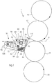
- a printing unit 1 is shown schematically Offset printing machine with an associated device 50 for preventing Winder.
- the printing unit 1 comprises an upper plate cylinder 10, an upper one Blanket cylinder 12, a lower blanket cylinder 22 and a lower one Plate cylinder 20.
- Fig. 1 shows an offset printing unit for two-sided printing of the web.
- the present invention may e.g. B. also in printing units for single-sided printing or used in non-offset printing units.
- the device for preventing winders comprises a doctor blade 52 which is fixed in a holder 60 is held, the rear bar 62, a front bar 64 and a Has bottom bar 66.
- the holder preferably functions as a clamp that the Doctor blade 52 clamps between the rear bar 62 and the front bar 64, the Rear bar 62 and the front bar 64 are movable with respect to each other, so that Doctor knife 52 can be easily removed and replaced.
- the holder 60 is on one side, namely on the holder side 72 of a rotatable Arms 70 attached or integrated therein, and the rotatable arm 70 is one fixed axis of rotation 78 rotatable.
- the parking stop 80 can be through the end of an adjustable screw 84, which in a shoulder 85th is adjustable, be formed.
- the extension 85 can be attached to a housing 90 of the device 50 attached or integrated into this.
- the housing 90 can with the frame of the Printing unit 1 connected or integrated into this.
- the stop stop 82 can be formed by an adjustable screw 86 which is adjustable in a shoulder 88.
- a piston 100 is rotatably connected at one end to one side of the arm 70, so that the piston 100 can move the arm 70 about the axis of rotation 78.
- the other end piston 100 is preferably rotatably attached to housing 90.
- the Piston 100 the arm 70 on its restricted side 74 between the Move the stop 80 and the stop 82.
- These two positions correspond to a parked position of the device 50, in which the doctor blade 52 um a gap 105 is separated from the lower blanket cylinder 22, as shown in FIG. 1 and an employed position, in which the doctor blade 52 the blanket cylinder 22nd contacted at a point 23, as shown in Fig. 2.
- the piston 100 can e.g. B. can be operated pneumatically, hydraulically or electrically. However, it is also possible use other activation devices.
- Fig. 3 is a schematic top view of the device of Fig. 1, but the Clarity shown without the stop and stop.
- the Doctor knife 52 is held in the holder 60 which in a free-floating arrangement is connected to or integrated in the rotatable arm 70.
- the axis of rotation 78 can be directly connected to the housing 90.
- a rotatable bolt 110 connects the Arm 70 with one end of the piston 100, the other end through one Bolt 112 is rotatably attached to the housing 90.
- the piston 100 can e.g. B. with a pneumatic, hydraulic or electrical power source.
- free floating arrangement can have the same set of activation elements on the other Side of the doctor blade 52 and holder 60 may be provided to provide additional support create.
- the doctor blade is 130 in length at least over half the length, preferably corresponds to the entire length of the assigned cylinder.
- Each printing unit has advantageously, but not necessarily an associated device 50, 150, 250, 350 for preventing winders.
- On Dryer 140 can be arranged behind the last printing unit 4.
- One or more web break sensors can be placed anywhere along the web be appropriate, the web break z. B. determine by loss of web tension can.
- the sensors can function on a photoelectric basis, e.g. B. using of laser and photo detector. However, they can also be contact sensors or on the Basis of other techniques, e.g. B. detect a web break using infrared rays.
- web break sensors 120, 121, 122, 123 and 124 are on provided at various points along the track.
- Each of the web break sensors is preferably 120, 121, 122, 123 and 124, e.g. B. electrically with a respective Activation mechanism for the doctor blades of devices 50, 150, 250 and 350 connected. All devices are of the same nature as that in 1, 2 and 3 described device 50. If one or several of the web break sensors 120, 121, 122, 123 or 124 detect a web break, all activation devices are activated, and the doctor blade of each The device moves from the parking position to the parking position, causing each Blanket in each printing unit is protected from a winder.
- the web follows one during normal production operation Path 8, with the path going through the gap between the top Blanket cylinder 12 and the lower blanket cylinder 22 is formed therethrough emotional. If a web break from a sensor z. B. due to lack of web tension are detected, the piston 100 is activated and this moves the doctor blade 52 in the contact with the rubber blanket 22 at a point 23, as shown in Fig. 2. If the web begins to wrap around cylinder 22 due to the web break, then follows the web an alternative path 9 away from the cylinder 22 so that a winder is avoided becomes. The machine can then be stopped and restarted as soon as the Web is tensioned again.
- the term "blanket cylinder" in this description can mean both namely a blanket cylinder body and the actual itself on the Blanket cylinder located blanket.
- the rubber blankets are the Printing unit gapless, removable rubber blankets, which axially on the respective Blanket cylinder body are applied.
- Such axially removable rubber blankets and the associated blanket cylinders are e.g. B. in U.S. Patent No. 5,429,048.
- the present invention can also be used for conventional, non-sleeve-shaped Blankets are used, provided that that used for the doctor blade Material is suitable and the dimension and type of between the ends of the flat Blanket shaped gap allow this.
- plate cylinder in this specification means any type Impression cylinder, e.g. B. a digitally imageable printing cylinder or a gapless Image carrier receiving printing cylinder, but preferably the plate cylinder a flat offset printing plate.
- web-fed rotary printing press in this description includes all Web-fed rotary printing presses of all sizes and types.
- the contact mentioned here with a cylinder means both physical contact and physical contact close proximity to the cylinder, d. H. less distance from the cylinder than the thickness of the used web material.
- doctor blade in this specification means any elongated Construction suitable to deflect the web from the cylinder when the former is in Contact with the cylinder.
- This construction includes e.g. B. both a thin narrow knife as well as thicker structures with a tapered or a U-shaped Edge.
Landscapes
- Inking, Control Or Cleaning Of Printing Machines (AREA)
- Rotary Presses (AREA)
- Controlling Rewinding, Feeding, Winding, Or Abnormalities Of Webs (AREA)
Abstract
Description
Die vorliegende Erfindung betrifft eine Vorrichtung und ein Verfahren zum Verhindern
von Wicklern einer gerissenen Materialbahn um einen Zylinder einer
Rollenrotationsdruckmaschine, gemäß dem Oberbegriff von Anspruch 1 und 14.The present invention relates to an apparatus and a method for prevention
of winders of a torn web of material around a cylinder
Web-fed rotary printing press according to the preamble of
In Rollenrotationsdruckmaschinen werden kontinuierliche Materialbahnen, beispielsweise Papierbahnen bedruckt. In US 5,429,048 ist eine Rollenrotations-Offsetdruckmaschine mit einer Reihe von Druckwerken beschrieben, durch welche eine zu bedruckende Materialbahn läuft. Jedes der Druckwerke umfasst einen Plattenzylinder, einen Gummituchzylinder und einen Gegendruckzylinder, der ein zweiter Gummituchzylinder sein kann. Eine bebilderte Druckplatte ist auf dem Plattenzylinder befestigt und ein spaltloses, hülsenförmiges Gummituch ist auf den Gummituchzylinder aufgeschoben. Während des Druckens bewegt sich die Bahn zwischen dem Gummituchzylinder und dem Gegendruckzylinder und anschließend durch einen Trockner hindurch, bevor sie weiter verarbeitet wird.In web-fed rotary printing machines, continuous material webs, for example Printed paper webs. In US 5,429,048 is a web-fed rotary offset printing press described a number of printing units, through which a to be printed Material web is running. Each of the printing units comprises a plate cylinder, one Blanket cylinder and an impression cylinder, which is a second blanket cylinder can be. An illustrated printing plate is attached to the plate cylinder and a gapless, sleeve-shaped rubber blanket is pushed onto the blanket cylinder. During printing, the web moves between the blanket cylinder and the Impression cylinder and then through a dryer before proceeding is processed.
Beim Betrieb von Rollenrotationsdruckmaschinen kann es aufgrund von Unvollkommenheiten in der Bahn zu Bahnrissen kommen. Bevor dann die Druckmaschine gestoppt werden kann, hat sich die gerissene Bahn möglicherweise bereits um einen oder mehrere Zylinder gewickelt und somit einen sogenannten Wickler erzeugt. Wickler bedeuten enorme Maschinenstillstandszeiten und somit verlorene Produktionszeit, denn die auf den Zylinder gewickelte Bahn muss entfernt werden, was oft ein zeitraubender Vorgang ist. Außerdem kann ein Bahnriss in Rollenrotations-Offsetdruckmaschinen zur Beschädigung des Gummituchs und auch der Maschine selbst führen.When operating web-fed rotary printing presses, it can be due to Imperfections in the web lead to web breaks. Before the press can be stopped, the broken web may already have one or wrapped several cylinders and thus created a so-called winder. Winder mean enormous machine downtimes and thus lost production time, because the web wound on the cylinder must be removed, which is often a time consuming process Process is. A web break can also be used in web-fed rotary offset presses Damage the rubber blanket and the machine itself.
Insbesondere in Hochgeschwindigkeits-Rollenrotationsdruckmaschinen, die beispielsweise ca. 610 m (2000 ft) pro Minute drucken, kann sich eine gerissene Bahn schnell um den Gummituchzylinder wickeln und beträchtlichen Schaden und damit Stillstandszeit verursachen.Especially in high-speed web-fed rotary printing presses, for example printing about 610 m (2000 ft) per minute, a broken web can quickly wrap around the Blanket cylinders wrap and considerable damage and thus downtime cause.
US 5,678,484 offenbart eine Vorrichtung zur Verhinderung von Wicklern für eine Rollenrotationsdruckmaschine. Diese Vorrichtung ist eine separate Einheit, die hinter einem letzten Druckwerk und vor einem Trockner platziert ist und einen Bahnriss-Sensor und Walzen umfasst, um die gerissene Bahn aufzunehmen und zu spannen. Somit wird vermieden, dass sich die Bahn um den Gummituchzylinder des letzten Druckwerks wickelt. Die in diesem Patent beschriebene Vorrichtung kann auch als Bahnfänger bezeichnet werden, weil diese die Bahn nach einem Riss auffängt und somit einen Wickler um den Gummituchzylinder verhindert.US 5,678,484 discloses a device for preventing winders for a Web rotary printing machine. This device is a separate unit behind a last printing unit and placed in front of a dryer and a web break sensor and rollers to receive and tension the torn web. Thus avoided that the web wrapped around the blanket cylinder of the last printing unit wraps. The device described in this patent can also be used as a web catcher because it catches the web after a tear and thus a winder prevented around the blanket cylinder.
Bahnfangvorrichtungen haben im allgemeinen den Nachteil, dass sie teuer und kompliziert sind, anspruchsvolle Elektronik und Wartung erfordern und ihre Zuverlässigkeit unterschiedlich sein kann. Außerdem können solche Bahnfangvorrichtungen wegen ihrer Größe normalerweise nur hinter dem letzten Druckwerk und nicht zwischen den Druckwerken platziert werden und können somit die sich vor dem letzten Druckwerk befindlichen Druckwerke nicht vor einem Bahnbruch oder mangelnder Bahnspannung schützen. Bahnfangvorrichtungen können normalerweise auch nicht an einer oberen Bahn einer Zwei-Bahnen-Inline-Druckmaschine verwendet werden.Web catching devices generally have the disadvantage of being expensive and complicated are demanding electronics and maintenance and their reliability can be different. In addition, such webbing devices can because of their Size usually only behind the last printing unit and not between the Printing units are placed and can therefore be in front of the last printing unit printing units before a web break or insufficient web tension protect. Web safety devices cannot normally be used on an upper web a two-web inline printing machine.
US 4,676,159 offenbart eine in eine Papiertransport- oder Führungswalze integrierte Papierschneidvorrichtung. Während des normalen Druckbetriebs befindet sich die Papierschneidvorrichtung in einem eingefahrenen Zustand und beeinflusst den Betrieb der Transport- oder Führungswalze nicht. Wenn ein Bahnriss festgestellt ist, wird die Papierschneidvorrichtung über den Umfang der Walze hinaus in eine Schneidposition bewegt, so dass die Bahn geschnitten werden kann. Diese Vorrichtung hat den Nachteil, dass im Falle einer Fehlfunktion derselben die Bahn während des Druckbetriebs geschnitten wird. Auch kann es wünschenswert sein, die Bahn nicht an der Stelle zu schneiden, an welcher diese Vorrichtung die Bahn schneidet. Außerdem hat diese Vorrichtung den Nachteil, dass sie nicht für einen normalen Gummituch- oder Plattenzylinder, sondern nur auf einer separaten Transport- oder Führungswalze verwendet werden kann.US 4,676,159 discloses an integrated in a paper transport or guide roller Paper cutter. During normal printing, the Paper cutter in a retracted condition and affects the operation of the Transport or guide roller not. If a web break is found, the Paper cutter over the circumference of the roller into a cutting position moved so that the web can be cut. This device has the disadvantage that in the event of a malfunction thereof, the web during printing is cut. It may also be desirable not to shut the web in place cut at which this device cuts the web. It also has Device the disadvantage that it is not for a normal blanket or Plate cylinder, but only used on a separate transport or guide roller can be.
EP 0 442 824 A2 offenbart einen Gummituch-Wickler-Detektor mit einer gezackten Kante, um die Bahn zu schneiden, falls die Bahn beginnen sollte, sich um das Gummituch zu wickeln. Mittels einer Schiebestange kann die Bahn gegen die gezackte Kante geschoben werden. Diese Vorrichtung ist separat von den Druckwerken angeordnet und hat den Nachteil, dass, wenn die gezackte Kante die Bahn nicht trennen kann, sich der Gummituchwickler doch vollzieht. Außerdem kann es wünschenswert sein, die Bahn nicht an der Stelle zu schneiden, an welcher diese Vorrichtung die Bahn schneidet.EP 0 442 824 A2 discloses a blanket winder detector with a serrated edge, to cut the web, if the web should start, around the rubber blanket wrap. The web can be pushed against the serrated edge using a push rod become. This device is arranged separately from the printing units and has the Disadvantage that if the jagged edge cannot separate the web, the Blanket winder does. In addition, the web may not be desirable cut at the point where this device cuts the web.
Es ist die Aufgabe der vorliegenden Erfindung eine einfache und zuverlässige Vorrichtung zu schaffen, die zum Verhindern von Wicklern in einer Rollenrotationsdruckmaschine dient.The object of the present invention is a simple and reliable device to create that for preventing winder in a web-fed rotary press serves.
Die vorliegende Erfindung sieht eine Vorrichtung zum Verhindern von Wicklern vor, die einen Sensor zur Erfassung eines Bahnrisses in einer Rollenrotationsdruckmaschine und ein von dem Sensor gesteuertes Rakelmesser umfasst, wobei das Rakelmesser eine erste Position einnimmt, in der es nicht in Kontakt mit der Mantelfläche eines Zylinders der Druckmaschine steht, und eine zweite Position einnimmt, in der es in Kontakt mit der Mantelfläche des Zylinders steht. Während des normalen Betriebs befindet sich das Rakelmesser in seiner ersten Position. Wenn durch den Sensor ein Bahnriss festgestellt wird, wird das Rakelmesser in seine zweite Position bewegt, in der es an die Mantelfläche des Zylinders angestellt ist, so dass, wenn die Bahn beginnt, sich um den Zylinder zu wickeln, diese weg vom Zylinder abgelenkt und somit ein Wickler verhindert wird.The present invention provides an apparatus for preventing winders which a sensor for detecting a web break in a web-fed rotary printing press and a doctor blade controlled by the sensor, the doctor blade a first Assumes position in which it is not in contact with the outer surface of a cylinder Printing press stands, and occupies a second position in which it is in contact with the The outer surface of the cylinder stands. This is during normal operation Doctor knife in its first position. If the sensor detects a web break the doctor blade is moved to its second position, in which it touches the outer surface of the cylinder is turned on, so that when the web starts, it turns around the cylinder wrap, this deflects away from the cylinder and thus prevents a winder.
Die Vorrichtung der vorliegenden Erfindung ermöglicht ein zuverlässiges und leichtes Verhindern eines Wicklers mittels einer Komponente, die klein genug ist, um neben jedem Druckwerk innerhalb der Druckmaschine platziert werden zu können. Selbst wenn sich ein Bahnriss innerhalb eines Druckwerks ereignet, kann ein Wickler vermieden werden. Es ist weiterhin von Vorteil, dass durch die Vorrichtung gemäß vorliegender Erfindung die Bahn nicht geschnitten wird.The device of the present invention enables reliable and light weight Prevent a winder using a component that is small enough to be next to everyone Printing unit can be placed within the printing press. Even if one If the web breaks within a printing unit, a winder can be avoided. It is furthermore advantageous that the web by the device according to the present invention is not cut.
Das Rakelmesser kann zwischen seiner ersten und zweiten Position durch einen Kolben, der elektrisch, hydraulisch oder pneumatisch aktiviert werden kann, bewegt werden. Auch kann das Rakelmesser an der einen Seite eines Dreharms angebracht sein, wobei die andere Seite des Arms mit zwei Anschlägen versehen ist, um die Bewegung des Arms zu begrenzen. Für die jeweiligen Anschläge können Stellschrauben vorgesehen sein, so dass die erste und die zweite Position des Rakelmessers feineingestellt werden können. Die Einstellung der zweiten Position kann helfen, eine Beschädigung des Gummituchs zu verhindern.The doctor blade can be moved between its first and second position by a piston, which can be activated electrically, hydraulically or pneumatically. Also the doctor blade can be attached to one side of a rotary arm, the other Side of the arm is provided with two stops to prevent the arm from moving limit. Set screws can be provided for the respective stops, so that the first and second positions of the doctor blade can be fine-tuned. The Setting the second position can help damage the blanket too prevent.
Die Vorrichtung kann in vorteilhafter Weise in einer Rollenrotations-Offsetdruckmaschine eingesetzt werden, in welcher diese mit einem Gummituchzylinder, der ein Gummituch trägt, zusammenwirkt. Es ist besonders vorteilhaft, wenn die Vorrichtung mit einem spaltlosen Gummituch verwendet wird, da sich dann das Rakelmesser nicht über einen Spalt bewegen muss, was das Rakelmesser potentiell, jedoch nicht notwendigerweise beschädigen könnte. Jedoch die Vorrichtung kann auch mit Gummitüchern verwendet werden, die einen Spalt aufweisen.The device can advantageously in a web-fed offset printing press be used in which this with a rubber blanket cylinder, which is a rubber blanket contributes, cooperates. It is particularly advantageous if the device with a gapless rubber blanket is used, since then the doctor blade does not have a Gap must move what the doctor blade potentially, but not necessarily could damage. However, the device can also be used with blankets that have a gap.
Die erfindungsgemäße Vorrichtung ist auch in besonders vorteilhafter Weise in Hochgeschwindigkeits-Rollenrotationsdruckmaschinen, z. B. in mit über 610 m/min. (2000 feet/min.) laufenden Maschinen, verwendbar.The device according to the invention is also particularly advantageous in High speed web-fed rotary printing machines, e.g. B. in with over 610 m / min. (2000 feet / min.) Running machines, usable.
Das Rakelmesser kann vorzugsweise aus Kunststoff hergestellt sein.The doctor blade can preferably be made of plastic.
In vorteilhafter Weise kann das Rakelmesser auswechselbar in einem Messerhalter gehalten werden. Der Messerhalter kann eine erste und eine zweite Leiste umfassen, wobei sich die erste Leiste an einer vom Zylinder entfernten Seite des Rakelmessers befindet. Vorzugsweise funktioniert der Messerhalter als eine Klemme, die ein Auswechseln des Rakelmessers ermöglicht. Die zweite Leiste kann eine Breite haben, die sich nahezu über die gesamte Breite des Rakelmessers erstreckt, um das Rakelmesser zu stützen, wenn dieses den Zylinder kontaktiert. Die erste und zweite Leiste bestehen vorzugsweise aus einem harten Material, z. B. aus Metall oder einem harten Polymermaterial. Eine dritte Leiste des Messerhalters kann als Stütze entlang einer Kante des Rakelmessers vorgesehen sein und aus dem gleichen Material wie die erste und zweite Leiste bestehen.The doctor blade can advantageously be exchangeable in a knife holder being held. The knife holder can comprise a first and a second strip, wherein the first bar is located on a side of the doctor blade away from the cylinder. Preferably, the knife holder functions as a clamp, which is a replacement of the Doctor blade allows. The second bar can have a width that is almost over extends the entire width of the doctor blade to support the doctor blade when this contacts the cylinder. The first and second strips preferably consist of a hard material, e.g. B. made of metal or a hard polymer material. A third Bar of the knife holder can be provided as a support along an edge of the doctor knife be made of the same material as the first and second strips.
Das Rakelmesser kontaktiert in seiner zweiten Position vorzugsweise den Gummituchzylinder derart, dass sich zwischen dem Rakelmesser und einer Tangente zur Mantelfläche des Gummituchzylinders ein stumpfer Winkel bildet. Dieser Winkel begünstigt die Ablenkung der Bahn nach einem Riss.The doctor blade preferably contacts the in its second position Blanket cylinder such that between the doctor blade and a tangent to The outer surface of the blanket cylinder forms an obtuse angle. That angle favors the deflection of the web after a crack.
Das Rakelmesser kann sich in vorteilhafter Weise stromabwärts des Zylinders befinden, d. h. auf einer Seite des Zylinders platziert sein, wo sich die Bahn durch einen Walzenspalt bewegt hat, während der Sensor an einer beliebigen Stelle entlang der Bahn angebracht sein kann.The doctor blade can advantageously be located downstream of the cylinder, d. H. be placed on one side of the cylinder where the web passes through a nip moved while the sensor is attached anywhere along the track can be.
Ein Rakelmesser-Gehäuse ist vorzugsweise am antriebsseitigen Rahmen eines Druckwerks angebracht oder integriert, so dass das Gehäuse fest mit dem Rahmen verbunden ist.A doctor blade housing is preferably on the drive-side frame of a printing unit attached or integrated so that the housing is firmly connected to the frame.
Die vorliegende Erfindung sieht auch ein Verfahren zum Verhindern eines Wicklers in einer Rollenrotationsdruckmaschine vor, welches sich durch das Erfassen, nämlich das Feststellen eines Bahnrisses und das Bewegen eines Rakelmessers in eine Anstellposition an einen Zylinder der Rollenrotationsdruckmaschine auszeichnet. Auf diese Weise kann die gerissene Bahn vom Zylinder abgelenkt werden.The present invention also provides a method for preventing a winder a web-fed rotary printing machine, which is characterized by the detection, namely the Detecting a web break and moving a doctor blade into a position to a cylinder of the web-fed rotary printing press. That way the broken web is deflected from the cylinder.
Die Erfindung wird in der folgenden Beschreibung eines bevorzugten Ausführungsbeispiels im Zusammenhang mit den beigefügten, nachstehend aufgeführten Zeichnungen näher erläutert. The invention is preferred in the following description Embodiment in connection with the accompanying, listed below Drawings explained in more detail.
- Fig. 1Fig. 1
- eine Seitenansicht eines Druckwerks einer Rollenrotations-Offsetdruckmaschine und eine Ausführungsform einer Vorrichtung zum Verhindern eines Wicklers gemäß der vorliegenden Erfindung, wobei sich die Vorrichtung in einer abgestellten Position befindet;a side view of a printing unit of a web-fed rotary offset printing press and an embodiment of an apparatus for preventing a winder according to the present invention, wherein the device in one parked position;
- Fig. 2Fig. 2
- eine Ansicht gemäß Fig. 1, jedoch mit der Vorrichtung zum Verhindern eines Wicklers in einer angestellten Position;a view of FIG. 1, but with the device for preventing Winder in an employed position;
- Fig. 3Fig. 3
- eine Vorderansicht der in Fig. 1 gezeigten erfindungsgemäßen Ausführungsform, und zwar an dem antriebsseitigen Rahmen eines Druckwerks befestigt; und2 shows a front view of the embodiment according to the invention shown in FIG. 1, namely attached to the drive-side frame of a printing unit; and
- Fig. 4Fig. 4
- eine Vierfarben-Rollenrotations-Offsetdruckmaschine mit vier Druckwerken, wobei jedes Druckwerk eine zugeordnete Vorrichtung zum Verhindern eines Wicklers aufweist.a four-color web-fed offset printing press with four printing units, wherein each printing unit has an associated device for preventing Has winder.
Fig. 1 und 2 zeigen eine Seitenansicht einer bevorzugten Ausführungsform der
vorliegenden Erfindung. Schematisch dargestellt ist ein Druckwerk 1 einer
Offsetdruckmaschine mit einer zugeordneten Vorrichtung 50 zum Verhindern eines
Wicklers. Das Druckwerk 1 umfasst einen oberen Plattenzylinder 10, einen oberen
Gummituchzylinder 12, einen unteren Gummituchzylinder 22 und einen unteren
Plattenzylinder 20. Während des Druckbetriebs des Druckwerks 1 bewegt sich eine
Materialbahn, wie z. B. Papier, durch einen von dem oberen Gummituchzylinder 12 und
dem unteren Gummituchzylinder 22 gebildeten Spalt und folgt einem
Weiterbearbeitungspfad 8.1 and 2 show a side view of a preferred embodiment of the
present invention. A
Während des Druckbetriebs wird Farbe auf die Plattenzylinder 10 und 20 aufgetragen,
welche die Farbe in Entsprechung des zu druckenden Bildes auf die jeweiligen
Gummituchzylinder 12 und 22 übertragen wird. Das Bild wird dann auf die Bahn gedruckt,
während diese sich durch den Walzenspalt bewegt. Fig. 1 zeigt ein Offset-Druckwerk für
zweiseitiges Bedrucken der Bahn. Die Vorrichtung zum Verhindern von Wicklern der
vorliegenden Erfindung kann jedoch z. B. auch in Druckwerken für einseitiges Drucken
oder in Non-Offset-Druckwerken verwendet werden.During the printing operation, ink is applied to the
Die Vorrichtung zum Verhindern von Wicklern umfasst ein Rakelmesser 52, das fest in
einem Halter 60 gehalten wird, der eine Hinterleiste 62, eine Vorderleiste 64 und eine
Bodenleiste 66 aufweist. Der Halter funktioniert vorzugsweise als eine Klemme, die das
Rakelmesser 52 zwischen der Hinterleiste 62 und der Vorderleiste 64 klemmt, wobei die
Hinterleiste 62 und die Vorderleiste 64 bezüglich einander bewegbar sind, so dass das
Rakelmesser 52 mühelos entfernt und ersetzt werden kann.The device for preventing winders comprises a
Der Halter 60 ist auf der einen Seite, nämlich auf der Halterseite 72 eines drehbaren
Arms 70 befestigt oder in diesen integriert, und der drehbare Arm 70 ist um eine
feststehende Drehachse 78 drehbar. Auf seiner anderen, nämlich auf der
bewegungsbeschränkten Seite 74 des Arms 70 ist dieser zwischen einem Abstell-Anschlag
80 und einem Anstell-Anschlag 82 beschränkt bewegbar. Der Abstell-Anschlag
80 kann durch das Ende einer verstellbaren Schraube 84, die in einem Ansatz 85
verstellbar ist, gebildet sein. Der Ansatz 85 kann an einem Gehäuse 90 der Vorrichtung 50
befestigt oder in dieses integriert sein. Das Gehäuse 90 kann mit dem Rahmen des
Druckwerks 1 verbunden oder in dieses integriert sein. Der Anstell-Anschlag 82 kann
durch eine verstellbare Schraube 86, die in einem Ansatz 88 verstellbar ist, gebildet sein.The
Ein Kolben 100 ist an seinem einen Ende mit einer Seite des Arms 70 drehbar verbunden,
so dass der Kolben 100 den Arm 70 um die Drehachse 78 bewegen kann. Das andere Ende
des Kolbens 100 ist vorzugsweise an dem Gehäuse 90 drehbar angebracht. Somit kann der
Kolben 100 den Arm 70 auf seiner bewegungsbeschränkten Seite 74 zwischen dem
Abstell-Anschlag 80 und dem Anstell-Anschlag 82 bewegen. Diese zwei Positionen
entsprechen einer abgestellten Position der Vorrichtung 50, in der das Rakelmesser 52 um
einen Spalt 105 vom unteren Gummituchzylinder 22 getrennt ist, wie dies in Fig. 1 gezeigt
ist, und einer angestellten Position, in der das Rakelmesser 52 den Gummituchzylinder 22
an einer Stelle 23 kontaktiert, wie dies in Fig. 2 gezeigt ist. Der Kolben 100 kann, z. B.
pneumatisch, hydraulisch oder elektrisch betätigt werden. Es ist jedoch auch möglich,
andere Aktivierungsvorrichtungen einzusetzen.A
Fig. 3 ist eine schematische Draufsicht der Vorrichtung der Fig. 1, jedoch der
Übersichtlichkeit wegen ohne den Anstell- und Abstell-Anschlag dargestellt. Das
Rakelmesser 52 wird in dem Halter 60 gehalten, der in freischwebender Anordnung mit
dem drehbaren Arm 70 verbunden oder in diesen integriert ist. Die Drehachse 78 kann
unmittelbar mit dem Gehäuse 90 verbunden sein. Ein drehbarer Bolzen 110 verbindet den
Arm 70 mit dem einen Ende des Kolben 100, der mit seinem anderen Ende durch einen
Bolzen 112 an dem Gehäuse 90 drehbar befestigt ist. Der Kolben 100 kann z. B. mit einer
pneumatischen, hydraulischen oder elektrischen Kraftquelle verbunden sein. Anstelle der
freischwebenden Anordnung kann ein gleicher Satz Aktivierungselemente auf der anderen
Seite des Rakelmessers 52 und Halters 60 vorgesehen sein, um eine zusätzliche Stütze zu
schaffen.Fig. 3 is a schematic top view of the device of Fig. 1, but the
Clarity shown without the stop and stop. The
Das Rakelmesser ist von einer Länge 130, die mindestens über der Hälfte der Länge, vorzugsweise der gesamten Länge des zugeordneten Zylinders entspricht.The doctor blade is 130 in length at least over half the length, preferably corresponds to the entire length of the assigned cylinder.
Fig. 4 zeigt eine Vierfarben-Rollenrotations-Offsetdruckmaschine mit vier Druckwerken 1,
2, 3 und 4. Jedes Druckwerk besitzt in vorteilhafter Weise, jedoch nicht notwendigerweise
eine zugeordnete Vorrichtung 50, 150, 250, 350 zum Verhindern von Wicklern. Ein
Trockner 140 kann hinter dem letzten Druckwerk 4 angeordnet sein.4 shows a four-color web-fed rotary offset printing machine with four
Ein oder mehrere Bahnriss-Sensoren können an beliebiger Stelle entlang der Bahn angebracht sein, die einen Bahnriss z. B. durch Verlust an Bahnspannung feststellen können. Die Sensoren können auf fotoelektrischer Basis funktionieren, z. B. unter Einsatz von Laser und Fotodetektor. Sie können jedoch auch Kontakt-Sensoren sein oder auf der Basis anderer Techniken, z. B. unter Einsatz von Infrarotstrahlen einen Bahnriss erfassen.One or more web break sensors can be placed anywhere along the web be appropriate, the web break z. B. determine by loss of web tension can. The sensors can function on a photoelectric basis, e.g. B. using of laser and photo detector. However, they can also be contact sensors or on the Basis of other techniques, e.g. B. detect a web break using infrared rays.
Wie in Fig. 4 gezeigt ist, sind die Bahnriss-Sensoren 120, 121, 122, 123 und 124 an
verschiedenen Stellen entlang der Bahn vorgesehen. Vorzugsweise ist jeder der Bahnriss-Sensoren
120, 121, 122, 123 und 124, z. B. elektrisch mit einem jeweiligen
Aktivierungsmechanismus für die Rakelmesser der Vorrichtungen 50, 150, 250 und 350
verbunden. Alle Vorrichtungen sind von gleicher Beschaffenheit wie die im
Zusammenhang mit den Fig. 1, 2 und 3 beschriebene Vorrichtung 50. Falls einer oder
mehrere der Bahnriss-Sensoren 120, 121, 122, 123 oder 124 einen Bahnriss feststellen,
werden alle Aktivierungsvorrichtungen aktiviert, und das Rakelmesser einer jeden
Vorrichtung bewegt sich von der Abstell-Position in die Anstell-Position, wodurch jedes
Gummituch in jedem Druckwerk vor einem Wickler geschützt wird. Alternativ können
eine einzige oder weniger als alle Vorrichtungen zum Verhindern von Wicklern aktiviert
werden, je nach dem an welcher Stelle der Bahnrisses stattfindet, d. h. je nach dem welcher
der Sensoren den Bahnriss feststellt. Wenn z. B. nur vom Bahnriss-Sensor 124 am
Trockner ein Bahnriss festgestellt wird, dann können z. B. nur die Vorrichtung 350 oder
die Vorrichtungen 250 und 350 aktiviert werden.As shown in FIG. 4,
Wie in Fig. 1 gezeigt ist, folgt die Bahn während des normalen Fortdruckbetriebs einem
Pfad 8, wobei sich die Bahn durch den Spalt, der zwischen dem oberen
Gummituchzylinder 12 und dem unteren Gummituchzylinder 22 gebildet ist, hindurch
bewegt. Sollte von einem Sensor ein Bahnriss z. B. aufgrund mangelnder Bahnspannung
festgestellt werden, wird der Kolben 100 aktiviert und dieser bewegt das Rakelmesser 52 in
den Kontakt mit dem Gummituch 22 an einer Stelle 23, wie dies in Fig. 2 gezeigt ist. Falls
die Bahn beginnt, sich aufgrund des Bahnrisses um den Zylinder 22 zu wickeln, dann folgt
die Bahn einem alternativen Pfad 9 weg vom Zylinder 22, so dass ein Wickler vermieden
wird. Die Maschine kann dann gestoppt und schnell wieder angefahren werden, sobald die
Bahn erneut gespannt ist.As shown in Fig. 1, the web follows one during normal
Die Bezeichnung "Gummituchzylinder" in dieser Beschreibung kann beides bedeuten, nämlich einen Gummituchzylinderkörper und das eigentliche sich auf dem Gummituchzylinder befindliche Gummituch. Vorzugsweise sind die Gummitücher des Druckwerks spaltlose, abnehmbare Gummitücher, welche axial auf den jeweiligen Gummituchzylinderkörper aufgebracht werden. Solche axial abnehmbaren Gummitücher und die zugeordneten Gummituchzylinder sind z. B. in US-Patent No. 5,429,048 offenbart. The term "blanket cylinder" in this description can mean both namely a blanket cylinder body and the actual itself on the Blanket cylinder located blanket. Preferably, the rubber blankets are the Printing unit gapless, removable rubber blankets, which axially on the respective Blanket cylinder body are applied. Such axially removable rubber blankets and the associated blanket cylinders are e.g. B. in U.S. Patent No. 5,429,048.
Die vorliegende Erfindung kann auch für konventionelle, nicht hülsenförmige Gummitücher angewandt werden, vorausgesetzt, dass das für das Rakelmesser verwendete Material geeignet ist und die Dimension und Art des zwischen den Enden des flachen Gummituchs geformten Spalts dies zulassen.The present invention can also be used for conventional, non-sleeve-shaped Blankets are used, provided that that used for the doctor blade Material is suitable and the dimension and type of between the ends of the flat Blanket shaped gap allow this.
Die Bezeichnung "Plattenzylinder" in dieser Beschreibung bedeutet eine beliebige Art Druckzylinder, z. B. einen digital bebilderbaren Druckzylinder oder einen einen spaltlosen Bildträger aufnehmenden Druckzylinder, vorzugsweise nimmt der Plattenzylinder jedoch eine flache Offsetdruckplatte auf.The term "plate cylinder" in this specification means any type Impression cylinder, e.g. B. a digitally imageable printing cylinder or a gapless Image carrier receiving printing cylinder, but preferably the plate cylinder a flat offset printing plate.
Die Bezeichnung "Rollenrotationsdruckmaschine" in dieser Beschreibung umfasst alle Rollenrotationsdruckmaschinen jeglicher Größe und Art. Der hier erwähnte Kontakt mit einem Zylinder bedeutet sowohl den eigentlichen physischen Kontakt als auch die unmittelbare Nähe zum Zylinder, d. h. weniger Abstand vom Zylinder als die Dicke des verwendeten Bahnmaterials.The term "web-fed rotary printing press" in this description includes all Web-fed rotary printing presses of all sizes and types. The contact mentioned here with a cylinder means both physical contact and physical contact close proximity to the cylinder, d. H. less distance from the cylinder than the thickness of the used web material.
Die Bezeichnung "Rakelmesser" in dieser Beschreibung bedeutet eine beliebige längliche Konstruktion, die geeignet ist, um die Bahn vom Zylinder abzulenken, wenn sich erstere in Kontakt mit dem Zylinder befindet. Diese Konstruktion umfasst z. B. sowohl ein dünnes schmales Messer als auch dickere Strukturen mit einer spitz zulaufenden oder einer U-förmigen Kante. The term "doctor blade" in this specification means any elongated Construction suitable to deflect the web from the cylinder when the former is in Contact with the cylinder. This construction includes e.g. B. both a thin narrow knife as well as thicker structures with a tapered or a U-shaped Edge.
- 1, 2, 3, 41, 2, 3, 4
- DruckwerkePrinting units
- 88th
- Weiterbearbeitungspfad der BahnFurther processing path of the web
- 99
- alternativer Pfad der Bahnalternative path of the train
- 1010th
- oberer Plattenzylinderupper plate cylinder
- 1212th
- oberer Gummituchzylinderupper blanket cylinder
- 2020th
- unterer Plattenzylinderlower plate cylinder
- 2222
- unterer Gummituchzylinderlower blanket cylinder
- 2323
-
Kontaktstelle des Gummituchzylinders 22Contact point of the
blanket cylinder 22 - 5050
- Vorrichtung zum Verhindern von WicklernDevice for preventing winders
- 5252
- RakelmesserDoctor knife
- 6060
- Halterholder
- 6262
-
Hinterleiste des Halters 60Rear bar of the
holder 60 - 6464
-
Vorderleiste des Halters 60Front bar of the
holder 60 - 6666
-
Bodenleiste des Halters 60Base strip of the
holder 60 - 7070
- Armpoor
- 7272
-
Halterseite des Arms 70Holder side of
arm 70 - 7474
-
bewegungsbeschränkte Seite des Arms 70restricted side of
arm 70 - 7878
-
Drehachse des Arms 70
Arm 70 axis of rotation - 8080
- Abstell-AnschlagParking stop
- 8282
- Anstell-AnschlagPosition stop
- 8484
- verstellbare Schraube (Abstell-Anschlag)adjustable screw (stop)
- 8585
- Ansatzapproach
- 8686
- verstellbare Schraube (Anstell-Anschlag)adjustable screw (stop)
- 8888
- Ansatzapproach
- 9090
-
Gehäuse der Vorrichtung 50
Device housing 50 - 100100
- Kolbenpiston
- 105105
- Spaltgap
- 110110
- Bolzen bolt
- 112112
- Bolzenbolt
- 120120
-
Bahnriss-Sensor für die Vorrichtung 50Web break sensor for
device 50 - 121121
-
Bahnriss-Sensor für die Vorrichtung 150Web break sensor for
device 150 - 122122
-
Bahnriss-Sensor für die Vorrichtung 250Web break sensor for
device 250 - 123123
-
Bahnriss-Sensor für die Vorrichtung 350Web break sensor for
device 350 - 124124
-
Bahnriss-Sensor für den Trockner 140Web break sensor for
dryer 140 - 130130
- Länge des RakelmessersLength of the doctor blade
- 140140
- Trocknerdryer
- 150150
- Vorrichtung zum Verhindern von WicklernDevice for preventing winders
- 250250
- Vorrichtung zum Verhindern von WicklernDevice for preventing winders
- 350350
- Vorrichtung zum Verhindern von WicklernDevice for preventing winders
Claims (16)
einen Sensor (120, 121, 122, 123, 124) zum Erfassen eines Bahnrisses in der Rollenrotationsdruckmaschine; und
ein Rakelmesser (52), das von dem Sensor (120, 121, 122, 123, 124) gesteuert wird, wobei das Rakelmesser (52) im Normalbetrieb eine erste Position einnimmt, in der es von der Mantelfläche des Zylinders (22) abgestellt ist, und im Falle eines Bahnrisses eine zweite Position einnimmt, in der es an die Mantelfläche des Zylinders (22) angestellt ist.Device for preventing winders (50, 150, 250, 350) in a web-fed rotary printing press having a cylinder (22) with a lateral surface, characterized by
a sensor (120, 121, 122, 123, 124) for detecting a web break in the web-fed rotary printing press; and
a doctor blade (52) which is controlled by the sensor (120, 121, 122, 123, 124), the doctor blade (52) assuming a first position in normal operation, in which it is set down from the outer surface of the cylinder (22) , and in the event of a web break assumes a second position in which it is placed against the lateral surface of the cylinder (22).
dadurch gekennzeichnet,
dass ferner ein mit dem Rakelmesser verbundener Kolben (100) vorgesehen ist, der von dem Sensor (120, 121, 122, 123, 124) gesteuert wird und das Rakelmesser (52) zwischen seiner ersten und zweiten Position bewegt.Device according to claim 1,
characterized,
that there is also a piston (100) connected to the doctor blade, which is controlled by the sensor (120, 121, 122, 123, 124) and moves the doctor blade (52) between its first and second positions.
dadurch gekennzeichnet,
dass ferner ein drehbarer Arm (70) vorgesehen ist, der mit dem Rakelmesser (52) verbunden ist.Device according to claim 1 or 2,
characterized,
that a rotatable arm (70) is also provided, which is connected to the doctor blade (52).
dadurch gekennzeichnet,
dass die erste und die zweite Position des Rakelmessers (52) von einem Anstell-Anschlag (82) und einem Abstell-Anschlag (80) bestimmt sind, welche die Bewegung des Rakelmessers (52) beschränken. Device according to one of the preceding claims,
characterized,
that the first and the second position of the doctor blade (52) are determined by an attack stop (82) and a stop stop (80) which restrict the movement of the doctor knife (52).
dadurch gekennzeichnet,
dass der Anstell-Anschlag und der Abstell-Anschlag verstellbar sind.Device according to claim 4,
characterized,
that the stop and the stop are adjustable.
dadurch gekennzeichnet,
dass ferner ein Halter (60) für das Rakelmesser (52) vorgesehen ist.Device according to one of the preceding claims,
characterized,
that a holder (60) for the doctor blade (52) is also provided.
dadurch gekennzeichnet,
dass der Halter (60) als eine Klemme funktioniert.Device according to claim 6,
characterized,
that the holder (60) functions as a clamp.
dadurch gekennzeichnet,
dass die Länge des Rakelmessers (52) der Länge des Zylinders (22) entspricht.Device according to one of the preceding claims,
characterized,
that the length of the doctor blade (52) corresponds to the length of the cylinder (22).
dadurch gekennzeichnet,
dass das Rakelmesser (52) in seiner zweiten Position an die Mantelfläche des Gummituchzylinders (22) in einem stumpfen Winkel angestellt ist.Device according to one of the preceding claims,
characterized,
that the doctor blade (52) is in its second position against the outer surface of the blanket cylinder (22) at an obtuse angle.
gekennzeichnet durch
eine Vorrichtung nach einem der vorhergehenden Ansprüche.Web-fed rotary printing press with a first plate cylinder (20) and with a first blanket cylinder (22) having a lateral surface,
marked by
a device according to one of the preceding claims.
dadurch gekennzeichnet,
dass der erste Gummituchzylinder (22) ein spaltloses Gummituch umfasst, welches die Mantelfläche des Gummituchzylinders (22) bildet. Web-fed rotary offset printing machine according to claim 10,
characterized,
that the first blanket cylinder (22) comprises a gapless blanket which forms the outer surface of the blanket cylinder (22).
dadurch gekennzeichnet,
dass ferner ein zweiter Gummituchzylinder (12) vorgesehen ist, der mit dem ersten Gummituchzylinder (22) einen Spalt bildet, und dass die Vorrichtung zum Verhindern von Wicklern stromabwärts des Spalts angeordnet ist.Web-fed rotary offset printing machine according to claim 10 or 11,
characterized,
that a second blanket cylinder (12) is also provided, which forms a gap with the first blanket cylinder (22), and that the device for preventing winders is arranged downstream of the gap.
dadurch gekennzeichnet,
dass diese mindestens zwei Druckwerke (1, 2, 3, 4) umfasst, wobei jedes Druckwerk (1, 2, 3, 4) eine Vorrichtung zur Verhinderung von Wicklern (50, 150, 250, 350, 120, 121, 122, 123) aufweist.Web-fed rotary offset printing machine according to one of Claims 10 to 12,
characterized,
that it comprises at least two printing units (1, 2, 3, 4), each printing unit (1, 2, 3, 4) having a device for preventing winders (50, 150, 250, 350, 120, 121, 122, 123 ) having.
gekennzeichnet durch
folgende Verfahrensschritte:
marked by
following process steps:
welches ferner den Schritt des Ablenkens der Bahn weg vom Zylinder umfasst.The method of claim 14
which further comprises the step of deflecting the web away from the cylinder.
welches ferner den Schritt des Bedruckens der Bahn bei einer Geschwindigkeit von 610 m/min. (2000 ft/min.) oder mehr umfasst.A method according to claim 16,
which further includes the step of printing the web at a speed of 610 m / min. (2000 ft / min.) Or more.
Applications Claiming Priority (2)
| Application Number | Priority Date | Filing Date | Title |
|---|---|---|---|
| US436809 | 1995-05-05 | ||
| US43680999A | 1999-11-09 | 1999-11-09 |
Publications (2)
| Publication Number | Publication Date |
|---|---|
| EP1099553A2 true EP1099553A2 (en) | 2001-05-16 |
| EP1099553A3 EP1099553A3 (en) | 2002-12-11 |
Family
ID=23733910
Family Applications (1)
| Application Number | Title | Priority Date | Filing Date |
|---|---|---|---|
| EP00122294A Withdrawn EP1099553A3 (en) | 1999-11-09 | 2000-10-20 | Device and method for avoiding winders in a rotary printing machine |
Country Status (3)
| Country | Link |
|---|---|
| EP (1) | EP1099553A3 (en) |
| JP (1) | JP2001171077A (en) |
| DE (1) | DE10052013A1 (en) |
Families Citing this family (2)
| Publication number | Priority date | Publication date | Assignee | Title |
|---|---|---|---|---|
| DE102004017676B4 (en) * | 2004-04-10 | 2008-09-11 | Baldwin Germany Gmbh | Error detection device of a web-fed rotary printing press |
| DE102015102695A1 (en) * | 2015-02-25 | 2016-08-25 | Manroland Web Systems Gmbh | Train safety gear |
Citations (6)
| Publication number | Priority date | Publication date | Assignee | Title |
|---|---|---|---|---|
| EP0476437A1 (en) * | 1990-09-15 | 1992-03-25 | Grafotec Kotterer Gmbh | Method and device for seizing a broken printing web |
| EP0490106A1 (en) * | 1990-12-07 | 1992-06-17 | M.A.N.-ROLAND Druckmaschinen Aktiengesellschaft | Device for preventing damage in a printing machine |
| US5429048A (en) * | 1989-10-05 | 1995-07-04 | Gaffney; John M. | Offset lithographic printing press |
| DE19508298A1 (en) * | 1995-03-09 | 1996-09-12 | Joh Clouth Fa | Doctor blade for paper machine roll, used to prevent wind-up if the web breaks |
| US5678484A (en) * | 1993-03-25 | 1997-10-21 | Baldwin Web Controls | Anti-wrap device for a web press |
| FR2761355A1 (en) * | 1997-03-26 | 1998-10-02 | Heidelberg Harris Sa | Rotary printing press web holder |
-
2000
- 2000-10-20 EP EP00122294A patent/EP1099553A3/en not_active Withdrawn
- 2000-10-20 DE DE2000152013 patent/DE10052013A1/en not_active Withdrawn
- 2000-11-06 JP JP2000337388A patent/JP2001171077A/en active Pending
Patent Citations (6)
| Publication number | Priority date | Publication date | Assignee | Title |
|---|---|---|---|---|
| US5429048A (en) * | 1989-10-05 | 1995-07-04 | Gaffney; John M. | Offset lithographic printing press |
| EP0476437A1 (en) * | 1990-09-15 | 1992-03-25 | Grafotec Kotterer Gmbh | Method and device for seizing a broken printing web |
| EP0490106A1 (en) * | 1990-12-07 | 1992-06-17 | M.A.N.-ROLAND Druckmaschinen Aktiengesellschaft | Device for preventing damage in a printing machine |
| US5678484A (en) * | 1993-03-25 | 1997-10-21 | Baldwin Web Controls | Anti-wrap device for a web press |
| DE19508298A1 (en) * | 1995-03-09 | 1996-09-12 | Joh Clouth Fa | Doctor blade for paper machine roll, used to prevent wind-up if the web breaks |
| FR2761355A1 (en) * | 1997-03-26 | 1998-10-02 | Heidelberg Harris Sa | Rotary printing press web holder |
Also Published As
| Publication number | Publication date |
|---|---|
| EP1099553A3 (en) | 2002-12-11 |
| DE10052013A1 (en) | 2001-05-10 |
| JP2001171077A (en) | 2001-06-26 |
Similar Documents
| Publication | Publication Date | Title |
|---|---|---|
| DE2642381C3 (en) | Device for feeding a web in register | |
| DE3940796C2 (en) | ||
| DE3215473C2 (en) | Device for preventing printing unit damage in the event of print carrier web breaks | |
| EP1127826B1 (en) | Device for correcting the lateral position of a printed material web in a rotary printing machine | |
| EP0119537A2 (en) | Paper web catching device | |
| DE4340858C2 (en) | cylinder | |
| EP0187642B1 (en) | Web-severing device for a web-fed rotary printing press | |
| DE4410528A1 (en) | Printing machine with web cutting device | |
| EP1116560B1 (en) | Cutting device with adjustable cutting lenght | |
| EP0792814A1 (en) | Unpacking machines for rolls, especially printing paper rolls | |
| EP0110166B1 (en) | Rotary web printing machine | |
| EP1760019B1 (en) | Monitoring system for web breaks in a rotary printing press | |
| EP1110887B1 (en) | Device for guiding sheets and method for applying the guiding device | |
| DE60110527T2 (en) | Guiding device for use in a folder | |
| EP1099553A2 (en) | Device and method for avoiding winders in a rotary printing machine | |
| DE10159937B4 (en) | Retaining device for clamping a running in a web-fed printing press substrate | |
| EP0986477B1 (en) | Device for cutting off and conveying streaks and method for cutting off and transferring a threading streak | |
| DE10055586B4 (en) | Device for detecting flat material on a transport surface | |
| EP0703077B1 (en) | Device for preventing damage in a printing machine | |
| DE3911990C2 (en) | ||
| CH634528A5 (en) | Web-fed rotary printing machine | |
| DE10040580A1 (en) | Device for guiding signatures, in particular in the area of an outlet gusset of a cutting cylinder arrangement in a folder of a rotary printing press | |
| EP1916211B1 (en) | Automatic sheet gripping device for rotary printing presses | |
| EP3463891B1 (en) | Device and method for cleaning a central impression cylinder of a flexographic printing press | |
| EP0792813A1 (en) | Machine for unpacking rolls, especially printing paper rolls |
Legal Events
| Date | Code | Title | Description |
|---|---|---|---|
| PUAI | Public reference made under article 153(3) epc to a published international application that has entered the european phase |
Free format text: ORIGINAL CODE: 0009012 |
|
| AK | Designated contracting states |
Kind code of ref document: A2 Designated state(s): AT BE CH CY DE DK ES FI FR GB GR IE IT LI LU MC NL PT SE |
|
| AX | Request for extension of the european patent |
Free format text: AL;LT;LV;MK;RO;SI |
|
| PUAL | Search report despatched |
Free format text: ORIGINAL CODE: 0009013 |
|
| AK | Designated contracting states |
Kind code of ref document: A3 Designated state(s): AT BE CH CY DE DK ES FI FR GB GR IE IT LI LU MC NL PT SE |
|
| AX | Request for extension of the european patent |
Free format text: AL;LT;LV;MK;RO;SI |
|
| AKX | Designation fees paid | ||
| REG | Reference to a national code |
Ref country code: DE Ref legal event code: 8566 |
|
| STAA | Information on the status of an ep patent application or granted ep patent |
Free format text: STATUS: THE APPLICATION IS DEEMED TO BE WITHDRAWN |
|
| 18D | Application deemed to be withdrawn |
Effective date: 20030612 |