EP1099052B1 - Verfahren zum betreiben einer brennkraftmaschine - Google Patents
Verfahren zum betreiben einer brennkraftmaschine Download PDFInfo
- Publication number
- EP1099052B1 EP1099052B1 EP99938185A EP99938185A EP1099052B1 EP 1099052 B1 EP1099052 B1 EP 1099052B1 EP 99938185 A EP99938185 A EP 99938185A EP 99938185 A EP99938185 A EP 99938185A EP 1099052 B1 EP1099052 B1 EP 1099052B1
- Authority
- EP
- European Patent Office
- Prior art keywords
- internal combustion
- combustion engine
- operating mode
- area
- operating
- Prior art date
- Legal status (The legal status is an assumption and is not a legal conclusion. Google has not performed a legal analysis and makes no representation as to the accuracy of the status listed.)
- Expired - Lifetime
Links
Images


Classifications
-
- F—MECHANICAL ENGINEERING; LIGHTING; HEATING; WEAPONS; BLASTING
- F02—COMBUSTION ENGINES; HOT-GAS OR COMBUSTION-PRODUCT ENGINE PLANTS
- F02D—CONTROLLING COMBUSTION ENGINES
- F02D41/00—Electrical control of supply of combustible mixture or its constituents
- F02D41/30—Controlling fuel injection
- F02D41/38—Controlling fuel injection of the high pressure type
- F02D41/40—Controlling fuel injection of the high pressure type with means for controlling injection timing or duration
-
- F—MECHANICAL ENGINEERING; LIGHTING; HEATING; WEAPONS; BLASTING
- F02—COMBUSTION ENGINES; HOT-GAS OR COMBUSTION-PRODUCT ENGINE PLANTS
- F02D—CONTROLLING COMBUSTION ENGINES
- F02D41/00—Electrical control of supply of combustible mixture or its constituents
- F02D41/30—Controlling fuel injection
- F02D41/3011—Controlling fuel injection according to or using specific or several modes of combustion
- F02D41/3064—Controlling fuel injection according to or using specific or several modes of combustion with special control during transition between modes
- F02D41/307—Controlling fuel injection according to or using specific or several modes of combustion with special control during transition between modes to avoid torque shocks
-
- F—MECHANICAL ENGINEERING; LIGHTING; HEATING; WEAPONS; BLASTING
- F02—COMBUSTION ENGINES; HOT-GAS OR COMBUSTION-PRODUCT ENGINE PLANTS
- F02D—CONTROLLING COMBUSTION ENGINES
- F02D41/00—Electrical control of supply of combustible mixture or its constituents
- F02D41/30—Controlling fuel injection
- F02D41/3011—Controlling fuel injection according to or using specific or several modes of combustion
- F02D41/3017—Controlling fuel injection according to or using specific or several modes of combustion characterised by the mode(s) being used
- F02D41/3023—Controlling fuel injection according to or using specific or several modes of combustion characterised by the mode(s) being used a mode being the stratified charge spark-ignited mode
- F02D41/3029—Controlling fuel injection according to or using specific or several modes of combustion characterised by the mode(s) being used a mode being the stratified charge spark-ignited mode further comprising a homogeneous charge spark-ignited mode
-
- Y—GENERAL TAGGING OF NEW TECHNOLOGICAL DEVELOPMENTS; GENERAL TAGGING OF CROSS-SECTIONAL TECHNOLOGIES SPANNING OVER SEVERAL SECTIONS OF THE IPC; TECHNICAL SUBJECTS COVERED BY FORMER USPC CROSS-REFERENCE ART COLLECTIONS [XRACs] AND DIGESTS
- Y02—TECHNOLOGIES OR APPLICATIONS FOR MITIGATION OR ADAPTATION AGAINST CLIMATE CHANGE
- Y02T—CLIMATE CHANGE MITIGATION TECHNOLOGIES RELATED TO TRANSPORTATION
- Y02T10/00—Road transport of goods or passengers
- Y02T10/10—Internal combustion engine [ICE] based vehicles
- Y02T10/40—Engine management systems
Definitions
- the invention relates to a method for operating a Internal combustion engine, in particular of a motor vehicle, at the fuel either in a first mode of operation a compression phase or in a second operating mode directly into a combustion chamber during an intake phase is injected in between the two Operating modes is switched, and in which the injection duration influencing fuel mass controlled differently in the two operating modes and / or regulated.
- an internal combustion engine in particular for a Motor vehicle with an injection valve, with the Fuel either in a first mode during a compression phase or in a second operating mode directly into a combustion chamber during an intake phase is injectable, and with a control unit for switching between the two modes of operation and different Control and / or regulation of the injected Injection duration influencing fuel mass in the both operating modes.
- Such systems for the direct injection of fuel in the combustion chamber of an internal combustion engine are general known. It is the first operating mode so-called stratified charge mode and second Operating mode a so-called homogeneous operation distinguished. Stratified charge mode is used especially for smaller ones Loads used during homogeneous operation at larger, loads applied to the internal combustion engine comes.
- the fuel is used during the Compression phase of the internal combustion engine in the combustion chamber injected such that at the time of ignition a Cloud of fuel in the immediate vicinity of a spark plug located.
- This injection can be different Way. So it is possible that the injected Fuel cloud is already during or immediately after the injection is at the spark plug and from this is ignited. It is also possible that the injected cloud of fuel through a charge movement the spark plug is guided and only then ignited. at the two combustion processes are not uniform Fuel distribution before, but a stratified charge.
- stratified charge operation is that there with a very small amount of fuel applied smaller loads from the internal combustion engine can be executed. Larger loads can, however cannot be fulfilled by stratified charge operation.
- the throttle valve In stratified charge operation, the throttle valve is closed the intake pipe leading the combustion chamber wide open and the Incineration is essentially only through the Fuel mass to be injected controlled and / or regulated. In homogeneous operation, the throttle valve is in Dependent on the requested moment opened or closed and the fuel mass to be injected is in Controlled depending on the intake air mass and / or regulated.
- the object of the invention is a method for operating to create an internal combustion engine, the one constant switching from the first to the second Operating mode enabled.
- this object is achieved by a method solved according to claim 1.
- the object is achieved according to claim 5.
- the function is specified in a time range in which an increase in itself for the second mode scheduled injection period is required to given torque of the internal combustion engine to constant hold.
- the function is therefore only temporal Effective area in which a correction or compensation of the torque delivered by the internal combustion engine is required. Otherwise the function does not work Effect.
- the 1 shows an internal combustion engine 1, in which a piston 2 in a cylinder 3 back and forth is movable.
- the cylinder 3 has a combustion chamber 4 provided, on the valves 5, an intake pipe 6 and Exhaust pipe 7 are connected. Furthermore are the Combustion chamber 4 can be controlled with a signal TI Injector 8 and a controllable with a signal ZW Spark plug 9 assigned.
- the intake pipe 6 is with an air mass sensor 10 and that Exhaust pipe 7 can be provided with a lambda sensor 11.
- the air mass sensor 10 measures the air mass of the Intake pipe 6 supplied fresh air and generated in Depending on this, a signal LM.
- the lambda sensor 11 measures the oxygen content of the exhaust gas in the exhaust pipe 7 and generates a signal ⁇ depending on this.
- a throttle valve 12 is in the intake pipe 6 housed, whose rotational position by means of a signal DK is adjustable.
- the throttle valve 12 becomes wide open.
- the fuel is supplied from the injection valve 8 during one caused by the piston 2 Compression phase injected into the combustion chamber 4, namely locally in the immediate vicinity of the spark plug 9 and at a suitable distance before the ignition point. Then the fuel is ignited using the spark plug 9, so that the piston 2 in the now following working phase due to the expansion of the ignited fuel is driven.
- the homogeneous operation of the Internal combustion engine 1 the throttle valve 12 in Dependence on the desired air mass supplied partially opened or closed.
- the fuel will from the injector 8 during one through the piston 2 induced suction phase in the combustion chamber 4 injected.
- the injected fuel swirls and thus in the Combustion chamber 4 is distributed substantially uniformly.
- the fuel / air mixture during the Compression phase compressed to then from the spark plug 9 to be ignited.
- the piston 2 is driven by fuel.
- crankshaft 14 In stratified charge mode as well as in homogeneous mode through the driven piston a crankshaft 14 in a Rotational movement over which ultimately the wheels of the Motor vehicle are driven.
- the crankshaft 14 is assigned a speed sensor 15 which is a function of the rotational movement of the crankshaft 14 generates a signal N.
- Fuel mass is in particular from a control unit 16 in terms of low fuel consumption and / or controlled low pollutant development and / or regulated.
- the control unit 16 is equipped with a Microprocessor provided in a storage medium, a program especially in a read-only memory has saved, which is suitable for the named Control and / or regulation to perform.
- the control unit 16 is acted upon by input signals, the operating variables measured by sensors Represent internal combustion engine.
- the operating variables measured by sensors Represent internal combustion engine For example, that is Control unit 16 with the air mass sensor 10, the lambda sensor 11 and the speed sensor 15 connected.
- the control unit 16 with an accelerator pedal sensor 17 connected which generates a signal FP, the position an accelerator pedal actuated by a driver and thus indicates the moment requested by the driver.
- the Control unit 16 generates output signals with which over Actuators the behavior of the internal combustion engine accordingly the desired control and / or regulation influenced can be.
- the control unit 16 subsequently uses the Figures 2 and 5 to 7 described method for Switching from stratified charge mode to one Homogeneous operation carried out.
- the in Figures 5 to 7 blocks shown represent functions of the method represents, for example, in the form of software modules or the like are realized in the control unit 16.
- FIGs 2a and 2b is the switch from the Stratified charge mode in the homogeneous mode in the form two timing diagrams showing different ones Operating variables of the internal combustion engine 1 are plotted.
- stratified charge mode i.e. the first operating mode, as compression stroke injection VH and homogeneous operation, So the second operating mode, as suction stroke injection SH designated.
- FIGS. 2a and 2b Four areas are distinguished in FIGS. 2a and 2b.
- area 1 the farm sizes of Internal combustion engine 1 according to a standard VH method determined and influenced.
- Area 1 represents the normal Stratified charge operation.
- the intake manifold pressure ps shows in Range 1 the standard VH value ps-VH.
- Area 2 starts the actual switchover from VH after SH.
- the Throttle valve DK 12 from a standard VH value DK-VH changed a standard SH value DK-SH.
- the throttle valve 12 from its open state in Stratified charge operation to a throttled state in Switched to homogeneous operation.
- the Injection of fuel and ignition of the fuel not changed yet.
- the start of control ASB for injection, injection duration ti and Ignition angle ZW still according to the standard VH values ASB-VH, ti-VH, ZW-VH can be specified. From Figure 2b is however, it can be seen that in area 2 due to the throttled position of the throttle valve 12 the Intake manifold pressure ps slowly reduced.
- the injection duration ti and the change Ignition angle ZW roughly the same as the intake manifold pressure ps.
- the injection duration ti and the ignition angle ZW are approaching slowly approach the respective standard SH values.
- This Area 3 represents a non-stationary homogeneous operation. If the intake manifold pressure ps and / or other operating sizes of the internal combustion engine 1 which per se for homogeneous operation associated values, i.e. ps-SH has reached, so is transferred to area 4. This transition can even after a predetermined period of time and / or according to a simulation or model calculation respectively.
- the area 4 represents the normal homogeneous operation, in which the operating variables of the internal combustion engine 1 after Standard SH values can be determined and influenced.
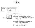
- a method is initialized in FIG the individual areas 1 to 4 of Figures 2a and 2b can be recognized and distinguished from one another.
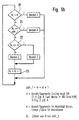
- the counter N1 is provided for this value Count up "1" to the value of number_1.
- N1 is greater than or equal to that number_1, the internal combustion engine 1 is corresponding to the Area 4 and thus operated in homogeneous operation.
- N1 is neither "0" nor greater than number_1
- a block 22 checked whether N1 is less than or equal to v1. If this is the case, the internal combustion engine 1 corresponding to area 2, i.e. with throttled Throttle valve 12, but otherwise with standard VH values operated. If this is not the case, however, the Internal combustion engine 1 corresponding to area 3, that is non-stationary homogeneous operation. In both cases the method is continued with a block 23.
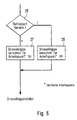
- a block 25 in FIG. 6 determines whether the Area 1 exists. This is done on the basis of the Method according to Figures 5a and 5b. Is area 1 before, the position of the Throttle valve 12 for a certain working point in Stratified charge operation, i.e. in the Compression stroke injection VH determined and set. If this is not the case, however, in a block 27 determine the position of the throttle valve 12 for the same Working point in homogeneous operation, i.e. in the Suction stroke injection SH determined and set.
- FIG. 7a the process is carried out in a block 29 of Figures 5a and 5b determines whether area 1 or Area 2 exists. If this is the case, then in one Block 30 determines the standard VH values and it becomes the Internal combustion engine 1 is influenced accordingly.
- these Standard VH values are those for the figures 2a and 2b already explained standard VH values for the Start of control ASB-VH, the injection duration ti-VH and the Ignition angle ZW-VH.
- the standard SH values are determined in a block 31. These standard SH values are the the standard SH value already explained in FIGS. 2a and 2b for the start of control ASB-SH. Furthermore, it is around the standard SH values for the injection duration ti-SH and the ignition angle ZW-SH.
- a subsequent block 32 it is checked whether the Area 4 is present. If this is the case, then the area lies 4 before. In this area 4 the operating parameters of the Internal combustion engine 1 according to the homogeneous operation The default values ti-SH and ZW-SH are set used immediately.
- area 4 is not present, then it is transient homogeneous operation of area 3 of Internal combustion engine 1 before, in a block 33 Transitional calculation carried out.
- a function P ti-SH-inst and a function ZW-Delta are determined in accordance with FIG. 7b.
- the course of both functions can be linear or also curved. Both functions start at the transition from area 2 to area 3 from an initial value that is greater than the value "1". The initial value is positive for the F ti-SH-inst function, while the initial value is negative for the ZW-Delta function.
- the function F ti-SH-inst ends with the transition from area 3 to area 4 with the value "1"
- the function ZW-Delta ends with the value "0".
- the function F ti-SH-inst and / or the function ZW-Delta can be predefined.
- the functions can be determined or can be determined by previous or simultaneous simulation and / or model calculations.
- the function F ti-SH-inst or the function ZW-Delta are linked multiplicatively or additively with the associated standard SH values.
- the standard SH value ti-SH results the course of the injection duration shown in Figure 2b ti in area 3.
- the standard SH value results ZW-SH the course of the shown in Figure 2b Ignition angle ZW in area 3.
- the increase in the injection duration ti resulting from the function F ti-SH-inst and shown in FIG. 2b would result in an increase in the torque generated and delivered by the internal combustion engine.
- This increase in fuel mass is necessary in order to achieve a defined, homogeneous, ignitable mixture.
- the retarded adjustment of the ignition ensures that an essentially constant torque is maintained when switching from stratified charge mode VH to homogeneous mode SH.
- Figures 3a and 3b as well as in Figures 4a and 4b the switch from homogeneous operation to Stratified charge operation in the form of two Time charts are shown in which different Operating variables of the internal combustion engine 1 are plotted.
- Figures 3a and 3b and 4a and 4b correspond in their Structure essentially Figures 2a and 2b, on the as far as is referred.
- Figures 3a and 3b and in Figures 4a and 4b are two alternatives of switching from that Homogeneous operation in stratified charge operation, i.e. from SH according to VH.
- the area 4 represents the homogeneous operation SH and area 1 represent stratified charge operation VH, while in the intermediate area 5 the switching he follows.
- the area 4 also represents the homogeneous operation SH and area 1 represents stratified charge operation VH, while in between the two areas 5 and 6 of the switchover serve.
- the switchover starts with End of area 4 and the switchover ends with Start of area 1.
- the Throttle valve 12 with the end of area 4 that is, with the End of homogeneous operation from the standard value DK-SH to Standard value DK-VH changed suddenly.
- the Start of control for the injection of fuel into the Combustion chamber 4 with the beginning of area 1 of that Standard value ASB-SH jumped to the standard value ASB-VH changed.
- the ignition angle ZW from the default value ZW-SH over time adjusted in order to then transition to area 1 to change abruptly to the standard value ZW-VH.
- the Injection duration ti increases based on the standard value ti-SH during the area 5 with time, then in Transition to area 1 jumped to the To decrease the default value ti-VH.
- the second alternative according to FIGS. 4a and 4b the start of control for the injection of fuel at Transition from area 5 to area 6 abruptly from the standard value ASB-SH to the standard value ASB-VH reduced.
- the ignition angle ZW and the injection duration ti are still at the default values during range 5 ZW-SH and ti-SH held.
- the ignition angle becomes from the standard value ZW-SH suddenly changed to the standard value ZW-VH.
- the Injection duration ti becomes the transition from area 5 to area 6 first jump to a value decreased, which is smaller than the standard value ti-SH, which but is even greater than the default ti-VH. Then it will be the injection duration from this value over time of area 6 reduced to the standard value ti-VH.
Description
- Figur 1
- zeigt ein schematisches Blockschaltbild eines Ausführungsbeispiels einer erfindungsgemäßen Brennkraftmaschine eines Kraftfahrzeugs,
- Figur 2a
- zeigt ein schematisches Zeitdiagramm der Einspritzungen und Zündungen der einzelnen Zylinder der Brennkraftmaschine der Figur 1 bei der Umschaltung von der ersten in die zweite Betriebsart,
- Figur 2b
- zeigt ein schematisches Zeitdiagramm von Signalen zur Steuerung und/oder Regelung der Brennkraftmaschine der Figur 1 bei der Umschaltung von der ersten in die zweite Betriebsart,
- Figur 3a
- zeigt ein schematisches Zeitdiagramm der Einspritzungen und Zündungen der einzelnen Zylinder der Brennkraftmaschine der Figur 1 bei einer ersten Alternative der Umschaltung von der zweiten in die erste Betriebsart,
- Figur 3b
- zeigt ein schematisches Zeitdiagramm von Signalen zur Steuerung und/oder Regelung der Brennkraftmaschine der Figur 1 bei einer ersten Alternative der Umschaltung von der zweiten in die erste Betriebsart,
- Figur 4a
- zeigt ein schematisches Zeitdiagramm der Einspritzungen und Zündungen der einzelnen Zylinder der Brennkraftmaschine der Figur 1 bei einer zweiten Alternative der Umschaltung von der zweiten in die erste Betriebsart,
- Figur 4b
- zeigt ein schematisches Zeitdiagramm von Signalen zur Steuerung und/oder Regelung der Brennkraftmaschine der Figur 1 bei einer zweiten Alternative der Umschaltung von der zweiten in die erste Betriebsart,
- Figur 5a
- zeigt ein schematisches Ablaufdiagramm der Initialisierung der Steuerung für die Umschaltung der Brennkraftmaschine der Figur 1 von der ersten in die zweite Betriebsart gemäß den Figuren 2a und 2b,
- Figur 5b
- zeigt ein schematisches Ablaufdiagramm der Steuerung der Umschaltung der Brennkraftmaschine der Figur 1 von der ersten in die zweite Betriebsart gemäß den Figuren 2a und 2b,
- Figur 6
- zeigt eine schematisches Ablaufdiagramm der Steuerung der Drosselklappe der Brennkraftmaschine der Figur 1 von der ersten in die zweite Betriebsart gemäß den Figuren 2a und 2b,
- Figur 7a
- zeigt ein schematisches Ablaufdiagramm der Steuerung und/oder Regelung von Betriebsgrößen der Brennkraftmaschine der Figur 1 von der ersten in die zweite Betriebsart gemäß den Figuren 2a und 2b, und
- Figur 7b
- zeigt zwei schematische Zeitdigramme von Betriebsgrößen der Figur 7a.
Claims (5)
- Verfahren zum Betreiben einer Brennkraftmaschine (1) insbesondere eines Kraftfahrzeugs, bei dem Kraftstoff entweder in einer ersten Betriebsart (VH) während einer Verdichtungsphase oder in einer zweiten Betriebsart (SH) während einer Ansaugphase direkt in einen Brennraum (4) eingespritzt wird, bei dem zwischen den beiden Betriebsarten (VH, SH) umgeschaltet wird, und bei dem die die eingespritzte Kraftstoffmasse beeinflussende Einspritzdauer (ti) in den beiden Betriebsarten (VH, SH) unterschiedlich gesteuert und/oder geregelt werden, dadurch gekennzeichnet, daß bei dem Umschalten von der ersten Betriebsart (VH) in die zweite Betriebsart (SH) die Einspritzdauer (ti) durch eine Funktion (Fti-SH-inst) beeinflußt wird, die von einem positiven Anfangswert, der größer ist als der Wert "1", auf einen Endwert "1" verläuft, wobei die Funktion (Fti-SH-inst) multiplikativ mit der an sich für die zweite Betriebsart (SH) vorgesehene Einspritzdauer (ti-SH) verknüpft wird.
- Verfahren nach Anspruch 1, dadurch gekennzeichnet, daß die Funktion (Fti-SH-inst) aus einer Simulations- bzw. Modellrechnung ermittelt wird.
- Verfahren nach einem der Ansprüche 1 oder 2, dadurch gekennzeichnet, daß die Funktion (Fti-SH-inst) in Abhängigkeit von einer oder mehreren Betriebsgrößen der Brennkraftmaschine (1) verändert wird.
- Verfahren nach einem der Ansprüche 1 bis 4, dadurch gekennzeichnet, daß die Funktion (Fti-SH-inst) in einem zeitlichen Bereich (Bereich 3) vorgegeben wird, in dem eine Erhöhung der an sich für die zweite Betriebsart (SH) vorgesehenen Einspritzdauer (ti-SH) erforderlich ist, um das abgegebene Moment der Brennkraftmaschine (1) konstant zu halten.
- Brennkraftmaschine (1) insbesondere für ein Kraftfahrzeug, mit einem Einspritzventil (8), mit dem Kraftstoff entweder in einer ersten Betriebsart (VH) während einer Verdichtungsphase oder in einer zweiten Betriebsart (SH) während einer Ansaugphase direkt in einen Brennraum (4) eingespritzt wird, und mit einem Steuergerät (16) zur Umschaltung zwischen den beiden Betriebsarten (VH, SH) und zur unterschiedlichen Steuerung und/oder Regelung der die eingespritzte Kraftstoffmasse beeinflussenden Einspritzdauer (ti) in den beiden Betriebsarten (VH, SH), dadurch gekennzeichnet, daß durch das Steuergerät (16) bei dem Umschalten von der ersten Betriebsart (VH) in die zweite Betriebsart (SH) die an sich für die zweite Betriebsart (SH) vorgesehene Einspritzdauer (ti-SH) durch eine Funktion (Fti-SH-inst) multiplikativ beeinflußt wird, die von einem positiven Anfangswert, der größer ist als der Wert "1", auf einen Endwert "1" verläuft.
Applications Claiming Priority (3)
| Application Number | Priority Date | Filing Date | Title |
|---|---|---|---|
| DE19828035A DE19828035A1 (de) | 1998-06-24 | 1998-06-24 | Verfahren zum Betreiben einer Brennkraftmaschine |
| DE19828035 | 1998-06-24 | ||
| PCT/DE1999/001725 WO1999067524A2 (de) | 1998-06-24 | 1999-06-12 | Verfahren zum betreiben einer brennkraftmaschine |
Publications (2)
| Publication Number | Publication Date |
|---|---|
| EP1099052A2 EP1099052A2 (de) | 2001-05-16 |
| EP1099052B1 true EP1099052B1 (de) | 2002-11-27 |
Family
ID=7871804
Family Applications (1)
| Application Number | Title | Priority Date | Filing Date |
|---|---|---|---|
| EP99938185A Expired - Lifetime EP1099052B1 (de) | 1998-06-24 | 1999-06-12 | Verfahren zum betreiben einer brennkraftmaschine |
Country Status (5)
| Country | Link |
|---|---|
| US (1) | US6394065B1 (de) |
| EP (1) | EP1099052B1 (de) |
| JP (1) | JP2002519560A (de) |
| DE (2) | DE19828035A1 (de) |
| WO (1) | WO1999067524A2 (de) |
Families Citing this family (5)
| Publication number | Priority date | Publication date | Assignee | Title |
|---|---|---|---|---|
| DE10115750B4 (de) | 2001-03-20 | 2017-05-24 | Robert Bosch Gmbh | Verfahren und Vorrichtung zur Steuerung und/oder Diagnose eines einen Massenstrom beeinflussenden Steuersystems |
| DE10239397B4 (de) * | 2002-08-28 | 2013-04-11 | Robert Bosch Gmbh | Verfahren zum Betreiben einer Brennkraftmaschine insbesondere eines Kraftfahrzeugs |
| DE102004031296B4 (de) * | 2004-06-29 | 2007-12-27 | Audi Ag | Verfahren zum Betreiben einer Brennkraftmaschine |
| DE102008057928B4 (de) | 2008-11-19 | 2023-03-02 | Bayerische Motoren Werke Aktiengesellschaft | Verfahren zur Steuerung einer direkteinspritzenden Otto-Brennkraftmaschine |
| FR3007075B1 (fr) * | 2013-06-12 | 2016-12-09 | Renault Sa | Procede de changement du motif d'injection de carburant d'un moteur a allumage commande d'un vehicule automobile, ensemble de combustion de carburant, moteur et vehicule automobile |
Family Cites Families (9)
| Publication number | Priority date | Publication date | Assignee | Title |
|---|---|---|---|---|
| EP0369480A3 (de) * | 1988-11-18 | 1991-01-02 | Toyota Jidosha Kabushiki Kaisha | Brennkraftmaschine |
| JP3404059B2 (ja) | 1992-10-08 | 2003-05-06 | 富士重工業株式会社 | 筒内直噴式エンジンの燃料噴射方法 |
| JP3201936B2 (ja) | 1995-09-29 | 2001-08-27 | 株式会社日立製作所 | 筒内噴射エンジンの制御装置 |
| DE19631986A1 (de) * | 1996-08-08 | 1998-02-12 | Bosch Gmbh Robert | Steuereinrichtung für eine direkteinspritzende Benzinbrennkraftmaschine |
| SE522177C2 (sv) * | 1996-08-27 | 2004-01-20 | Mitsubishi Motors Corp | Styranordning för en förbränningsmotor med cylinderinsprutning och gnisttändning |
| JP3680492B2 (ja) * | 1997-06-03 | 2005-08-10 | 日産自動車株式会社 | 内燃機関の制御装置 |
| EP0889218B1 (de) * | 1997-07-01 | 2007-08-08 | Nissan Motor Company, Limited | Brennstoffeinspritzsteuerungssystem für Innenverbrennungsmotoren |
| JP3536606B2 (ja) * | 1997-08-21 | 2004-06-14 | 日産自動車株式会社 | 直噴火花点火式内燃機関の燃料噴射制御装置 |
| US6470869B1 (en) * | 1999-10-18 | 2002-10-29 | Ford Global Technologies, Inc. | Direct injection variable valve timing engine control system and method |
-
1998
- 1998-06-24 DE DE19828035A patent/DE19828035A1/de not_active Ceased
-
1999
- 1999-06-12 WO PCT/DE1999/001725 patent/WO1999067524A2/de active IP Right Grant
- 1999-06-12 DE DE59903561T patent/DE59903561D1/de not_active Expired - Lifetime
- 1999-06-12 US US09/720,336 patent/US6394065B1/en not_active Expired - Fee Related
- 1999-06-12 JP JP2000556150A patent/JP2002519560A/ja active Pending
- 1999-06-12 EP EP99938185A patent/EP1099052B1/de not_active Expired - Lifetime
Also Published As
| Publication number | Publication date |
|---|---|
| WO1999067524A3 (de) | 2000-03-09 |
| EP1099052A2 (de) | 2001-05-16 |
| WO1999067524A2 (de) | 1999-12-29 |
| JP2002519560A (ja) | 2002-07-02 |
| DE19828035A1 (de) | 1999-12-30 |
| US6394065B1 (en) | 2002-05-28 |
| DE59903561D1 (de) | 2003-01-09 |
Similar Documents
| Publication | Publication Date | Title |
|---|---|---|
| EP0923666B1 (de) | System zum betreiben einer brennkraftmaschine insbesondere eines kraftfahrzeugs | |
| DE19743492A1 (de) | Verfahren zum Starten einer Brennkraftmaschine insbesondere eines Kraftfahrzeugs | |
| DE19936201A1 (de) | Verfahren zum Betreiben einer Brennkraftmaschine | |
| EP0995025B1 (de) | Verfahren zum betreiben einer brennkraftmaschine insbesondere eines kraftfahrzeugs | |
| DE10239397B4 (de) | Verfahren zum Betreiben einer Brennkraftmaschine insbesondere eines Kraftfahrzeugs | |
| EP1090221B1 (de) | Verfahren zum betreiben einer brennkraftmaschine insbesondere eines kraftfahrzeugs | |
| EP1015749B1 (de) | Verfahren zum betreiben einer brennkraftmaschine | |
| EP1066458B1 (de) | Verfahren zum betreiben einer brennkraftmaschine | |
| EP0995026B1 (de) | Verfahren zum betreiben einer brennkraftmaschine | |
| DE4334864C2 (de) | Verfahren und Vorrichtung zur Steuerung einer Brennkraftmaschine | |
| EP1003960B1 (de) | Verfahren zum betreiben einer brennkraftmaschine | |
| EP1099052B1 (de) | Verfahren zum betreiben einer brennkraftmaschine | |
| EP1099051B1 (de) | Verfahren zum betreiben einer brennkraftmaschine | |
| DE19958465C2 (de) | Verfahren zum Betreiben einer Brennkraftmaschine | |
| DE19827105C2 (de) | Verfahren zum Betreiben einer Brennkraftmaschine insbesondere eines Kraftfahrzeugs | |
| EP0985089B1 (de) | Verfahren zum betreiben einer brennkraftmaschine insbesondere eines kraftfahrzeugs | |
| DE10156409A1 (de) | Verfahren zur Verbesserung der Laufruhe und entsprechender Motor | |
| DE19941528A1 (de) | Verfahren zum Betreiben einer Brennkraftmaschine | |
| EP1057992A2 (de) | Verfahren zum Betreiben einer Brennkraftmaschine | |
| DE19908726A1 (de) | Verfahren zum Betreiben einer Brennkraftmaschine | |
| DE19954207C2 (de) | Verfahren zum Betreiben einer Brennkraftmaschine | |
| WO2003031792A1 (de) | Verfahren zum betreiben einer brennkraftmaschine insbesondere eines kraftfahrzeugs | |
| EP1046803A2 (de) | Verfahren zum Betreiben einer Brennkraftmaschine | |
| DE19840706A1 (de) | Verfahren zum Betreiben einer Brennkraftmaschine insbesondere eines Kraftfahrzeugs |
Legal Events
| Date | Code | Title | Description |
|---|---|---|---|
| PUAI | Public reference made under article 153(3) epc to a published international application that has entered the european phase |
Free format text: ORIGINAL CODE: 0009012 |
|
| 17P | Request for examination filed |
Effective date: 20010124 |
|
| AK | Designated contracting states |
Kind code of ref document: A2 Designated state(s): DE FR IT |
|
| 17Q | First examination report despatched |
Effective date: 20010525 |
|
| GRAG | Despatch of communication of intention to grant |
Free format text: ORIGINAL CODE: EPIDOS AGRA |
|
| GRAG | Despatch of communication of intention to grant |
Free format text: ORIGINAL CODE: EPIDOS AGRA |
|
| GRAH | Despatch of communication of intention to grant a patent |
Free format text: ORIGINAL CODE: EPIDOS IGRA |
|
| GRAH | Despatch of communication of intention to grant a patent |
Free format text: ORIGINAL CODE: EPIDOS IGRA |
|
| GRAA | (expected) grant |
Free format text: ORIGINAL CODE: 0009210 |
|
| AK | Designated contracting states |
Kind code of ref document: B1 Designated state(s): DE FR IT |
|
| REF | Corresponds to: |
Ref document number: 59903561 Country of ref document: DE Date of ref document: 20030109 |
|
| ET | Fr: translation filed | ||
| PLBE | No opposition filed within time limit |
Free format text: ORIGINAL CODE: 0009261 |
|
| STAA | Information on the status of an ep patent application or granted ep patent |
Free format text: STATUS: NO OPPOSITION FILED WITHIN TIME LIMIT |
|
| 26N | No opposition filed |
Effective date: 20030828 |
|
| PGFP | Annual fee paid to national office [announced via postgrant information from national office to epo] |
Ref country code: FR Payment date: 20050621 Year of fee payment: 7 |
|
| PGFP | Annual fee paid to national office [announced via postgrant information from national office to epo] |
Ref country code: IT Payment date: 20060630 Year of fee payment: 8 |
|
| REG | Reference to a national code |
Ref country code: FR Ref legal event code: ST Effective date: 20070228 |
|
| PG25 | Lapsed in a contracting state [announced via postgrant information from national office to epo] |
Ref country code: FR Free format text: LAPSE BECAUSE OF NON-PAYMENT OF DUE FEES Effective date: 20060630 |
|
| PG25 | Lapsed in a contracting state [announced via postgrant information from national office to epo] |
Ref country code: IT Free format text: LAPSE BECAUSE OF NON-PAYMENT OF DUE FEES Effective date: 20070612 |
|
| PGFP | Annual fee paid to national office [announced via postgrant information from national office to epo] |
Ref country code: DE Payment date: 20130828 Year of fee payment: 15 |
|
| REG | Reference to a national code |
Ref country code: DE Ref legal event code: R119 Ref document number: 59903561 Country of ref document: DE |
|
| REG | Reference to a national code |
Ref country code: DE Ref legal event code: R119 Ref document number: 59903561 Country of ref document: DE Effective date: 20150101 |
|
| PG25 | Lapsed in a contracting state [announced via postgrant information from national office to epo] |
Ref country code: DE Free format text: LAPSE BECAUSE OF NON-PAYMENT OF DUE FEES Effective date: 20150101 |